POWER PROVE AC6 Operating instructions

Operating and Maintenance Manual
AC6 load bank
Single; 230V AC 1-phase
Dual; 110V and 230V AC 1-phase
Reference No.
161878
Revision
B
Revision ref. (ECN)
13801
Date
23-DEC-2020
Author
AK
Power Prove
www.powerprove.com
Leicester. LE5 5LZ. United Kingdom
sales@powerprove.com
a division of Cressall Resistors Ltd.
+44(0) 116 249 1722

Document Operating and Maintenance manual, AC6 load bank
Reference No. 161878
Revision B
Date 23-DEC-2020
Author AK
Power Prove www.powerprove.com
Leicester. LE5 5LZ. United Kingdom sales@powerprove.com
a division of Cressall Resistors Ltd. +44(0) 116 249 1722 Page 1 of 4
Operating and maintenance manual
AC6, 6kW AC 1-phase load bank
Figure 1 - Product photo with cover removed. AC6 "Dual" voltage version shown
! Warnings
Prior to use
Prior to us ensure that operators are familiar with this document.
First use
When initially energised this product emits a small amount of smoke for a short period. On subsequent operations this
effect will disappear.
During use
When testing for a continuous period of more than 5 minutes the exit grill and adjacent covers will become hazardously
hot to touch and remain hot for approximately 20minutes after testing is completed. The exiting air will also be hot
(>100°C). Exercise care when touching casework (especially exit grill) even after power supply is disconnected.

Document Operating and Maintenance manual, AC6 load bank
Reference No. 161878
Revision B
Date 23-DEC-2020
Author AK
Power Prove www.powerprove.com
Leicester. LE5 5LZ. United Kingdom sales@powerprove.com
a division of Cressall Resistors Ltd. +44(0) 116 249 1722 Page 2 of 4
Safety
Usage environment
This product is designed for indoor use, i.e. in dry conditions. Do not use outside in wet weather conditions.
Remove any combustible materials from the test area.
Position ideally on flat horizontal surface.
Ventilation
Do not cover or obstruct the ventilation inlet and outlet grills. Ensure free movement of air at fan inlet. Minimum
recommended clearance from the air outlet of 1000mm.
Instructions for use
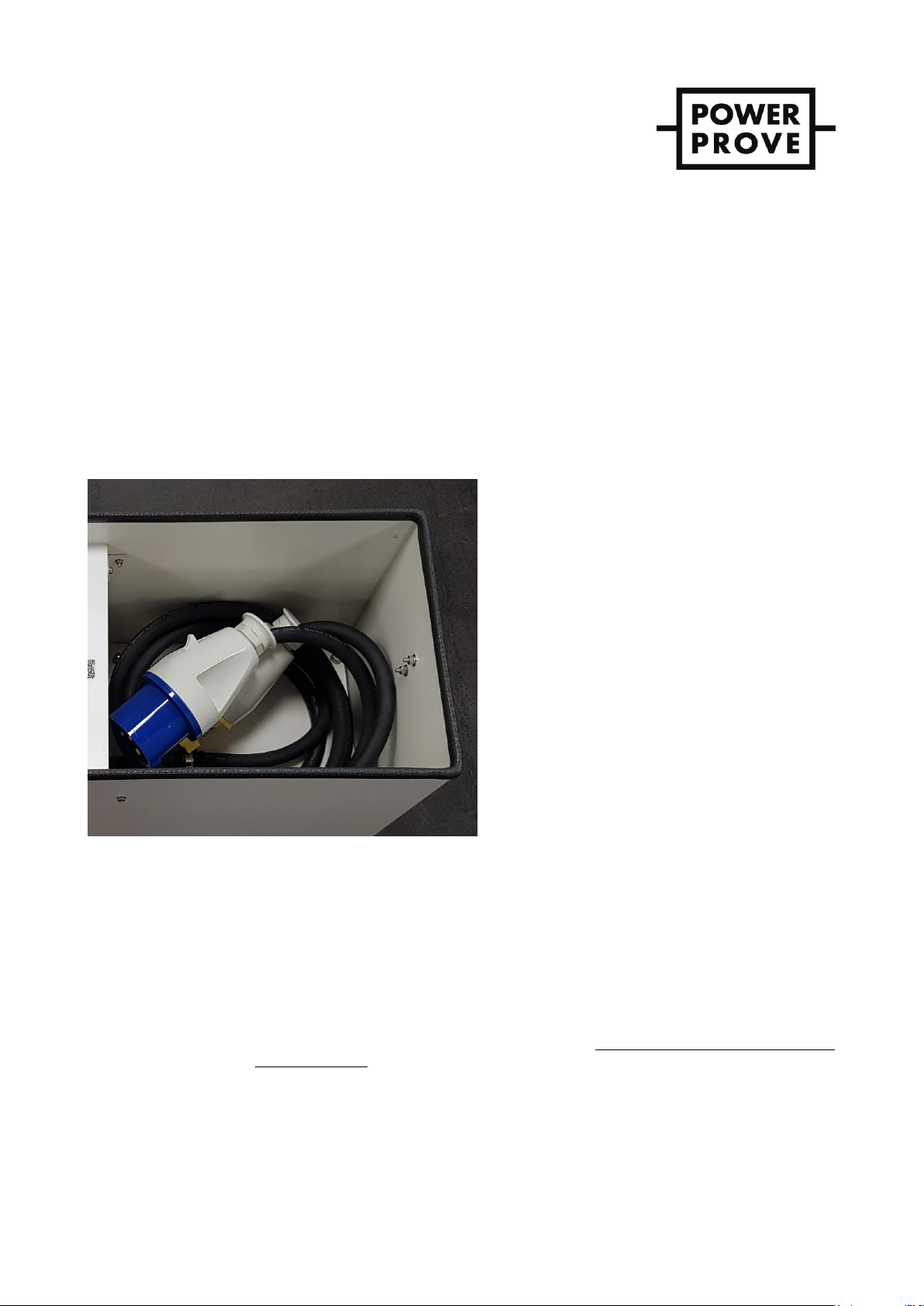
Figure 2 –integrated leads with IEC 60309-2 inline socket(s) with 2P+PE pins
Connect Supply to approved IEC60309-2 Plug / Socket Connectors (2P+E pattern), 230V 50-60Hz 32A (blue).
Dual voltage version has an additional lead and socket for 110V 50-60Hz 32A, yellow.
With power selector switch and load switches in their “off” positions, start the supply (generator) for test.
Switch test supply to desired voltage suitable for the operation of the load bank.
Switch on the load bank using the main power switch.
On the dual voltage version this is a selector switch; select either 230V or 110V.
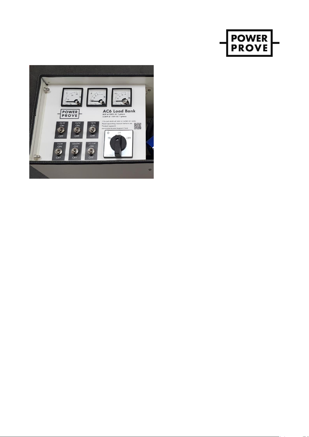
Verify the fan is running and the voltage & frequency is indicated on the corresponding meters –see Figure 3.
Select the desired loads in turn using the toggle switches, in steps of 2kW, 1kW, 0.33kW, or 0.66kW.
Maximum load is 6kW.
On the dual voltage version, when operating at 110V, do not operate continuously at loads in
excess of 3.68kW (32A).
When testing is complete switch of the load sections using the toggle switches.
Run fan for 5 minutes after completing test to cool the unit.
Once cooling time is complete and with all load toggle switches off, switch off the complete unit using the main
power selector switch.

Document Operating and Maintenance manual, AC6 load bank
Reference No. 161878
Revision B
Date 23-DEC-2020
Author AK
Power Prove www.powerprove.com
Leicester. LE5 5LZ. United Kingdom sales@powerprove.com
a division of Cressall Resistors Ltd. +44(0) 116 249 1722 Page 3 of 4
Figure 3 - AC6 control panel (AC6 dual shown)
Maintenance
Before performing any maintenance on the equipment, first isolate the power source, and lock-off appropriately.
Check tightness of connections. This should be done at regular intervals.
Inspect for dirt or accumulation of contaminants on insulators or obstructions to ventilation holes; clean as appropriate.
Ensure warning labels are fitted and visible, there should be two:
1. Hot Surface warning above the air outlet.
2. Electrical flash on the removable access plate.
Electrical Safety Tests
Use and insulation resistance tester at 250V DC device with all switches in ‘on’ position to check the insulation resistance
between the live and neutral pins and PE pin and metals switches. The minimum acceptable value is 100MΩ.

Document Operating and Maintenance manual, AC6 load bank
Reference No. 161878
Revision B
Date 23-DEC-2020
Author AK
Power Prove www.powerprove.com
Leicester. LE5 5LZ. United Kingdom sales@powerprove.com
a division of Cressall Resistors Ltd. +44(0) 116 249 1722 Page 4 of 4
Troubleshooting
Load sections and fan
Miniature circuit breaker(s) (MCB) are provided for both short circuit or over current protection. the fan and/or load
sections not function correctly the MCB(s) may have tripped.
With the load bank isolated from the power source, verify that all connections are correctly fitted & properly tightened.
Verify that the load section resistance values correspond to values indicated on the schematic diagram (within +/-10%).
Check the position of the MCB, reset and re-run the load, verify that correct voltage is being applied during testing.
If the MCB(s) continue to trip, then please contact us for an equipment inspection and re-test.
Instrumentation
Should instrumentation not operate, check the 1A instrument fuse and replace if necessary.
If the instrument continues to not operate with a functioning fuse, please contact us for replacement meters or for our
equipment inspection service.
Spares
Enquire with reference to resistor product code and serial number, as shown on rating plate.
We offer a full equipment inspection, repair (when necessary) and re-test service for any of our load banks at our
headquarters in Leicester, UK.
Table of contents
Popular Power Supply manuals by other brands

Whelen Engineering Company
Whelen Engineering Company WPPS6922 installation guide

T+A
T+A PS 3000 HV user manual

Asus
Asus REPUBLIC OF GAMERS ROG Stix PSU 650W quick start guide

Cooper Crouse-Hinds
Cooper Crouse-Hinds GHG 664 Series operating instructions

Elenco Electronics
Elenco Electronics XP-625 instruction manual

Crestron
Crestron CSA-PWS10S-HUB installation guide