Power Tec 71536 User manual
Owner’s Manual
Model No. 71536
24" Router Table Fence
You will need this manual for safety instructions, operating procedures, and warranty.
Put it and the original sales invoice in a safe, dry place for future reference.
Visit us on the web at powertecproducts.com
QUESTION...
1•847•780•6120
20-0616

TABLE OF CONTENTS
SAFETY RULES 1
ASSEMBLY 3
MAINTENANCE 6
General Maintenance
WARRANTY 7
SECTION PAGE
Unpacking
Assembly
Adjusting theFence Faces
Jointing

SAFETY RULES 1
1
SAFETY RULES
WARNING
For your own safety, read all of the rules and precautions before
operating tool.
WARNING
Always follow proper operating procedures as defined in this
manual even if you are familiar with use of this router table
fence or any tool used with this router table fence. Remember
that being careless for even a fraction of a second can result in
severe personal injury.
Before using another tool with this product, always read,
understand and follow the instructions and safety warnings in
the owner’s manual for that tool. If you do not have the owner’s
manual, obtain one from the tool’s manufacturer before using it
with this product.
You must be familiar with the use of any tool or accessory
used with this router table fence. The supplier cannot be held
responsible for any accident, injury or damage incurred while
using this router table fence with any tool.
It is the responsibility of the purchaser of this product to ensure
that any person using this product reads and complies with all
instructions and safety precautions outlined in this manual prior
to use.
WARNING
Some dust created by operation of power tool contains
chemicals known to the State of California to cause cancer, birth
defects or other reproductive harm. To reduce your exposure
to these chemicals, work in a well ventilated area and work
with approved safety equipment. Always wear OSHA/NIOSH
approved, properly fitting face mask or respirator when using
such tools.
CAUTION
Do not modify or use this router table fence for any application
other than that for which it was designed.
FOLLOW ALL STANDARD SHOP SAFETY
PRECAUTIONS, INCLUDING:
• Keep children and visitors at a safe distance from work area.
• Keep work area clean. Cluttered work areas invite accidents.
Work area should be properly lit.
• Do not use power tools in dangerous environments. Do not
use power tools in damp or wet locations. Do not expose
power tools to rain.
• Wear proper apparel. Do not wear loose clothing, gloves,
neckties, rings, bracelets or other jewelry which may get
caught in moving parts of the tool.
• Wear protective hair covering to contain long hair.
• Wear safety shoes with non-slip soles.
• Wear safety glasses complying with United States ANSI
Z87.1. Everyday glasses have only impact resistant lenses.
They are NOT safety glasses.
• Wear face mask or dust mask if operation is dusty.
• Be alert and think clearly. Never operate power tools when
tired, intoxicated or when taking medications that cause
drowsiness.
• A guard or any other part that is damaged should be properly
repaired or replaced. Do not perform makeshift repairs.
• Use the right tool for your job. Do not force your tool to do a
job for which it was not designed.
• Use safety equipment such as featherboards, push sticks and
push blocks, etc., when appropriate.
• Maintain proper footing at all times and do not overreach.
• Do not use the router table as a step or seat.
WARNING
• To avoid serious injury, turn off and unplug the router before
attaching the router base, changing accessories or adjusting
the cutter height/fence position.
• Assemble the featherboard(s) at least 1" (2.5 cm) from the
saw blade to prevent kickback.
• Do not use the featherboard as a push block.
CAUTION
Think safety! Safety is a combination of operator common sense
and alertness at all times when tool is being used.
WARNING
Do not use the router table fence until it is completely assembled
and you have read and understood this entire operating manual
and the operating manual of the tool being used with this router
table fence.
SAVE ALL WARNINGS AND INSTRUCTIONS
FOR FUTURE REFERENCE

SPECIFIC SAFETY WARNINGS
2
DANGER
• To avoid serious injury, keep hands and fingers away from the
spinning router bit. Be aware of the bit at all times.
WARNING
AVOID THIS SITUATION!
Fence
Workpiece
Direction
of Feed
Bit Rotation
-NEVER FEED YOUR WORKPIECE BETWEEN THE
BIT AND THE FENCE. Because of the direction of
the bit’s rotation, the bit could “grab” the workpiece
and propel it away from the table at a high velocity,
potentially resulting in property damage and serious
injury to anyone in its path.
-When the bit grabs the workpiece, your hands could
be drawn into the bit, resulting in serious injury
• Turn off and unplug your router before installing or adjusting
the bit or adjusting the router table fence and accessories.
• BEFORE beginning any routing operation, ALWAYS make
sure ALL knobs on the router table fence and accessories are
tightened and the fence will not shift during use.
• Always feed the workpiece against the rotation of the bit.
A table-mounted router spins the bit counterclockwise, so
feed the workpiece from right to left as you face the table.
This provides better control because the rotation of the bit is
backward and toward the fence instead of forward and away
from it.
• NEVER attempt to machine a workpiece at the router table
without using the router table fence or a starter pin with a
bearing-guided bit. Failure to use these guides diminishes
your ability to control the workpiece and greatly increases
the chance of damage to the workpiece and/or serious
personal injury.
• BEFORE plugging in and turning on the router, always make
sure the MDF adjustable fence faces are fully secured and
the bit can rotate freely without touching the fence faces. An
exception to this is if the infeed fence face is set to provide
zero-clearance support for the workpiece, as described in the
Adjusting the Fence Faces.
CAUTION
• Set the bit guard directly over the router bit, at least 1/2" above
the top of the bit or the top of the workpiece (whichever is
highest), make sure the bit doesn’t cut into the bit guard.
• When adjusting the position of the router table fence, make
sure no part of the aluminum fence will contact the router bit.
2
SAFETY RULES
3
ASSEMBLY
ASSEMBLY 3
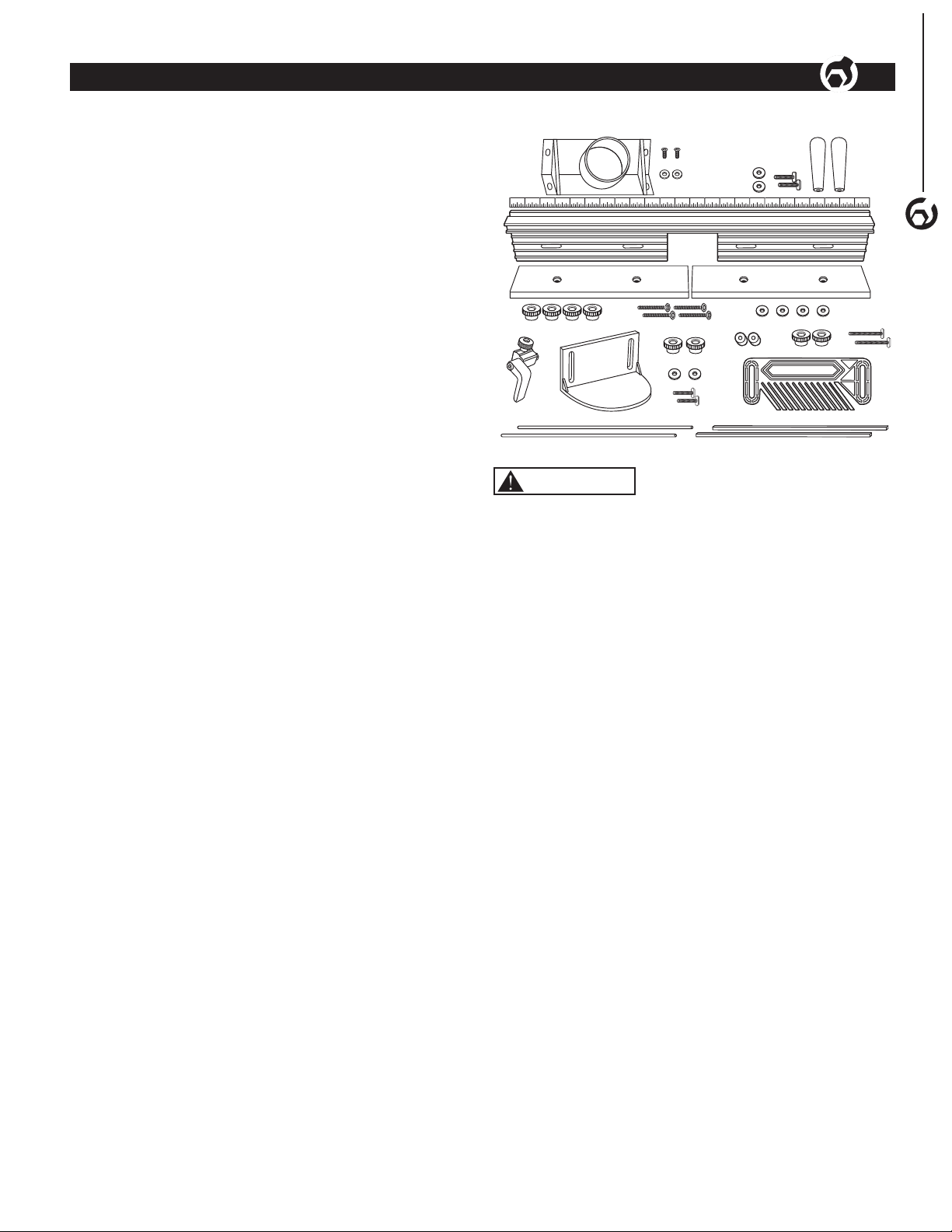
UNPACKING
Refer to Figure 1
Check for shipping damage. Check immediately whether all
parts and accessories are included.
ITEM DESCRIPTION QTY
A Fence 1
BFence lock knobs 2
CWashers 5/16" 2
DT-Bolt 5/16"-18 x 1" 2
EMDF adjustable fence faces 2
FFlat head screws 1/4"-20 x 1-1/2" 4
GWashers 1/4" 4
HLocking knobs 4
IBit guard 1
JBit guard knobs 1/4" 2
KT-Bolts 1/4"-20 x 1" 2
LWashers 1/4" 2
MRouter dust port 1
NPan head screws M4 x 10 mm 2
OWashers 1/4" 2
PFeatherboard 1
QT-Bolts 5/16"-18 x 1-1/2" 2
RSpacers 2
SLocking knobs 5/16" 2
TTape measure with adhesive backing
(right to left)
1
U3" Flip stop 1
V1/4" Square Rods 2
W4 mm Round Rods 2
Figure 1
2324 22 21 1520 1319 111218 91017 7
8
16 56 314 14 2
U
H
K
M
A
B
NC
O
GF
T
L
J
Q
R
P
E
I
S
D
E
W V
WARNING
Do not use the router table fence until it is completely assembled
and you have read and understood this entire operating manual
and the operating manual of the tool being used with this router
table fence.
4
ASSEMBLY
ASSEMBLY
Refer to Figure 2–4
• Remove the adhesive backing from the right to left tape
measure and press into place. Start on the right end and
carefully place the tape along the front edge of the fence. Use
scissors to cut the excess tape from the left end.
• Attach the dust port to the back of the fence using the pan
head screws and 1/4” washers.
• From the front of the MDF adjustable fence faces, insert the
1/4"-20 x 1-1/2” screws through the MDF adjustable fence face
and fence, place a 1/4” washer over each screw and secure
in place with the round locking knobs. The MDF adjustable
fence faces can be adjusted left or right, after adjustment
has been made for the operation to be performed, tighten all
knobs securely.
• From the bottom of the fence insert the two 5/16"-18 x 1”
T-Bolts through the fence slot. Place a 5/16” washer and fence
locking knob on each T-Bolt. Place the fence onto the router
table and align the T-Bolts in the fence with the slots in the
router table. Tighten the knobs after adjusting the fence to the
operation being preformed.
• From the back of the bit guard insert the two 1/4"-20 x 1”
T-Bolts, place 1/4" washers and round lock knobs on each
T-Bolt. Place the T-Bolts into the T-Slot on the face of the
fence and slide the bit guard onto the fence. NOTE: To
adjust the bit guard, loosen the knobs, slide the bit guard up
and down to desired application and tighten knobs. When
changing bits, slide the bit guard left or right of the opening.
WARNING
To prevent kickback make sure the featherboard is at least 1”
(2.5 cm) from the saw blade.
• Place a spacer on each 5/16"-18 x 1-1/2" long T-Bolt and
insert through the slot in the featherboard, thread a round
locking knob on each T-Bolt and slide the T-Bolts into the
T-slot in the front of the fence. Position the featherboard(s)
and tighten locking knobs.
• Slide the T-Bolt on the flip stop into the T-Slot in top of the
fence, tighten the knob. The arm on the flip stop functions
as an easily adjustable stop and can be flipped up when not
needed. NOTE: The flip stop is multi-functional, please see flip
stop instructions for details. To prevent chip build up, the stop
does not extend the full width of the fence. However when
using a stop with material 3/8" thick or less, a longer stop
will need to be fabricated and can be mounted in the T-slot
located in the front of the fence.
IMPORTANT: Every routing operation is different, adjust the
various parts of the router fence and accessories as needed and
then tighten all knobs securely.
ADJUSTING THE FENCE FACES
Refer to Figure 5
The two MDF adjustable fence faces are designed to slide about
2" along the fence. This allows the opening for the router bit to be
adjusted from 0” up to 4".
Generally, the infeed and outfeed adjustable fence faces should
be adjusted as close to the bit as possible without contacting
the cutter. This will help prevent the ends of the workpiece from
drifting too far into the cutter at the beginning and end of the cut to
provide quality and safe cut.
Sometimes the “zero-clearance” support is needed to deliver an
even cleaner cut. In this case the router bit profile cuts into the
front edge of the infeed adjustable fence face so there is virtually
no gap between the cutter and the fence face. It delivers a cleaner
cut because the workpiece fibers are fully supported throughout
the cut.
If a zero clearance setting is necessary, follow these steps:
1. Set the bit height and fence position. Set both of the MDF
adjustable fence faces close to the bit without touching it,
the fence faces MUST NOT contact the bit at this time.
CAUTION
Set the bit guard directly over the router bit, at least 1/2” above
the top of the bit or the top of the workpiece (whichever is
highest), make sure the bit doesn’t cut into the bit guard.
2. Install, adjust and secure the bit guard.
3. On the back of the fence, slightly loosen the locking knobs
on the infeed MDF adjustable fence face. Start the router
and slowly slide the infeed MDF adjustable fence face into
the spinning router bit, stopping when the edge reaches
the bit’s guide bearing or midpoint (for bits that don’t have a
guide bearing).
4. Tighten the locking knobs on the back of the MDF
adjustable fence face to secure it in position.
5
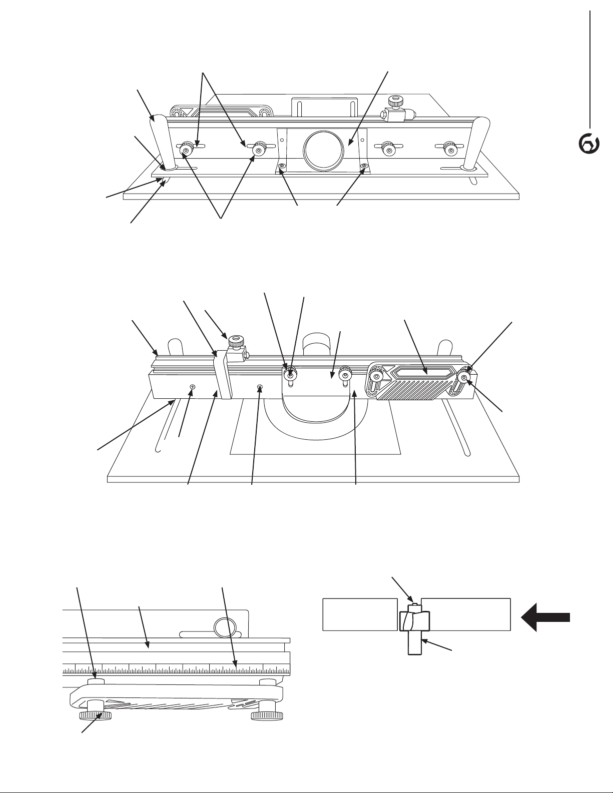
ASSEMBLY
BACK
Fench
Locking
Knob
5/16"
Washer
Slot in Router Table
Dust Port
T-Bolt
Slot in
Fence
Round Locking Knobs
with 1/4" Washers
Washer and Pan
Head Screw
Figure 2
FRONT
Bit Guard
Featherboard Round Locking Knob
Round Lock
Knobs with
Washers
MDF Adjustable Infeed Fence Face
Flip
Stop
Knob
T-Slot in Top
of Fence
1/4"-20 x 1"
T-Bolts
MDF Adjustable
Outfeed Fence Face
1/4-20
x 1-1/2"
Screws
1/4"-20 x 1-1/2" Screws
Flip
Stop
T-Slot in
Face of
Fence
Figure 3
2 1345678
87654321
T-Slot on Top of Fence
Right to Left Tape Measurer
NOTE: Use the tape measure
to position stops for routing
stopped cut.
Round
Locking
Knob
Spacer
Figure 4
5/16"-18 x 1-1/2"
T-Bolts
OUTFEED Adjustable
Fence Face
INFEED Adjustable
Fence Face
Router Bit
Router Bit Bushing Guide
Figure 5
GENERAL MAINTENANCE
WARNING
When servicing, use only identical replacement parts. Use of
any other parts may create a hazard or cause product damage.
To ensure safety and reliability, all repairs should be performed
by a qualified service technician.
MAINTENANCE
6
MAINTENANCE
6
WARNING
Keep the router table fence dry, clean, and free from oil and
grease. Always use a clean cloth when cleaning. Never use
brake fluids, gasoline, petroleum based products or any
strong solvent to clean the router table fence. Chemicals can
damage, weaken or destroy plastic which may result in serious
personal injury.
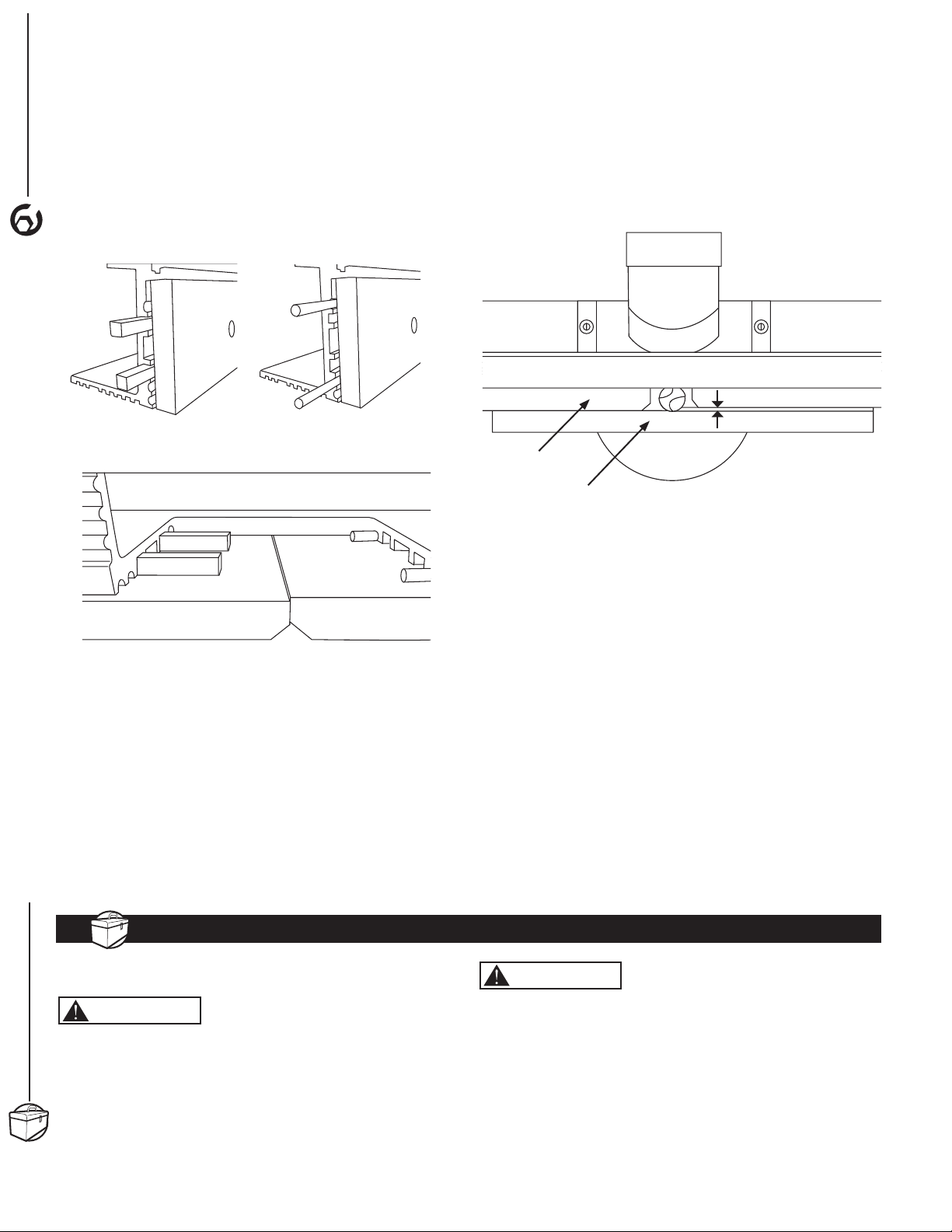
JOINTING
Refer to Figure 6–9
The independently adjustable fence faces allow the router table
to be used as a vertical jointer by offsetting the outfeed fence
face 3/128", 1/16", 5/64" from the infeed fence face.
Two sets of grooves are located in the fence behind the fence
faces, slide the jointing rods into these grooves to offset
the outfeed fence face 3/128", 1/16", 5/64" from the infeed
fence face.
Figure 7
Square Jointing Rods Shown in
the Square Grooves
Round Jointing Rods Shown in
the Round Grooves
Square Jointing Rods Shown in the Square Grooves on the
Outfeed Fence and the Round Jointing Rods in the Round Grooves
on the Infeed Fence for the 1/64" Offset
Figure 6
Figure 8
NOTE: It is best to make light passes when jointing, the
3/128" and 1/16" offset will be used more frequently than the
5/64" offset.
1. Loosen the round locking knobs securing the outfeed fence
face. Slide the jointing rods into the desired groove on
the fence.
a. For a 5/64" offset slide the square jointing rods into the
square grooves on the outfeed fence. Figure 6.
b. For a 1/16" offset, slide the round jointing rods into the
round grooves on the outfeed fence. Figure 7.
c. For a 3/128" offset, slide the round jointing rods into the
round grooves on the infeed fence and slide the square
rods into the square grooves on the outfeed fence.
Figure 8.
2. With the rods in place, tighten the outfeed fence face
locking knobs.
Jointing Offset
Outfeed Fence
Face
Workpiece
Figure 9
3. Install a straight bit in the router. Place a straight edge
against the outfeed fence face and position the fence so the
bit just grazes the straight edge.
NOTE: Any straight bit can be used for jointing. A flush-trim bit is
the easiest to set up because the bit guide bearing is the same
diameter as the cutter and it can be aligned to the outfeed fence
face with the bearing. An up-cut spiral bit produces an almost
chatter-free surface, but it is more difficult to align with the
fence face.
Always use a scrap piece of wood to test the setup.
• If the scrap is fed past the bit and it runs into the leading end
of the outfeed fence face, the fence is too far forward and
not enough material is being removed. Move the fence back
a little.
• If there is snipe at the trailing edge of the scrap, the fence is
too far back and too much material is being removed. Move
the fence forward.
6
ASSEMBLY

WARRANTY 7
WARRANTY
7
Thank you for investing in a POWERTEC power tool. This product has been designed and manufactured to meet high
quality standards and is guaranteed for domestic use against defects in workmanship or material for a period of 12
months from the date of purchase. This guarantee does not affect your statutory rights.
SOUTHERN TECHNOLOGIES LLC. BENCH TOP AND STATIONARY POWER TOOL
LIMITED 1 YEAR WARRANTY AND 30-DAY SATISFACTION GUARANTEE POLICY
POWERTEC products are designed and manufactured by Southern Technologies LLC. All warranty communications
should be directed to Southern Technologies LLC by calling 847-780-6120, 9 AM to 5 PM, Monday through Friday,
US Central Time.
30- DAY SATISFACTION GUARANTEE POLICY
During the rst 30 days after the date of purchase, if you are dissatised with the performance of this POWERTEC tool
for any reason, you may return the tool to the retailer from which it was purchased for a full refund or exchange. You
must present proof of purchase and return all original equipment packaged with the original product. The replacement
tool will be covered by the limited warranty for the balance of the one year warranty period.
LIMITED ONE YEAR WARRANTY
This warranty covers all defects in workmanship or materials in this POWERTEC tool for a one year period from the
date of purchase. This warranty is specic to this tool. Southern Technologies, LLC reserves the right to repair or
replace the defective tool, at its discretion.
HOW TO OBTAIN SERVICE
To obtain service for this POWERTEC tool you must return it, freight prepaid, to POWERTEC. You may call
847-780-6120 for more information. When requesting warranty service, you must present the proof of purchase
documentation, which includes a date of purchase. POWERTEC will either repair or replace any defective part, at
our option at no charge to you. The repaired or replacement unit will be covered by the same limited warranty for the
balance of one year warranty period.
WHAT IS NOT COVERED
This warranty applies to the original purchaser at retailer and may not be transferred.
This warranty does not cover consumable items such as saw blades, knives, belts, discs, cooling blocks and sleeves.
This warranty does not cover required service and part replacement resulting from normal wear and tear, including
accessory wear.
This warranty does not cover any malfunction, failure or defect resulting from:
1) misuse, abuse, neglect and mishandling not in accordance with the owner’s manual.
2) damage due to accidents, natural disasters, power outage, or power overload.
3) commercial or rental use.
4) alteration, modication or repair performed by persons not recommended by POWERTEC.
DISCLAIMER
To the extent permitted by applicable law, all implied warranties, including warranties of MERCHANTABILITY or
FITNESS FOR A PARTICULAR PURPOSE, are disclaimed. Any implied warranties, that cannot be disclaimed under
state law are limited to one year from the date of purchase. Southern Technologies LLC. is not responsible for direct,
indirect, incidental or consequential damages. Some states do not allow limitations on how long an implied warranty
lasts and/or do not allow the exclusion or limitation of incidental or consequential damages, so the above limitations
may not apply to you. This warranty gives you specic legal rights, and you may also have other rights which vary from
state to state. Southern Technologies LLC., makes no warranties, representations, or promises as to the quality or
performance of its power tools other than those specically stated in this warranty.

NOTE

NOTE

Southern Technologies, LLC
Waukegan, IL 60087
Table of contents
Other Power Tec Power Tools Accessories manuals


Popular Power Tools Accessories manuals by other brands


Bosch
Bosch GTA 3800 Professional Operating/safety instructions

Hilti
Hilti DC-EX 125/5inch M operating instructions

Bubble Magic
Bubble Magic Pollen Tumbler Replacement manual

Woodhaven
Woodhaven Micro Adjuster 3265 Assembly instructions

Toro
Toro 03857 Operator's manual

Milescraft
Milescraft ToolStand 1097 manual