4
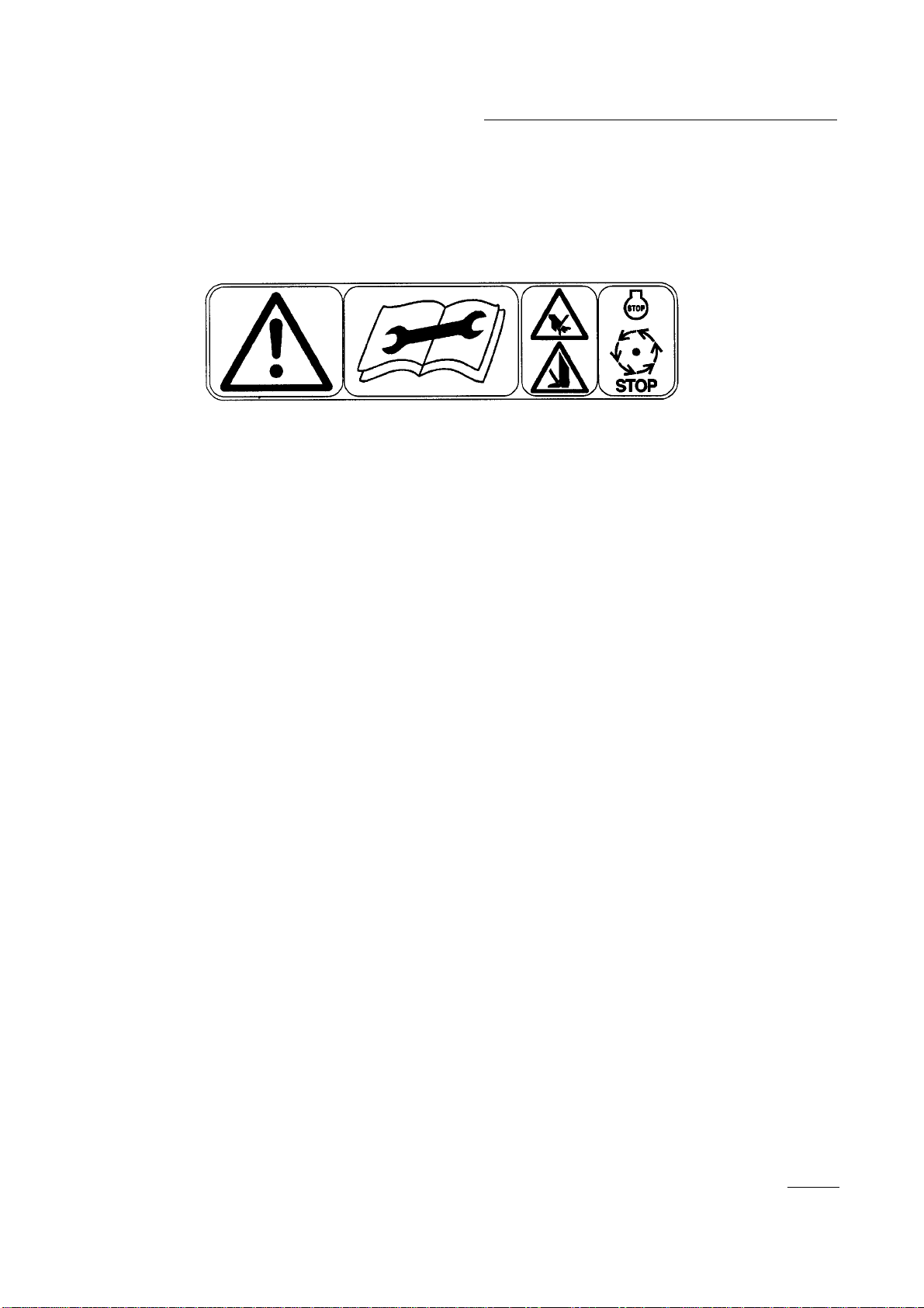
The safety alert symbol means CAUTION, WARNING
or DANGER - “personal safety instruction”. Read and
under stand the instruction because it has to do with
safety. Failure to comply with the instruction may result
in personal injury.
1. Read and understand the contents of this Operator’s
Manual before operating the cutting unit. A free
replacement manual is available by sending
complete Model and Serial Number to:
The Toro Company
8111 Lyndale Avenue South
Bloomington, Minnesota 55420-1196
2. Never allow children to operate the cutting units.
Do not allow adults to operate traction unit or
cutting units without proper instruction. Only
trained operators who have read this manual should
operate the cutting units.
3. Never operate the cutting units when under the
influence of drugs or alcohol.
4. Keep all shields and safety devices in place. If a
shield, safety device or decal is illegible or
damaged, repair or replace it before operation is
commenced. Also tighten any loose nuts, bolts and
screws to assure the cutting unit is in safe operating
condition.
5. Always wear substantial shoes. Do not operate the
cutting unit while wearing sandals, tennis shoes,
sneakers or shorts. Also, do not wear loose-fitting
clothing that could get caught in moving parts.
Always wear long pants and substantial shoes.
Wearing safety glasses, safety shoes and a helmet is
advisable and required by some local ordinances
and insurance regulations.
6. Remove all debris or other objects that might be
picked up and thrown by the cutting unit’s reel
blades. Keep all bystanders away from the mowing
area.
7. If the cutting blades strike a solid object or the
cutting unit vibrates abnormally, stop and shut the
engine off. Check the cutting unit for damaged
parts. Repair any damage before restarting and
operating the cutting unit.
8. Lower the cutting units to the ground and remove
the key from the ignition switch whenever the
machine is left unattended.
9. Be sure cutting units are in safe operating condition
by keeping nuts, bolts and screws tight.
10. Remove the key from the ignition switch to prevent
accidental starting of the engine when servicing,
adjusting or storing the machine.
11. Perform only those maintenance instructions
described in this manual. If major repairs are ever
needed or assistance is desired, contact an
Authorized TORO Distributor.
12. To ensure optimum performance and safety, always
purchase genuine TORO replacement parts and
accessories to keep the Toro all TORO. NEVER
USE “WILL-FIT” REPLACEMENT PARTS AND
ACCESSORIES MADE BY OTHER
MANUFACTURERS. Look for the TORO logo to
assure genuineness. Using unapproved replacement
parts and accessories could void the warranty of
The Toro Company.
Safety Instructions