Power i-Cruise Dial User manual

Instruction Manual

Thank you very much for purchasing "i‑Cruise Dial". In this instruction manual, the
function of i‑Cruise Dial, the wiring method, the operation method, and precautions
for use are written. In order enough to understand the function of i‑Cruise Dial and
to use it safely and effectively, please be sure to use this operation manual with
the directions for use right for your often reading before use.
・
After installation should keep carefully this instruction manual and the wiring diagram
according to vehicle type.
・
i‑Cruise Dial is a parts for race use. Please use it according to regulations, such as the
Road Traffic Law, on a public road.
・
Due to sensitive product, please be careful for using.
・
Since it may change without a preliminary announcement, please understand the appearance of
goods, specification, the price, etc.
Introduction
Table of contents
◇Introduction ・・・・・・・・・・・・・・・・・・・・・・・・・・・・・・・・・・・・・・・・・・・・・・・・・・・・・・・・・・・・・・
◇Table of contents ・・・・・・・・・・・・・・・・・・・・・・・・・・・・・・・・・・・・・・・・・・・・・・・・・・・・・・・・・
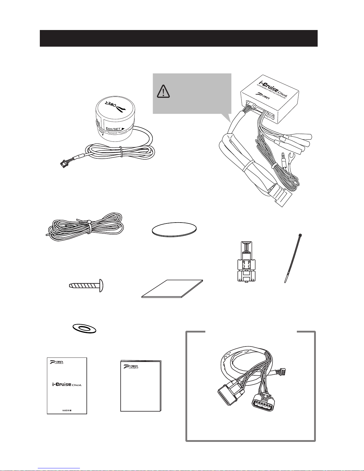
◇Parts list ・・・・・・・・・・・・・・・・・・・・・・・・・・・・・・・・・・・・・・・・・・・・・・・・・・・・・・・・・・・・・・・・
◇A function and the feature ・・・・・・・・・・・・・・・・・・・・・・・・・・・・・・・・・・・・・・・・・・・・・・・・・
◇For use it safely ・・・・・・・・・・・・・・・・・・・・・・・・・・・・・・・・・・・・・・・・・・・・・・・・・・・・・・・・・
◇The wiring method, and installation ・・・・・・・・・・・・・・・・・・・・・・・・・・・・・・・・・・・・・・・・・・・
・Installation notes ・・・・・・・・・・・・・・・・・・・・・・・・・・・・・・・・・・・・・・・・・・・・・・・・・・・・・・・・・・
・Installation schematic view ・・・・・・・・・・・・・・・・・・・・・・・・・・・・・・・・・・・・・・・・・・・・・・・・・・
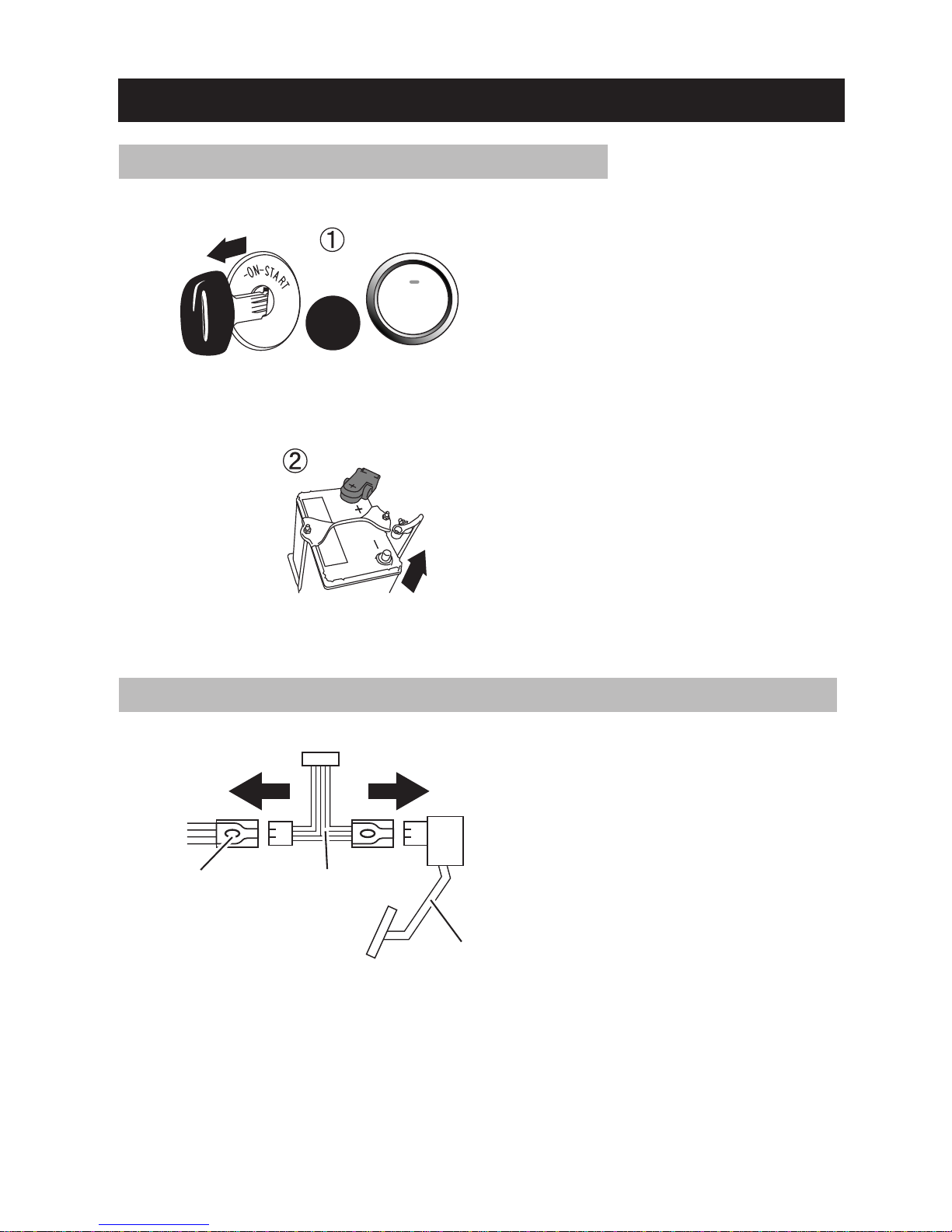
・Installation preparation ・・・・・・・・・・・・・・・・・・・・・・・・・・・・・・・・・・・・・・・・・・・・・・・・・・・・・
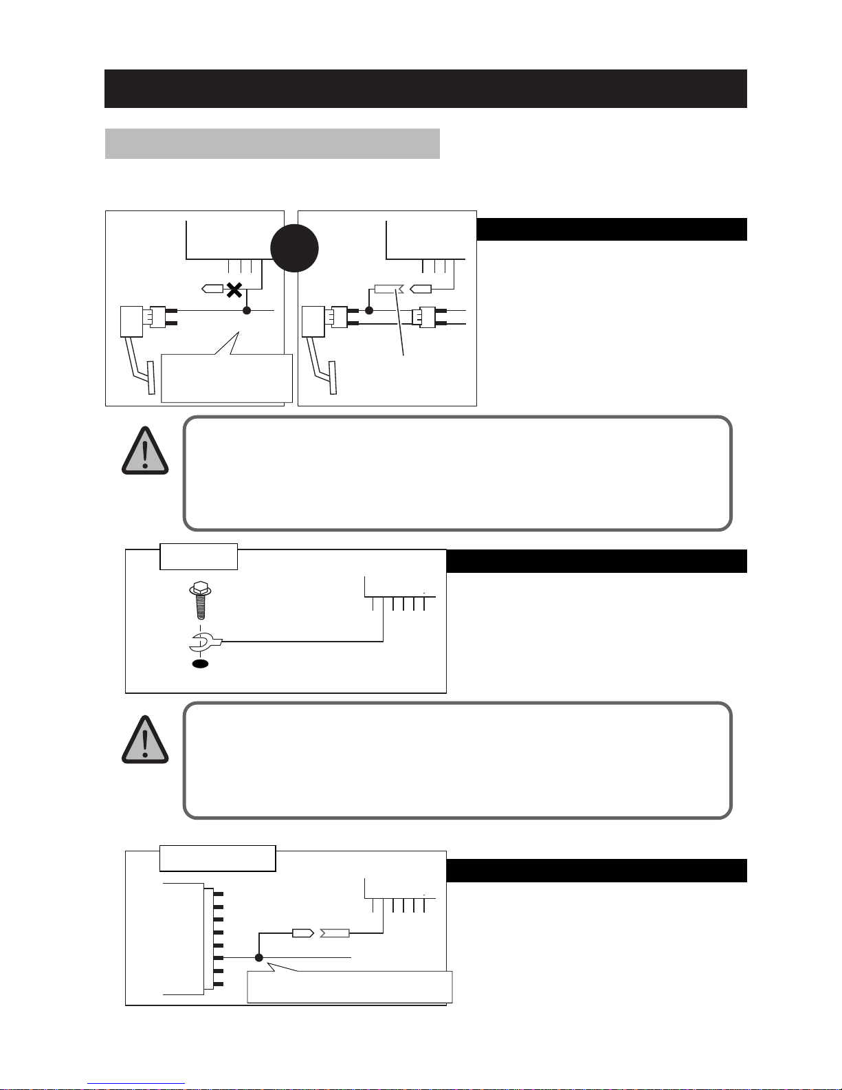
・Installation of the harness according to vehicle type ・・・・・・・・・・・・・・・・・・・・・・・・・・・・・
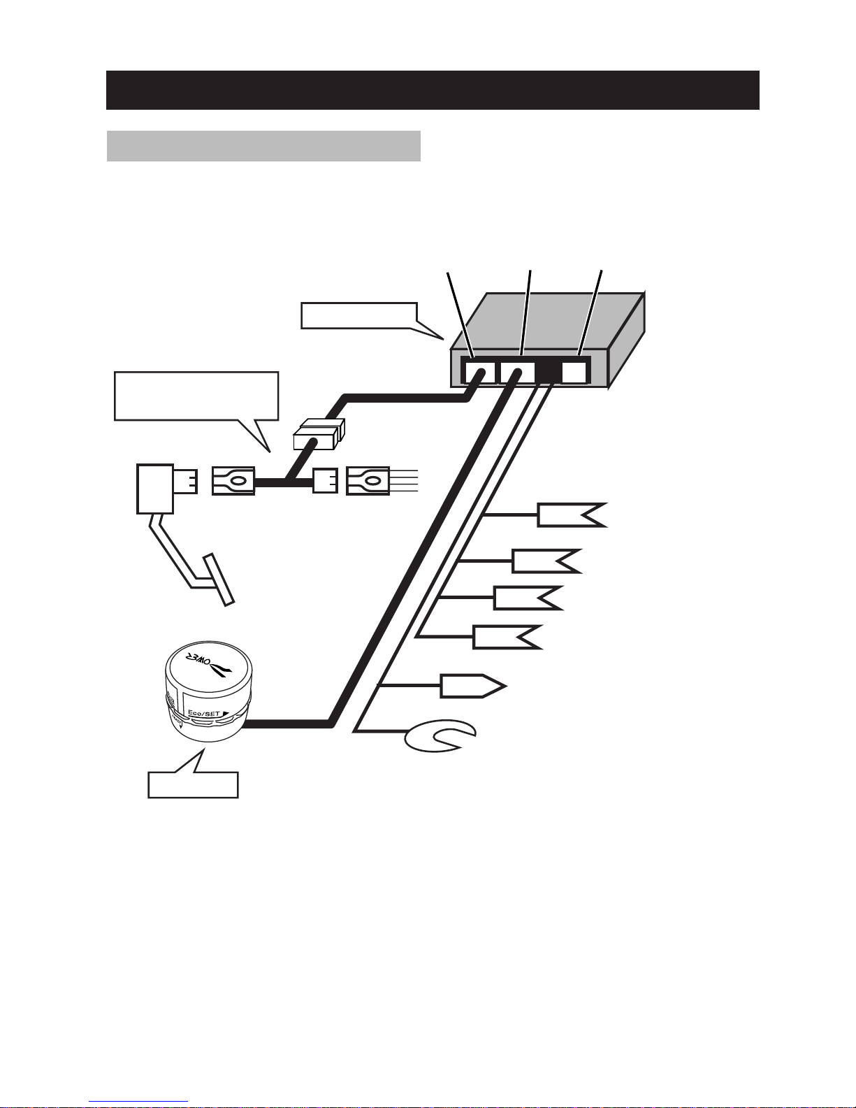
・Each wiring ・・・・・・・・・・・・・・・・・・・・・・・・・・・・・・・・・・・・・・・・・・・・・・・・・・・・・・・・・・・・・・・
・Fixation of a dial unit ・・・・・・・・・・・・・・・・・・・・・・・・・・・・・・・・・・・・・・・・・・・・・・・・・・・・・・・
・Fixation of a main unit ・・・・・・・・・・・・・・・・・・・・・・・・・・・・・・・・・・・・・・・・・・・・・・・・・・・・・・
◇Each part name ・・・・・・・・・・・・・・・・・・・・・・・・・・・・・・・・・・・・・・・・・・・・・・・・・・・・・・・・・・
◇Initial setting 1 <study of an accelerator> ・・・・・・・・・・・・・・・・・・・・・・・・・・・・・・・・・・・・・
◇Checking of operations ・・・・・・・・・・・・・・・・・・・・・・・・・・・・・・・・・・・・・・・・・・・・・・・・・・・・
◇Initial setting 2 <study of speed> ・・・・・・・・・・・・・・・・・・・・・・・・・・・・・・・・・・・・・・・・・・・・
◇A list of operation ・・・・・・・・・・・・・・・・・・・・・・・・・・・・・・・・・・・・・・・・・・・・・・・・・・・・・・・・・
◇The operation method of auto‑cruise ・・・・・・・・・・・・・・・・・・・・・・・・・・・・・・・・・・・・・・・・
・Notes about auto‑cruise ・・・・・・・・・・・・・・・・・・・・・・・・・・・・・・・・・・・・・・・・・・・・・・・・・・・・
・For starting auto‑cruise ・・・・・・・・・・・・・・・・・・・・・・・・・・・・・・・・・・・・・・・・・・・・・・・・・・・・・
・For ending auto‑cruise ・・・・・・・・・・・・・・・・・・・・・・・・・・・・・・・・・・・・・・・・・・・・・・・・・・・・・・
・Acceleration and deceleration under auto‑cruise ・・・・・・・・・・・・・・・・・・・・・・・・・・・・・・・・
・Adjustment of a level (degree of comfort) ・・・・・・・・・・・・・・・・・・・・・・・・・・・・・・・・・・・・・・
◇The operation method of throttle control ・・・・・・・・・・・・・・・・・・・・・・・・・・・・・・・・・・・・・
・The operation method ・・・・・・・・・・・・・・・・・・・・・・・・・・・・・・・・・・・・・・・・・・・・・・・・・・・・・・
・About an effect ・・・・・・・・・・・・・・・・・・・・・・・・・・・・・・・・・・・・・・・・・・・・・・・・・・・・・・・・・・・
◇EcoNavi function ・・・・・・・・・・・・・・・・・・・・・・・・・・・・・・・・・・・・・・・・・・・・・・・・・・・・・・・・・
・About a function ・・・・・・・・・・・・・・・・・・・・・・・・・・・・・・・・・・・・・・・・・・・・・・・・・・・・・・・・・・
◇How to erase an engine check lamp ・・・・・・・・・・・・・・・・・・・・・・・・・・・・・・・・・・・・・・・・・
◇Troubleshooting ・・・・・・・・・・・・・・・・・・・・・・・・・・・・・・・・・・・・・・・・・・・・・・・・・・・・・・・・・・
◇Guarantee ・・・・・・・・・・・・・・・・・・・・・・・・・・・・・・・・・・・・・・・・・・・・・・・・・・・・・・・・・・・・・・・
P1
P1
P2
P3
P5
P6
P6
P7
P8
P8
P9
P11
P12
P13
P15
P16
P18
P20
P21
P21
P22
P23
P24
P26
P27
P27
P27
P29
P29
P30
P31
Back
cover
Installation
Operation
Troubleshooting, others

Please confirm whether there are any insufficient parts before installation.
i‑Cruise Dial
Dial unit (one unit) i‑Cruise Dial
Main unit (one unit)
Double‑stick tape and for main unit
(One sheet)
For a double‑stick tape for dial
(One sheet)
An operation manual
and a guarantee
(one this book)
The wiring diagram
according to vehicle
type (one sheet)
Electro tap
(Two pieces) bundle
(Three pieces)
Cable blue, red, and green
(One bundle each)
Washer
(two sheets)
Tapping screw
(two pieces)
Please see a conformity table and purchase
the harness which suits vehicles.
Harness according to vehicle type (one piece)
Option parts
(it is certainly required.)
Parts list
‑2‑
Relay harness
Although it can detach
and attach, please be
sure to use it,
attaching.
Caution

Auto‑cruise will be started if a dial is left‑clicked during a run. (It functions at
about 30 km/h or more.)
Auto cruise returned to normal drive immediately by pressing a brake pedal or
pushing a dial.
Furthermore, if it turns pushing a dial during auto‑cruise, the acceleration
according to the quantity turned like the accelerator will be carried out.
Moreover, if the right/left‑click of is done without pushing a dial, it can adjust
auto‑cruise speed of ±2 km/h at a time.
Thereby, all of speed change, temporary passing, etc. under auto‑cruise can
make stress there be nothing in a hand.
If auto‑cruise is carried out, even if the setting speed at that time will be
memorized and it will cancel auto‑cruise in a brake etc., if a dial is right‑
clicked after that, after accelerating automatically to a storage speed, it
returns to auto‑cruise speed.
It is a convenient function to return to auto‑cruise again after that, although
the front was got blocked and it slowed down temporarily.
For safety, if less than 50 km/h, resume of the storage speed will not be
eliminated and carried out.
This product does not have a function which controls a brake. Adjustment by
the brake operation of a driver is required only of engine braking on the steep
downward slope which cannot maintain speed.
A heavy‑trafficked way etc. should not use this function in the situation where
between cars cannot fully be maintained. If release is overdue, there is a
possibility of causing a traffic accident.
Neither a freeze nor the time of snow coverage should use this function in the
situation of being easy to slide on a road surface. There is a possibility that a
tire may slip.
Please do not use a shift as Nutral range during auto‑cruise. It will be in an
empty revving‑up state, and if it returns to Drive range after that, there is fear
of sudden acceleration.
When it comes to a downward slope from an uphill, speed may be unable to be
kept constant by change of a driving condition. Be always careful of the speed
meter of vehicles and adjust speed if needed.
A function and the feature
A standard and an auto‑cruise function
Resume auto‑cruise function
‑3‑
Warning
Caution

By click operation of a dial, the accelerator response of vehicles can be
chosen from five patterns. (It is canceled during auto‑cruise.)
According to accelerator valve travel, the lighting color of LED of a dial
changes during a run. In 1 to 60% of accelerator valve travel, it changes to
green, yellowish green, yellow, a sour orange, and red. In 61% or more of valve
travel, it becomes red blink, and blink speed will be three steps early as it
approaches to 100%.
When the power supply of this product is ON, if a brake is stepped on in the
state where the accelerator was stepped on, a throttle will be turned OFF (0%
of valve travel) compulsorily. Even when an accelerator stops returning by a
carpet and a thing being caught in an accelerator etc., vehicles can be slowed
down and stopped certainly.
A function and the feature
Auto throttle control function
EcoNavi function
Accelerator canceler function
In order to enable an accelerator canceler function, please be sure to
connect a brake signal wire.
‑4‑
Normal (power supply OFF)
Eco‑auto Power auto
Power (1)
Power (2)
An accelerator response is in a pure state.
An accelerator response becomes sharper than auto.
It becomes High Response all range.
An accelerator response is the sharpest and becomes sporty.
It becomes a super high response all over the districts.
An accelerator response becomes sharp and
becomes a powerful run.
Moreover, in order to prevent the fuel consumption
aggravation by a superfluous response,
effectiveness condition is self‑adjusted according to
speed.
An accelerator response becomes loose and
supports eco‑operation.
Moreover, effectiveness condition is self‑adjusted
according to speed so that the displeasure in a low
response may not arise.
Caution

General notes
For use it safely
A thing with a possibility that the serious damage for property
or the body may occur.
Athingwithapossibilityofcausing vehicles, breakage,failure of
aproduct,etc.
In using this product, I would like you to certainly know.
In this operation manual, the damage to the property and the body of you or
other persons was prevented, and the matter I would like you to keep in order
to use this product safely and effectively is written with the mark in it.
Please be sure to use it, after that you often read enough understands notes
about the safety shown in this operation manual.
The mark currently used in this book and its meaning are as follows.
Please do not make decomposition or reconstruction of this product
absolute. It becomes failure of a main part and a cause of breakage. Even
if it is within the term of a guarantee, it becomes impossible to perform
repair under warranty, when a visitor performs decomposition and
reconstruction.
The product warranty (this instruction manual back cover) should keep a
store and a specification matter carefully, after entering. Moreover,
please be sure to attach a guarantee in the case of repair. It may
become onerousness when there is no entry of an error of omission or a
store.
Please do not give a strong shock to a product. It becomes a cause of
failure or breakage. Please be careful of the fall at the time of
attachment, etc.
When this product has failure or abnormalities, please stop use immediately and
contactastore orourcompany.
About the accident which uses this product, a breakdown, breakage, and
an illegal act, no responsibility can be taken at our company.
Whenyoulendoutthe vehiclesfurnishedwiththisproductto otherpersons oryou
transfer them, please be sure to be sure to tell me that this product is attached
and to pass this operation manualandguarantee.
‑5‑
Warning
Caution
Caution
Important

Installation notes
The wiring method, and installation
Please do not install to any vehicles other than a conformity vehicle
type. Fault which trouble produces to a run arises, or vehicles may be
damaged and it is dangerous.
Please stop attaching a main part unit and an operation unit to a handle, a shift
lever, a pedal, and the other places that become the hindrance of operation, or
managing wiring. It becomes a cause of an accident and is very
dangerous.
Please install neither a main part unit nor an operation unit a place
humidity and dusty, the place where direct rays hit, the place where it
is filled with heat, near the jet of a heater, etc. It becomes a cause of
discoloration of a main part, modification, malfunction of a product,
failure, or breakage.
Please be sure to extract a key from a key cylinder and to remove the
minus terminal of a battery, when doing wiring work. There are the
breakage of this product, the breakage of vehicles, and fear of a fire by
short‑circuit of wiring, and it is very dangerous.
When the valve of a pure brake lamp is an electric bulb type, please do
not change into an LED type.
Although a brake is stepped on, there is a possibility that the danger
of being unable to cancel auto‑cruise may arise.
Please be sure to use the harness according to vehicle type for
exclusive use for attachment of this product.
The attachment should go in a specialty store. If mistaken wiring is
performed, it will become a cause of serious troubles, such as a
vehicle fire.
When you perform wiring at the place which is easy to be subject to
influences of water, such as an engine room, please be sure to perform
insulated processing and waterproofing processing to a connection
section.
When you take out and insert a connector, please work holding a
connector main part. There is a possibility of disconnecting if harness
is pulled and impossible power is applied.
‑6‑
Warning
Caution

6 pins 7 pins 4 pins (It is not used)
IG power (white)
Ground (black)
Installation schematic view and an installation procedure
Accelerator
Installation schematic view
The harness according
to vehicle type (option)
Main unit
It is not used (yellow).
Reverse signal (green)
Speed signal (blue)
Brake signal (red)
Dial unit
‑7‑

Installation schematic view and an installation procedure
Work procedure (harness installation classified by vehicle type)
‑8‑
The pure connector of
the accelerator upper part is
removed and the harness
according to vehicle type is
connected with an accelerator
at a pure connector.
Accelerator
Harness according
to vehicle type
Pure connector
Please extract an ignition key,
stopping vehicles at an even
place and applying handbrakes
firmly.
Please remove the minus
terminal of a battery.
Please remove the connector of
a pure accelerator and connect
the harness according to vehicle
type (option).
①
②
③
Work procedure (Installation preparation )
ENGINE
START
STOP
Ignition OFF
A key is extracted. Ignition OFF
(Push start type vehicle)
The minus terminal of
a battery is removed.
or

<IG power wire (white)>
Please connect with always 12V
line of the brake switch of the
brake pedal upper part, even if it
has extracted the key.
Grounding wire (black)
Please clench it with a screw,
which intent grounding wire of
body.
<Speed signal (blue)>
It is wiring required in order to
use an auto‑cruise function.
The position of the line which
connects is indicated for the
wiring diagram according to
vehicle type of an attached sheet.
Work procedure (Each wiring)
④ Please perform each wiring according to the following.
At the time of factory shipments, terminal (male) is connected to a power source wire
so that it can connect easily to the commercial harness for brakes.
When you do not use terminal, please cut, and connect with soldering.
Since an electro tap has loose connection's fear, please do not use it for a IG power
wire and a brake line by any means.
When you ground to metal fittings etc., please check that the metal fittings are being
fixed to a body.
It cannot ground by the metal fittings currently fixed to the plastic component etc.
Since the ground to the paint part of a body, etc. becomes the cause that operation is
poor, please avoid it.
black
Ground
It attaches with the bolt
currently fixed to the body etc.
Speed signal
blue
Speed signal
‑9‑
Main unit
The power supply terminal
of regular 12V which have
come out of commercial
option harness
white
Main unit
The brake line of regular 12V
white
tarminal is omitted and
it connects with soldering.
Do not use electro tap
Please set it by using soldering
or electro tap of attached.
Installation schematic view and an installation procedure
or
Main unit
Main unit
Stock ECU
Audio unit
Etc.
Brake Brake
Caution
Caution

Main unit <Brake signal wire (red)>
It is wiring required in order to use
an auto‑cruise function and an
accelerator canceler function.
From the connector of a brake
switch, when you step on a
brake, please connect in search
of the line set to 12V with an
electrical tester etc.
<Reverse signal wire (green)>
It is wiring required in order to
use a back speed assist facility.
When you put into a reverse
gear, please connect with the line
set to 12V.
When you use an auto‑cruise function, in order to cancel auto‑cruise in a
brake, please wire certainly.
Since an electro tap has loose connection's fear, please do not use it for a
brake line (above) and a power source wire (P9) by any means.
If a reverse signal wire is not connected, throttle control and the function
of auto‑cruise will become effective also at the time of retreat.
Please connect a reverse signal wire so that danger, such as jack rabbit
start, does not arise at the time of retreat.
Main unit
Reverse signal
Main unit
‑10‑
Do not use Electro tap.
It connects with soldering.
市販
オプションハーネス
の、ブレーキを踏んで
12Vになる線
The line which steps
on the brake of
commercial option
harness and is set
to 12V
The line set to 12V
when it puts into a
backgear
Exchanges to
male terminal.(*)
(*) Please prepare
male terminal
separately.
Please attach using the electro
tap of soldering or attachment.
Installation schematic view and an installation procedure
Work procedure (Each wiring)
The line set to 12V
when a brake is
stepped on
The line set to 12V
when a brake is
stepped on
or
red red
green
Brake Brake
Caution
Caution

Please wipe off dirt and oil of an
attachment position finely with
clean cloth etc.
Please stick double‑stick tape on
the back of a dial, unite and stick
direction, and fix to a position.
Please put a mark on an
attachment position and remove
the parts which attach from
vehicles.
As shown in the left figure,
please make a screw hole in an
attachment position two places.
Please fix a dial unit using an
attached screw and washer, and
attach parts to vehicles as
before.
①
②
①
②
③
Work procedure(Fixation of a dial unit)
A dial unit has two kinds of fixed methods, double‑stick tape and a screw.
Please choose the suitable fixed method according to an attachment position etc.
‑11‑
To fix with double‑stick tape
To fix with an attached screw
Please carry out attachment to the
part whose thickness is from 2.5
mm to 4.0 mm.
A screw has not become tight with
the thickness besides the above‑
mentioned range, and there is a
possibility that a dial may separate
while in use, by it.
22 mm
Screw hole
4.5 mm in diameter
Installation schematic view and an installation procedure
Important
Important

To Main Part Unit, please
connect. harness according to
vehicle type (six pin connectors)
and dial unit (seven pin
connectors)
Please collect each harness
using bundles not to become the
obstacle of operation.
Please fix to the position which
does not become the obstacle of
operation of a main part unit with
double‑stick tape.
①
②
③
Work procedure (Fixation of a main part)
‑12‑
Harness of
vehicle type
Dial unit harness
Main unit
Please be sure to connect the harness according to vehicle type to relay
harness (Refer to the following figure).
(Please do not remove relay harness from a main unit.)
Please be sure to keep
relay harness connected.
Relay harness
Relay harness
Harness of
vehicle type
Main unit
Installation schematic view and an installation procedure
Caution

Operation method
Name of each part
When you operate this product while a driver operates, be fully
careful not to be looking aside while driving. It becomes a cause of
an accident and is very dangerous.
If these operations are performed under a run and by signal waiting
etc., it will become a cause which cannot respond to sudden operation
but causes an accident.
Only the direction which fully understands the function should perform
operation of this product. If the more nearly other one operates it,
an accident may be caused by accelerating at the times of being
unexpected, such as inside of a run, and it is dangerous.
Please be careful for a child in particular not to operate it enough.
‑13‑
(Display of an auto‑cruise operating state) (The mode / EcoNavi display
of throttle control)
Left‑click operation
A dial is pushed.
Right‑click operation
Clockwise
Counter clockwise
It turns until it is
responsive, and lifts
a hand.
It turns until it is
responsive, and lifts
a hand.
It turns exceeding
a clicking point.
(It turns more than left turn)
It turns exceeding
a clicking point.
Neutral
If a hand is lifted from a dial,
it will certainly return to this position.
The dial itself is pushed
in until it is responsive. LED (green/red)
LED (blue)
Warning

Please turn ON an ignition key (state which the warning lights of meter turn on and the
engine has not put into operation), and check that all LED of a dial unit has disappeared.
When blue LED is blinking, please let me put out the light by pushing a dial.
When red / green LED is on, please let me put out the light by click operation of a dial.
①
Initial‑setting 1.<Study of an accelerator>
After installation should perform study of an accelerator, and
study (P18) of speed at any cost.
i‑Cruise Dial is made to learn about the characteristic of a pure accelerator first.
If the power supply of this product is turned ON, without performing this study, an engine
check lamp lights up and it cannot run normally.
In addition, if it is made to learn once, even if it removes i‑Cruise Dial, and it removes a
battery terminal, there is no necessity for re‑study as long as it uses it by the same vehicles.
‑14‑
Please continue pushing a dial.
(Although blue LED lights up in about 5
seconds, please continue pushing as it
is.)
If blue LED lights up, please turn to the
right until it is responsive, with a dial
pushed and lift a hand.
Blue LED goes out and green LED blinks.
①
②
Please continue
pushing until blue
LED lights up.
(For about 5 seconds)
If blue LED lights up,
it will right‑click
pushed.
If a hand is
lifted, green LED
will blink.
(Blue LED goes out)
↓next page is followed.
ENGINE
START
STOP
A key is turned to
Ignition ON. Please push button
twice, without stepping
on a brake
(push start type vehicle).
Putting out lights
or
Caution

Initial‑setting 1.<study (continuation of the last page) of an accelerator>
‑15‑
Where a foot is taken off an accelerator,
please push a dial once.
Blink of green LED changes to blink of
red LED.
Where an accelerator is broken in
completely, please push a dial once.
LED of a dial unit goes out.
④
⑤
⑥
⑦
Green blink
changes to
red blink.
Please push
a dial once.
Please push
a dial once.
Putting out lights
Study of an accelerator is completion in the above operation.
Please take a foot
off an accelerator.
An accelerator is
broken in to the back.

Operations check
Please turn ignition ON (state which the
warning lights of meter turn on and the
engine has not work), and check that
LED of a dial unit has gone out.
・ When blue LED is blinking, please push dial,
and turn off the light.
・ When red / green LED is on, please click
dial, and turn off the light.
Please start engine, and step on
accelerator lightly.
Please check that an accelerator reacts
as usual and there are no abnormalities,
such as lighting of an engine check lamp.
Please lift a hand in the place which
turned the dial to the left until it is
responsive, and check that green LED
lights up.
Please check that accelerator reacts as
usual, and there are no abnormalities,
such as lighting of an engine check lamp
when accelerator is stepped lightly.
Please check operations after installation as follows.
Please interrupt checking operations when some abnormalities arise, and
remove a cause of troubles by following troubleshooting P31 .
①
②
③
ENGINE
START
STOP
Please step on the accelerator, with the engine started and check whether engine RPM changes.
When there is any changes, please check that it is not forgotten whether to install stock parts
which were removed in addition to this product.
When there is not any changes, please check whether there is any error in wiring according to
vehicle type.
Please turn off check lamp after a check (P30), and redo from the checking of operations ①
once again.
When an engine check lamp lights up ...
‑16‑
Green lighting
↓next page is followed.
A key is turned to
Ignition ON. Please push button
twice, without stepping
on a brake
(push start type vehicle).
or
Putting out lights
Please step on accelerator lightly.

Operations check (continuation of the last page)
Please run.
Please check that there are no
abnormalities, such as that there are no
abnormalities in the action of a car and
lighting of an engine check lamp.
④
Study of an accelerator may not be completed normally. Please erase an engine check
lamp (P30) and learn an accelerator once again (P14).
When an engine check lamp lights up ...
Study of an accelerator may not be completed normally. Please erase an engine check
lamp (P30) and learn an accelerator once again (P14).
When an engine check lamp lights up ...
‑17‑

Please turn on an ignition key (state which the warning lights of meter turn on
and the engine doesn't work), and check that all LED of a dial unit are turned off.
When blue LED is blinking, please let me put out the light by pushing a dial.
When red / green LED is on, please let me put out the light by click operation of a dial.
①
Initial‑setting 2.<study of speed>
Please perform study of accelerator and speed signal after
installation.
i‑Cruise Dial is made to learn the characteristic of a pure speed signal.
If this product is used without performing this study, the functions, such as auto‑
cruise, will not operate normally.
In addition, if it is made to learn once, even if it removes i‑Cruise Dial, and it
removes a battery terminal, there is no necessity for re‑study as long as it uses it
by the same vehicles.
‑18‑
Please continue pushing a dial.
(Although blue LED lights up in about 5
seconds, please continue pushing as it is.)
If blue LED lights up, please turn to the
left, with a dial pushed and lift a hand
until it is responsive.
Blue LED is blinked.
②
③
If blue LED lights up,
please left‑click.
If a hand is lifted,
blue LED will blink.
↓next page is followed.
ENGINE
START
STOP
A key is turned to
Ignition ON. Please push button
twice, without stepping
on a brake
(push start type vehicle).
Putting out lights
or
Please continue
pushing until blue
LED lights up.
(For about 5 seconds)
Caution

Initial‑setting 2.<study (continuation of the last page) of speed>
‑19‑
Please maintain speed 60 km/h and push
a dial in the state.
A setup is completion when blue LED
disappears, after lighting up for about 1
second.
Study is failure when disappearing, after
red LED blinks 3 times.
Please redo stetting from ① once again,
and please try to learn at a higher speed.
④
⑤
Blue LED lighting
(for 1 second) ‑>
putting out lights
Please push
dial once.
The completion of a setting
Redo setting
Three red LED blinks
(60km/h)
Table of contents