PowerBoss C82 User manual

Commander C Series PB# 4100040UM Rev.B 04/12
PowerBoss, Inc. Copyright 2012
Page 1
User Manual
Commander C Series
Models: C82, C82 Europe, & C90
Gasoline, LP & Diesel
PowerBoss, Inc.
A Member Of The Hako Group
PB# 4100040UM Rev. B 04/12

PowerBoss, Inc. Copyright 2012
Commander C Series PB# 4100040UM Rev.B 04/12
Page 2
PREFACE
Thank you for your purchase of the now industry standard for sweepers. PowerBoss takes great pride in
offering the most dependable, reliable and best value in industrial power sweepers and sweeper / scrubbers.
We set the standard.
Our Publishing Department would like to hear from you. If you see any errors, omissions or something that
needs clarication in this User Manual please let us know. We are working hard toward perfection in our corner
of the process to bring you the best you can buy. Please copy the form below, ll out and comment on how you
found our catalog.
Thank you.
*Name______________________________________________________________________
*Title: ______________________________________________________________________
*Company Name: _____________________________________________________________
*Address: ____________________________________________________________________
*Country: ____________________________________________________________________
Type of equipment or model number: ______________________________________________
PREFACE

Commander C Series PB# 4100040UM Rev.B 04/12
PowerBoss, Inc. Copyright 2012
Page 3
Comments:
*Information is optional.
Please return to:
Manager, Publishing Department, International
PowerBoss, Inc.
175 Anderson Street
Aberdeen, North Carolina 28315 USA
Phone (800) 982-7141 Toll Free
(910) 944-2105 Local
E-Mail - [email protected]
PREFACE

PowerBoss, Inc. Copyright 2012
Commander C Series PB# 4100040UM Rev.B 04/12
Page 4
This is the User Manual for the PowerBoss Commander C Series Sweeper Scrubber.
This manual covers all Standard Commander C Series machine variations beginning May 2009.
We believe this machine will provide excellent service for many years.
However, the best results will be obtained if:
• The machine is operated with reasonable care.
• The machine is maintained regularly per the maintenance schedule provided in the User Manual.
• The machine is maintained with PowerBoss Inc. supplied or equivalent parts.
All right side and left side references to the machine (except for engine) are determined by facing the direction
of forward travel. The front of the engine or engine fan faces the rear of the machine. Some hardware
considered to be common or locally available has been omitted from the parts section to make this manual
clear. Be sure to use equivalent hardware when replacement becomes necessary.
The Model and Serial Number of your machine is shown on the I.D. name plate. This information is needed
when contacting Technical Support or when ordering parts. The I.D. plate is mounted on the console of the
machine left of the operator and adjacent the main broom adjustment access door.
Parts may be ordered by phone,fax or e-mail from any PowerBoss parts and service center. Before
ordering parts or supplies, be sure to have your machine model number and serial number handy. For your
convenience Fill out the data block below for future reference.
PREFACE

Commander C Series PB# 4100040UM Rev.B 04/12
PowerBoss, Inc. Copyright 2012
Page 5
Example I.D Plate;
MACHINE DATA
Fill out at installation
Serial Number: ___________________________________
Engine Serial Number: ____________________________
Sales Rep.: ______________________________________
Date of Install: ___________________________________
All information contained in this catalog is current at the time of printing However, PowerBoss reserves the
right to make changes at any time without notice.
©2012, PowerBoss, Inc., Printed in USA
PREFACE

PowerBoss, Inc. Copyright 2012
Commander C Series PB# 4100040UM Rev.B 04/12
Page 6
TECHNICAL SPECIFICATIONS
Model Commander C Series
Model No. CSS90DSL / CSS90DSLBR / CSS90LP / CSS90LPBR / 3310500 / 3310500BR / 3333680 /
3333680BR / 3333750 / 3333750BR / 3333815 / 3333815BR / CSS82DSLCE / CSS82LPCE
DIMENSIONS & WEIGHT
C82 & C82 Europe C90
Length . . . . . . . . . . . . . . . . . . . 95.5 inch (243 cm) . . . .98 inch (249 cm)
Length w/ side broom . . . . . . . 109 inch (277 cm) . . . . .111.5 inch (283 cm)
Width . . . . . . . . . . . . . . . . . . . . 53 inch (135 cm) . . . . . .59 inch (150 cm)
Width w/ side broom . . . . . . . . 56 inch (142 cm) . . . . . .62 inch (158 cm)
Height . . . . . . . . . . . . . . . . . . . 57 inch (145 cm) . . . . . .63 inch (160 cm)
Height w/ overhead guard . . . 87 inch (221 cm) . . . . . .87 inch (221 cm)
Height w/ cab. . . . . . . . . . . . . . 83.5 inch (212 cm) . . . .83.5 inch (212 cm)
Weight . . . . . . . . . . . . . . . . . . 2700 lbs (1225 kg). . . . .3000 lbs (1361 kg)
Minimum U-turn. . . . . . . . . . . . 96 inch (244 cm) . . . . . .101 inch (256.5 cm)
TECHNICAL SPECIFICATIONS
SWEEPING SYSTEM
C82 & C82 Europe C90
Sweep path . . . . . . . . . . . . . . . 42 inch (107 cm) . . . . . .48 inch (122 cm)
Sweep Path W/ side broom. . . 54 inch (137 cm) . . . . . .60 inch (152 cm)
Main broom . . . . . . . . . . . . . . . 42 inch (107 cm) . . . . . .48 inch (122 cm)
Side broom . . . . . . . . . . . . . . . optional . . . . . . . . . . . . .optional
Hopper type. . . . . . . . . . . . . . . manual dump . . . . . . . .manual dump
Hopper volume . . . . . . . . . . . . 5 cu ft . . . . . . . . . . . . . .6 cu ft
Hopper load capacity. . . . . . . . 200 lbs (91 kg) . . . . . . .250 lbs (113 kg)
SCRUBBING SYSTEM
Scrub path . . . . . . . . . . . . . . . . 42 inch (107 cm) . . . . . .48 inch (122 cm)
Scrub deck pressure . . . . . . . . 300 lbs (136 kg) . . . . . .300 lbs (136 kg)
Brush speed . . . . . . . . . . . . . . 250 rpm . . . . . . . . . . . . .250 rpm
Solution tank capacity . . . . . . . 68 gal (257 L) . . . . . . . .100 gal (378.5 L)
Recovery tank capacity . . . . . . 65 gal (246 L) . . . . . . . .100 gal (378.5 L)
Squeegee width. . . . . . . . . . . . 44 inch (112 cm) . . . . . .50 inch (127 cm)

Commander C Series PB# 4100040UM Rev.B 04/12
PowerBoss, Inc. Copyright 2012
Page 7
TECHNICAL SPECIFICATIONS

PowerBoss, Inc. Copyright 2012
Commander C Series PB# 4100040UM Rev.B 04/12
Page 8
CE DECLARATION OF CONFORMITY
COMMANDER C82
DECLARATION OF CONFORMITY

Commander C Series PB# 4100040UM Rev.B 04/12
PowerBoss, Inc. Copyright 2012
Page 9
DECLARATION OF CONFORMITY

PowerBoss, Inc. Copyright 2012
Commander C Series PB# 4100040UM Rev.B 04/12
Page 10
TABLE OF CONTENTS
PREFACE .............................. 2
TECHNICAL SPECIFICATIONS. . . . . . . . . . . . . 6
DIMENSIONS & WEIGHT ........................6
SWEEPING SYSTEM ........................... 6
SCRUBBING SYSTEM . . . . . . . . . . . . . . . . . . . . . . . . . . 6
CE DECLARATION OF CONFORMITY . . . . . . . 8
COMMANDER C82 . . . . . . . . . . . . . . . . . . . . . . . . . . . . . 8
FEATURES . . . . . . . . . . . . . . . . . . . . . . . . . . . . . 15
AIR-MOVING SYSTEM . . . . . . . . . . . . . . . . . . . . . . . . . . 15
ERGONOMICS SYSTEM ........................ 15
DEBRIS-HANDLING SYSTEM .................... 15
DRIVE-TRAIN SYSTEM ......................... 15
CHASSIS SYSTEM . . . . . . . . . . . . . . . . . . . . . . . . . . . . . 15
ENVIRONMENTAL FRIENDLY FEATURES . . . . . . . . . . 16
WATER CONSERVATION .................... 16
CLEAN AIR ................................ 16
LOWER EMISSIONS. . . . . . . . . . . . . . . . . . . . . . . . . 16
SAFER WORK ENVIRONMENT ................ 16
CLEAN ENERGY ............................ 16
SAFETY INFORMATION . . . . . . . . . . . . . . . . . . 17
IMPORTANT SAFETY INSTRUCTIONS. . . . . . . . . . . . . 17
FOR SAFETY DURING OPERATION. . . . . . . . . . . . . . . 17
FOR SAFETY WHEN SERVICING OR MAINTAINING
MACHINE ....................................18
SAFETY SYMBOLS ............................18
SAFETY DECALS. . . . . . . . . . . . . . . . . . . . . . . . . . . . . . 19
BASIC POWERBOSS® SAFETY. . . . . . . . . . . . 22
TABLE OF CONTENTS

Commander C Series PB# 4100040UM Rev.B 04/12
PowerBoss, Inc. Copyright 2012
Page 11
MACHINE OPERATION . . . . . . . . . . . . . . . . . . . 25
BASIC OPERATING CONTROLS AND INDICATORS 25
IGNITION SWITCH .......................... 25
HORN ....................................25
LIGHT SWITCH . . . . . . . . . . . . . . . . . . . . . . . . . . . . . 25
HOUR METER. . . . . . . . . . . . . . . . . . . . . . . . . . . . . . 25
ENGINE COOLANT TEMPERATURE GAUGE . . . . . 25
FUEL LEVEL GAUGE ........................ 25
ENGINE OIL PRESSURE ..................... 26
VOLTMETER AMP GAUGE ....................26
THROTTLE (DIESEL) ........................ 26
MURPHY SWITCH (DIESEL ONLY) ............. 26
GLOW PLUG BUTTON (DIESEL ONLY). . . . . . . . . . 26
PARKING BRAKE ........................... 28
BRAKE ....................................28
SEAT ADJUSTMENT. . . . . . . . . . . . . . . . . . . . . . . . . 28
THROTTLE (GAS AND LP) .................... 28
CHECK ENGINE INDICATOR
(GAS AND LP ONLY). . . . . . . . . . . . . . . . . . . . . . . . . 28
SWEEPING AND SCRUBBING CONTROLS. . . . . . . . . 31
BROOM CONTROL LEVER . . . . . . . . . . . . . . . . . . . 31
MAIN BROOM HANDLE ...................... 31
SIDE BROOM HANDLE ......................31
SCRUB HEAD SWITCH ......................33
SCRUB DECK GAUGE . . . . . . . . . . . . . . . . . . . . . . . 33
SQUEEGEE SWITCH ........................ 33
SOLUTION LEVER .......................... 33
SOLUTION TANK EMPTY INDICATOR. . . . . . . . . . . 33
RECOVERY TANK FULL INDICATOR ............ 33
IMPELLER LEVER ..........................33
OPTIONAL CONTROLS . . . . . . . . . . . . . . . . . . . . . . . . . 34
WATER RECYCLING ........................34
Cleaning solution control knob . . . . . . . . . . . . . . . 34
Pump 1 switch ........................... 34
Pump 2 switch ........................... 34
OPERATING THE WATER RECYCLING
SYSTEM ..................................34
TABLE OF CONTENTS

PowerBoss, Inc. Copyright 2012
Commander C Series PB# 4100040UM Rev.B 04/12
Page 12
OPERATING PROCEDURES . . . . . . . . . . . . . . . . . . . . . 36
PRE-OPERATION CHECKS . . . . . . . . . . . . . . . . . . . 36
STARTING . . . . . . . . . . . . . . . . . . . . . . . . . . . . . . . . . 36
Gasoline or LP Power Units . . . . . . . . . . . . . . . . . 36
Diesel Power Units ........................ 37
TRAVELING FORWARD OR BACKWARDS. . . . . . . 37
Forward ................................37
Reverse ................................ 37
SLOWING AND STOPPING ................... 37
SWEEPING ................................ 38
REMOVING AND DUMPING HOPPER. . . . . . . . . . . 38
SCRUBBING ............................... 39
Operating the Scrub Brushes ................ 39
Starting Solution Flow . . . . . . . . . . . . . . . . . . 39
Lower The Squeegee . . . . . . . . . . . . . . . . . . . 39
FILLING THE SOLUTION TANK ................ 40
DRAINING THE RECOVERY TANK ............. 41
CLEANING THE RECOVERY TANK . . . . . . . . . . . . . 42
SQUEEGEE WAND (OPTION) ................. 43
BLOWER (OPTION) .........................43
TRANSPORTING THE MACHINE. . . . . . . . . . . . . . . 44
Using a Trailer or Transport Vehicle . . . . . . . . . . . 44
Pushing the Machine ......................44
PREVENTATIVE MAINTENANCE . . . . . . . . . . . 45
INTRODUCTION . . . . . . . . . . . . . . . . . . . . . . . . . . . . . . . 45
SCHEDULED MAINTENANCE CHART . . . . . . . . . . . . . 46
PREVENTATIVE MAINTENANCE INSTRUCTIONS 50
ENGINE . . . . . . . . . . . . . . . . . . . . . . . . . . . . . . . . . . . 50
Air Intake System . . . . . . . . . . . . . . . . . . . . . . . . . 50
Check Air Filter Service Indicator . . . . . . . . . . 50
Air Filter Element Removal. . . . . . . . . . . . . . . 51
Air Filter Cleaning. . . . . . . . . . . . . . . . . . . . . . 52
Air Filter Inspection. . . . . . . . . . . . . . . . . . . . . 52
Air Filter Installation .................... 52
ELECTRICAL SYSTEM ...................... 52
Battery Cleaning. . . . . . . . . . . . . . . . . . . . . . . . . . 52
Battery Replacement ......................53
Circuit Breaker . . . . . . . . . . . . . . . . . . . . . . . . . . . 53
Fuses . . . . . . . . . . . . . . . . . . . . . . . . . . . . . . . . . . 54
FUEL SYSTEM . . . . . . . . . . . . . . . . . . . . . . . . . . . . . 54
TABLE OF CONTENTS

Commander C Series PB# 4100040UM Rev.B 04/12
PowerBoss, Inc. Copyright 2012
Page 13
COOLANT SYSTEM. . . . . . . . . . . . . . . . . . . . . . . . . 56
Blowing Out Radiator Fins . . . . . . . . . . . . . . . . . . 56
Reverse Flow Flushing. . . . . . . . . . . . . . . . . . . . . 56
LUBRICATION . . . . . . . . . . . . . . . . . . . . . . . . . . . . . . 57
Changing Engine Oil ...................... 57
LUBRICATION POINTS ...................... 57
Steering Fork Assembly and Steering Link Ball Joints. .
57
Steering Cylinder .........................58
Latches & Hinges . . . . . . . . . . . . . . . . . . . . . . . . . 58
HYDRAULICS SYSTEM . . . . . . . . . . . . . . . . . . . . . . 59
Filling The Fluid Reservoir ..................59
Hydraulic Fluid Viscosity Specications . . . . . 59
Maintaining Hydraulic Oil Cooler Efciency . . . . . 59
Changing The Hydraulic Fluid ............... 60
Changing The Hydraulic Fluid Filter. . . . . . . . . . . 60
SWEEP COMPONENTS . . . . . . . . . . . . . . . . . . . . . . 61
Broom Door Flap Inspection ................61
Broom Door Flap Replacement and Adjustment 61
Main Broom Pattern Check ................. 62
Main Broom Height Adjustment .............. 63
Main Broom Taper Adjustment . . . . . . . . . . . . . . . 64
Main Broom Replacement .................. 65
Side Broom Angle Adjustment ............... 66
Side Broom Height (Wear) Adjustment ........ 67
Side Broom Lift Cable Adjustment ......... 68
Side Broom Replacement . . . . . . . . . . . . . . . . . . 68
SCRUB & WATER PICK-UP COMPONENTS . . . . . . 69
Scrub Brush Replacement . . . . . . . . . . . . . . . . . . 69
Scrubhead Gauge Adjustment . . . . . . . . . . . . . . . 69
Scrubhead Adjustment . . . . . . . . . . . . . . . . . . . . . 70
TABLE OF CONTENTS

PowerBoss, Inc. Copyright 2012
Commander C Series PB# 4100040UM Rev.B 04/12
Page 14
MAIN SQUEEGEE COMPONENTS . . . . . . . . . . . . . 72
CHECKING and Adjusting the Rear Main Squeegee
Flare . . . . . . . . . . . . . . . . . . . . . . . . . . . . . . . . . . . 72
Turning or Replacing the Rear Squeegee Blade 74
Main Squeegee Tool Removal . . . . . . . . . . . . . . . 74
Main Squeegee Tool Installation .............75
Inner Squeegee Replacement . . . . . . . . . . . . . . . 75
Auto Squeegee Lift Mechanism . . . . . . . . . . . . . . 75
HOPPER .................................. 76
Flap Replacement ........................ 76
Floor Clearance ..........................76
Frame Seal Replacement ..................76
Front Frame Seal ......................76
Side Frame Seal. . . . . . . . . . . . . . . . . . . . . . . 76
PARKING BRAKE ........................... 77
Adjusting The Parking Brake Cable Length . . . . . 77
Cable Adjustment for Standard brake ......... 77
CHANGING SOLID TIRES ....................78
Front Tire ............................... 78
Rear Tire ...............................78
MISCELLANEOUS ADJUSTMENTS . . . . . . . . . . . . . 78
Anti-Static Chain Adjustment ................ 78
Latch and Hinge Maintenance . . . . . . . . . . . . . . . 78
Cables .................................78
TROUBLESHOOTING . . . . . . . . . . . . . . . . . . . . 79
TROUBLESHOOTING CHART . . . . . . . . . . . . . . . . . . . . 79
NOTES ................................ 87
WARRANTY ............................ 88
TABLE OF CONTENTS

Commander C Series PB# 4100040UM Rev.B 04/12
PowerBoss, Inc. Copyright 2012
Page 15
FEATURES
AIR-MOVING SYSTEM
• Shock-mounted hydraulic impeller
• Engine area shielded from exhaust air
ERGONOMICS SYSTEM
• Roomy, open cockpit with extra comfort
• Adjustable, high-back seat with arm rests
• Power steering
• Comfortable pedal/controls placement
• Full instrumentation for all functions
DEBRIS-HANDLING SYSTEM
• Direct throw sweeping method
• Quick-change, oating 42” main broom &
retractable side brooms
• Dual-performance sweep mode
DRIVE-TRAIN SYSTEM
• Industrial liquid-cooled engine
• Heavy-duty radiator & Tri-phase air cleaner
• Hydraulics protection package
• 4-Core Radiator
• Industrial smooth ride tires for traction and
reliability
CHASSIS SYSTEM
• Massive One-Piece, unitized steel frame
FEATURES

PowerBoss, Inc. Copyright 2012
Commander C Series PB# 4100040UM Rev.B 04/12
Page 16
FEATURES
ENVIRONMENTAL FRIENDLY FEATURES
WATER CONSERVATION
Aqua-Stop saves water usage by 50%, water is
released through a pump system providing greater
control of water usage than gravity systems
CLEAN AIR
High-performance lter system dramatically reduces
the release of dust and debris back into the air, dust
vacuum ensures that dust is put directly into the
hopper, bristle pattern on main broom increases dust
control.
LOWER EMISSIONS
All gas and LP engines meet Tier 2 specications,
catalyst mufers, battery operated available, diesel
operated available, bio-diesel fuel can be used in
Kubota engine
SAFER WORK ENVIRONMENT
Orange machines are highly visible to others in the
workplace, simple controls reduce operator error,
one-button scrub, horn, re in hopper indicator,
effective braking system, “belly bar” prevents
operator from being pinned behind machine when
in reverse, parabolic squeegee picks up all water
leaving the scrub path virtually dry for trafc, seat
equipped with safety shut-off switch, also available:
overhead guard, back-up alarm, warning beacon
CLEAN ENERGY
Bio-diesel fuel can be used in Kubota engines
CLEAN ENERGY
Aqua-Stop saves chemical usage by 50%, pump
system for water and chemical release allows for
better control of chemical usage, chemical metering
system is available as an option and regulates
chemical usage to the correct dose.

Commander C Series PB# 4100040UM Rev.B 04/12
PowerBoss, Inc. Copyright 2012
Page 17
SAFETY INFORMATION
IMPORTANT SAFETY INSTRUCTIONS
Operators must read and understand this manual
before operating or maintaining this machine.
Do not operate this machine in ammable or
explosive areas.
This machine is designed solely for removing dirt,
dust and debris in an outdoor or indoor environment.
PowerBoss does not recommend using this
machine in any other capacity.
The following information below may cause a
potential hazard to the operator and equipment.
Read this manual carefully and be aware when
these conditions can exist. Take necessary steps to
locate all safety devices on the machine and train
the personnel operating the machine. Report any
machine damage or faulty operation immediately.
Do not use machine if it is not in proper operating
condition.
FOR SAFETY DURING OPERATION
Keep hands and feet clear of moving parts while machine is
in operation.
Make sure all safety devices are in place and operate
properly. All covers, doors and latches must be closed and
fastened before use.
During operation, attention should be paid to other persons
in the work area and especially if small children are present.
Components can cause an explosion when operated near
explosive materials or vapor. Do not operate this machine
near ammable materials such as solvents, thinners, fuels,
grain dust, etc.
Store or park this machine on a level surface only. To
prevent unauthorized use, machine should be stored or
parked with the key removed.
This machine is designed for level operation only. Do not
operate on ramps or inclines greater than 2%.
This machine is not suitable for picking up hazardous dusts.
Use caution when moving this machine into areas that are
below freezing temperatures.
SAFETY INFORMATION

PowerBoss, Inc. Copyright 2012
Commander C Series PB# 4100040UM Rev.B 04/12
Page 18
FOR SAFETY WHEN SERVICING OR
MAINTAINING MACHINE
Stop on level surface.
Disconnect the power to the machine when servicing.
Avoid moving parts. Do not wear loose jackets, shirts,
or sleeves when working on machine.
Avoid contact with battery acid. Battery acid can
cause burns. When working on or around batteries,
wear protective clothing and safety glasses. Remove
metal jewelry. Do not lay tools or metal objects on top
of battery.
Authorized personnel must perform repairs and
maintenance. Use PowerBoss supplied replacement
parts.
SAFETY SYMBOLS
Five symbols are used throughout this manual to
emphasize various levels of safety information. These
symbols and the meaning of each are listed below.
DANGER
To warn of immediate hazards which will result in
severe personal injury or death
WARNING
To warn of hazards or unsafe practices which
could result in severe personal injury or death.
CAUTION
To warn of hazards or unsafe practices which
could result in minor personal injury.
ATTENTION!
To warn of practices which could result in
extensive equipment damage.
NOTE: To direct your attention to important
equipment information or special
instructions for preventing damage to
equipment
SAFETY INFORMATION

Commander C Series PB# 4100040UM Rev.B 04/12
PowerBoss, Inc. Copyright 2012
Page 19
Symbols at the top of the list are the strongest
warnings. However, all symbols represent important
information which should be observed to protect
you and others from harm and injury, and to prevent
damage to the equipment.
SAFETY DECALS
Decals directly attached to various parts of the unit
are highly visible safety reminders which should
be read and observed. Make sure the decals are
replaced if they become illegible or damaged.
Located in the drive compartment:
Part Number 301854
SAFETY INFORMATION

PowerBoss, Inc. Copyright 2012
Commander C Series PB# 4100040UM Rev.B 04/12
Page 20
Located at the Impeller:
Part Number 301729
Located on the shroud of the radiator:
Part Number 301733
SAFETY INFORMATION
This manual suits for next models
1
Table of contents
Other PowerBoss Blower manuals

PowerBoss
PowerBoss Armadillo 9X User manual

PowerBoss
PowerBoss Admiral 38 Installation and operation manual

PowerBoss
PowerBoss apex 47 g User manual

PowerBoss
PowerBoss PB620DSL User manual

PowerBoss
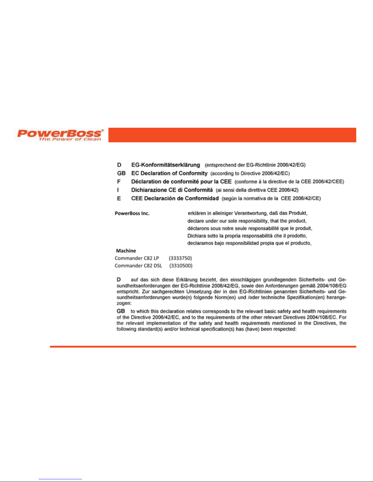
PowerBoss 82 Europe User manual

PowerBoss
PowerBoss armadillo 10x series User manual

PowerBoss
PowerBoss Armadillo 9X Series User manual

PowerBoss
PowerBoss Armadillo SW/9XR User manual