PowerBox Systems iGyro SAT User manual

Instruction Manual

2PowerBox-Systems − World Leaders in RC Power Supply Systems
The iGyro SAT converts the PBR-7S, PBR-9D and PBR-26D into an outstanding
gyro system. In this conguration the iGyro SAT operates as the sensor unit for the
receiver. The gyro software has been developed from the ground up for the iGyro
3xtra, and this is now an integral feature of the receivers. The result is that the pilot
obtains an unprecedented level of performance for a gyro system integrated into
a receiver.
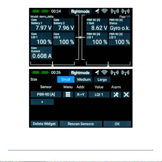
A further advantage is that all the set-up procedures can be carried out entirely
from the transmitter - thanks to the CORE transmitter’s powerful telemetry system.
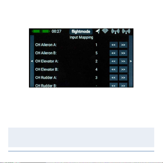
Setting up the system involves three fundamental points: channel assignment, de-
tection of installed orientation, and establishing the end-points. Supplementary fea-
tures such as gyro characteristics, stick priority and lock-in feel also give experts
the means to customise the iGyro SAT to their exact personal requirements.
There is yet another very important advantage to mention: if a GPS II Sensor is
connected to the P²BUS as a telemetry sensor in the usual way, it delivers the
airspeed information needed by the receiver’s integral gyro in order to adjust gyro
gain in relation to the model’s airspeed!
2. INSTALLATION, CONNECTIONS
The iGyro SAT can be installed in any position in the model - provided that it is
parallel to or at right-angles (90°) to the model’s centreline (direction of ight). The
result of installing it at an angle would be a mixed corrective effect. For example:
a gust affecting the aileron axis might cause the gyro to correct the elevator and
rudder at the same time.
Mount the iGyro SAT on a clean, smooth surface, then connect it to the receiver’s
FastTrack socket. If the connecting lead is too short, you can use a Uni extension

www.powerbox-systems.com 3
lead up to 2m long without problem. This means that the iGyro SAT can be instal-
led in any location in the model, ideally well away from vibration or turbine noise.
The iGyro SAT/receiver combination is capable of controlling two ailerons, two
elevators and two rudders independently of each other. If you are installing the
system in a model which has already been test-own correctly, all the servos can
remain plugged into the receiver as usual. If the model is new, all the servos must
be programmed at the transmitter and connected to the receiver in the usual way.
The gyro channels are assigned to the receiver outputs in the transmitter’s Tele-
metry menu.
If you want to use a GPS sensor to adjust gyro gain in relation to airspeed, the GPS
unit should be connected to the receiver’s P²BUS as mentioned earlier. The GPS II
must be set to the P²BUS, and will then be detected automatically by the receiver.
3. SETTINGS
There are two different procedures: one for a model which has already been test-
own without a gyro, and the second for a new, untried model:
a) New model
- Assign all model functions, including a gyro gain channel
- Adjust all model functions (travel, centre, Expo, etc.)
- Test-y the model including trims, differential, etc.
- Assign the gyro outputs
- Set the installed position
- Establish the centre and end-points

4PowerBox-Systems − World Leaders in RC Power Supply Systems
- Set up the iGyro in ight using the Gain control
- Fine-tune the individual axes if necessary
- Assign the established gain value to a switch
b) Test-own model
- Assign the gyro outputs
- Set the installed position
- Establish the centre and end-points
- Set up the iGyro in ight using the Gain control
- Fine-tune the individual axes if necessary
- Assign the established gain value to a switch
As you can see, no adjustments of any kind are required at the iGyro SAT or the
receiver in order to carry out the basic model set-up, or to test-y the model with
the gyro disabled. For this reason we start the set-up process with the assignment
of gyro channels in the Telemetry menu:
3.1. SETTING UP A TELEMETRY WIDGET
The rst step - if you have not already done so - is to set up a Telemetry widget for
the receiver. This widget provides access to the receiver’s Telemetry menu:

www.powerbox-systems.com 5
The menu is designed in such a way that frequently used screen displays are close
to the front, while basic setup menus are further back.
As a rst step you have to set the Data output to FAST TRACK in the rst page of
the Telemetry menu.

6PowerBox-Systems − World Leaders in RC Power Supply Systems
3.2. CHANNEL ASSIGNMENT
Tap repeatedly on the right arrow until you come to the channel assignment / Input
Mapping display.
At this point you should select the outputs which are to be connected to the corre-
sponding gyro outputs. This means: if you have set the two aileron servos to 1 and
5, then you should enter 1 for Aileron A, 5 for Aileron B.
The Gain channel is a fundamental necessity. In the CORE’s Function menu all you
have to do is set up a function controlled by a rotary or linear control and one servo
output (up to +/- 200%). This servo output can be assigned to the Gain channel in
this menu.
Note: take care not to tap too quickly in sequence in the Telemetry menu, since
all values are sent to the receiver by radio, and the altered value is sent back by
the receiver. Other functions in the menu are also affected in many cases, so

www.powerbox-systems.com 7
you should always allow a little time for the menu to refresh itself. If you wish
to make substantial adjustments to a particular value, simply keep the button
pressed, and the value begins to change faster and faster.
Always maintain a certain minimum distance between the transmitter and the
receiver. Transmission is poor at very close range, and this slows the process.
The delays mentioned above are almost imperceptible when reception is good.
Special feature −delta and V-tail models:
Delta and V-tail models are also set up at the transmitter in the entirely conventio-
nal manner. The only special point to note is the gyro assignment:
Please observe the following wiring diagrams when setting up deltas and V-tail
models. The gyro can cope with deltas and V-tail models with up to four control
surfaces:
Delta A: assign the two pairs of control surfaces to Aileron A and Elevator A
Delta B: assign the two pairs of control surfaces to Aileron B and Elevator B
V-tail A: assign the two pairs of control surfaces to Elevator A and Rudder A
V-tail B: assign the two pairs of control surfaces to Elevator B and Rudder B
Delta −vector models: assign Delta A as described above; Elevator B can be used
for the thrust vector.
You don’t need to worry about differential or unequal travels, as the 3D algorithm
detects this, and ensures that the axis inputs are separated again without error.

8PowerBox-Systems − World Leaders in RC Power Supply Systems
3.3. SETTING THE INSTALLED (MOUNTING) POSITION
Once you have completed the assignment procedure, switch to the Gyro Setup
screen:
The installed position of the iGyro SAT and the stick zero and end-points are esta-
blished at this screen.
The installed position of the iGyro SAT is detected by dened movements of the
model. The rst step in establishing the installed position is to press the Activate
button at Mounting Position. Now wait a moment until the message Move up ap-
pears at Status.
The next step is to raise the model’s tail briskly. The elevator outputs also reect
this movement, but do not worry about the direction of travel. Hold the model still
when the elevators cease moving.
Once the iGyro has detected the movement, the elevator outputs return quickly to

www.powerbox-systems.com 9
neutral, and the transmitter displays the message Move right. If the elevators only
return slowly to the neutral position, then you did not raise the tail high enough; in
this case repeat the procedure.
Now move the model’s tail briskly to the right. Exactly as before, the rudder moves
in a random direction as you move the tail. Once the movement has been detected
the rudder returns to neutral, and the screen displays Done.
Note: setting the installed position resets all the Gyro settings! This procedure
should only be carried out with a new model, or if you are re-positioning the
iGyro in the model.
3.4. ESTABLISHING THE CENTRE AND END-POINTS
During this process the iGyro establishes the neutral position and end-points. At the
same time a sophisticated three-dimensional algorithm determines whether delta
or V-tail mixers are present, and it can even cope with differential or unequal travels
which are programmed in the mixers. This means that ailerons can double as lan-
ding aps without a ap deection having any inuence on the aileron gyro function.
Press Activate at Stick Endpoints to initiate Teach mode.
Wait a moment until Aileron right appears on the screen after Teach: Aileron right.
Now move the transmitter aileron stick to the right-hand end-point, and press one
of the two arrow buttons.
Shortly after this the display switches to Aileron left. Move the aileron stick to the
left-hand end-point and press one of the buttons.
Repeat the whole procedure with the elevator, using Elevator Up/down, then with
the rudder using Rudder right/left.

10 PowerBox-Systems − World Leaders in RC Power Supply Systems
The iGyro in your PBR receiver is now ready for the model’s test-ight. Increase the
gain using the gain control on the transmitter, and check that the directions of gyro
effect are correct. If the installed position and the end-points have been established
correctly, the directions of effect will also be correct!
Note: if you subsequently alter the trims or end-points (travels), the teaching
process should be repeated. Generally speaking, minor changes to the trims or
end-points have a barely perceptible inuence on the gyro’s action, but if - for
example - you use Attitude Assist on aileron, a trim change will disable this,
since Attitude Assist on all iGyros is only active in the learned centre position.
3.5. TEST-FLIGHT
As mentioned earlier, the model should already be test-own and trimmed correct-
ly. Start with the gyro switched off, i.e. with the gain control at centre.
By default Attitude Assist is disabled on all axes in Range A (0% to +100%); i.e. the
iGyro operates completely in Normal or Damping mode.
In Range B (0% to -100%) Attitude Assist is active on Aileron. We recommend that
you use this mode for normal ight manoeuvres, since Attitude Assist keeps the
model absolutely straight around the roll axis.
Flying straight and level at a safe height, slowly rotate the gain control in one of the
two directions until the model starts to oscillate around one axis. At this point turn
the gain control back slightly until the model is stable again.

www.powerbox-systems.com 11
Note: if you feel anxious making these adjustments, ask a colleague to alter
the gain control for you. Carry out several passes, adjusting the gyro in small
steps until you are satised. Follow this phase with high-speed runs, loops and
knife-edge passes to test the gyro’s stabilising effect in all ight situations.
Once you have set gyro gain to the optimum value, select the Function menu at the
transmitter so that you can replace the rotary or linear control with a switch. Select
the switch rate setting, and enter the percentage value you have found to be ideal
during the test-ight.
3.6. GAIN ADJUSTMENT FOR INDIVIDUAL AXES
All the ne-tuning for the iGyro SAT can be carried out using the CORE transmit-
ter’s Telemetry menu. The most frequently required point is ne gain adjustment
for individual axes. The transmitter’s Gain channel adjusts gyro gain for all axes
simultaneously, whereas the Fine Tuning menu allows each axis to be adjusted
separately.

12 PowerBox-Systems − World Leaders in RC Power Supply Systems
Select the axis to be adjusted at Axis Selection, then the desired range at Range
Selection. The two ranges can be used to enter two different settings, which you
can then select in ight using a switch. Range A is selected for gain values of 0%
to +100%, while Range B applies to 0% to -100%. In all cases the iGyro is disabled
at 0%.
For example, you can set up two ranges: one range with Attitude Assist and a se-
cond without Attitude Assist; you can then switch between them in ight.
3.7. ADDITIONAL FEATURES
The default settings of the iGyro in the receiver are ideal for the vast majority of
pilots. Nevertheless, we have incorporated a range of Expert functions in order to
cover all possible applications.
- Attitude Assist:
We selected the term Attitude Assist because the iGyro’s “heading” mode differs
signicantly from the Hold modes of other manufacturers. Attitude Assist can even
be used with complete safety on elevator, without risking an unwanted stall, as it is
only active at the centre position of the stick. As soon as the stick is moved, Attitu-
de Assist is disabled, and the model’s control ‘feel’ remains exactly as normal. By
default Attitude Assist is active on Aileron in Range B.
- Gyro characteristic:
This value can be used to harden or soften the regulatory characteristics of the
iGyro. If the model is clearly self-correcting when ying in gusty conditions, alter the
value in the direction of Soft; on the other hand, if you think that the iGyro responds
too slowly to gusts, alter the value in the direction of Ultra.

www.powerbox-systems.com 13
- Stick priority:
The default setting for this is 100%, i.e. the gyro function is completely suppressed
when the stick reaches either end-point. If you adjust Stick Priority to, say, 200%,
then the gyro function is fully suppressed when the stick reaches the half-way
point.
This makes the model more agile, but you lose gyro effect more quickly with increa-
sing stick movement.
- Lock-in feel:
This feature alters the model’s ‘locking’ or ‘ratchet’ characteristics in aerobatic
manoeuvres such as four-point rolls. If the value is set too high, you will notice the
model “overshoot” at the moment you release the stick. If the value is set too low,
the model may not appear to stop cleanly when commanded.
- Airspeed factor:
This value denes the progression of gyro gain in relation to changes in airspeed.
The setting only has a function if a GPS II is plugged into the P²BUS socket.
Increase the airspeed factor if the model displays good gyro performance at low
and medium speed, but tends to oscillate at high speed.

14 PowerBox-Systems − World Leaders in RC Power Supply Systems
4. SET CONTENTS
- iGyro SAT
- 2 x self-adhesive pad
- Operating instructions
5. DIMENSIONS
6. SERVICE NOTE
We make every effort to provide a good service to our customers, and have esta-
blished a Support Forum which covers all queries relating to our products. Please
use the Support Forum before you contact us by telephone.
You can nd the forum at the following address:
www.forum.powerbox-systems.com
8,30
20
20

www.powerbox-systems.com 15
7. GUARANTEE CONDITIONS
We take the maintenance of the highest quality standards very seriously. That is
why PowerBox-Systems GmbH is currently one of the few RC electronics manu-
facturer certied to the Industrial Norm DIN EN ISO 9001.
As a result of this quality management, which applies to development and produc-
tion, we are able to grant a guarantee of 36 months on our products, commencing
on the initial date of purchase. The guarantee covers proven material faults which
occur during the guarantee period; such defects will be corrected by us at no char-
ge to you.
8. LIABILITY EXCLUSION
We are not in a position to ensure that you install and operate this ignition switch
correctly, nor that the entire radio control system has been maintained properly.
For this reason we are unable to accept liability for loss, damage or costs which
result from the use of the device, or are connected with its use in any way!
We wish you every success using your new iGyro SAT and hope you are completely
satised with it!
Donauwoerth, May 2020

PowerBox-Systems GmbH
certied according to DIN EN ISO 9001
Ludwig-Auer-Straße 5
D-86609 Donauwoerth
Germany
+49-906-99 99 9-200
+49-906-99 99 9-209
www.powerbox-systems.com
05/2020
This manual suits for next models
1
Table of contents
Other PowerBox Systems Accessories manuals