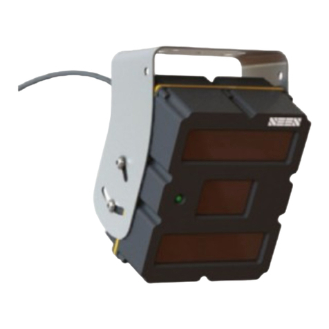
Seen IRIS 860 Sensor Assembly instructions

© Copyright 2020 Seen Safety Limited. All rights reserved. Patents and trademarks granted and pending. Version 1.71 1
Important warning
Please read this guide in full before starting. Incorrect
installation may void the warranty. If you need help
with anything please call the Seen Safety oice on
+64 4 381 4475
Seen IRIS 860 sensors can provide additional
information to the operator but are not intended to
provide active safety functions or control the machine.
Seen sensors do not replace the need for proper
operator training and best practice safe operating
procedure. The operator must always look to check
the way is clear before moving the vehicle. Detection
can never be guaranteed.
Seen sensors and cab boxes require a 12-24V DC
power supply. Voltages exceeding 24V may cause
damage and will not be covered by the warranty.
Caution Class I LASER PRODUCT. Disassembly or
modification of this device may result in hazardous
radiation exposure and will void the warranty.
This installation and set-up guide has been prepared
with all due care and attention, however, Seen Safety
Limited cannot be held responsible for any errors or
omissions in this guide or any consequences thereof.
Contact details
For technical support or questions please contact us.
Seen Safety Limited
Unit 4, 69 Kaiwharawhara Road
Wellington 6035, New Zealand
+64 4 381 4475
www.seensafety.com
info@seensafety.com
Contents
1. Overview 2
2. Mounting bracket 2
3. Sensor location 3
4. Weather shield installation 3
5. Sensor electrical connection 4
6. Cab box electrical connection 5
7. Trouble-shooting the reverse signal input into an
IRIS 860 sensor or cab box 6
8. Cab box sensor cable 7
9. Accessory port and cable 8
10. Sensor config settings 10
11. Self checking function 12
12. Sensor maintenance 12
13. Warranty 12
14. Sensor specifications 13
15. Connector pin-outs and electrical specs. 14
Seen IRIS 860 installation and set-up guide

© Copyright 2020 Seen Safety Limited. All rights reserved. Patents and trademarks granted and pending. Version 1.71 2
1. Overview
Seen IRIS 860 infrared laser sensors have a 60º horizontal x 45º
vertical detection area, and are designed to detect retroreflective
material such as the reflective tape on day/night high visibility
safety vests and markers.
The maximum detection range is 8 metres. The minimum
detection range is 1.2 metres. Detection is indicated by a loud
continuous-tone audible alert.
Sensor settings such as detection distance, volume, direction,
and test mode, can be configured using Seen’s simple PC
configuration app. Refer to Section 10.
IRIS 860 sensors are designed for use on industrial mobile
equipment in indoor and outdoor environments. They can also be
attached to fixed infrastructure to monitor exclusion zones.
2. Mounting bracket
The supplied stainless steel mounting bracket can be attached to
horizontal, vertical, or sloped surfaces. Securely bolt the bracket
to a solid surface using appropriate fasteners.
Once mounted, the sensor should be adjusted in the bracket so it
angles downwards by approximately 27º from horizontal (refer to
the diagrams below).
Tip: In mounting scenarios A and B, the front face of the sensor
should be parallel to the front edge of the bracket as shown by the
dashed lines.
Power or sensor
cable port
Vent
Sensor label
Green LED indicates
power. Red LED indicates
detection
Buzzer
Accessory port
Made in New Zealand
Seen Safety Limited
www.seensafety.com
SN-A00001
CLASS 1 LASER PRODUCT
Complies with FDA performance
standards for laser products except
for conformance with IEC 60825-1
Ed. 3 as described in Laser Notice
No. 56 dated May 8 2019
SEEN IRIS860 Sensor
Input power DC 12-24V 0.7A
Ingress protection IP67
Avoid high pressurewater jets
A. On top
B. Hung
underneath C. Vertical
27º
Correct mounting angle
Sensor front
Sensor back
Mounting bracket
Laser transmit window
LED
Logo
THIS WAY UP
Parallel
Parallel

© Copyright 2020 Seen Safety Limited. All rights reserved. Patents and trademarks granted and pending. Version 1.71 3
3. Sensor location
IRIS 860 sensors should be mounted at head height or higher
with an unobstructed view of the desired detection area. If two
sensors are used to increase the overall detection area, they
can be mounted side-by-side or spaced apart in a cross-over
configuration. Refer to the diagram below.
Detection starts 1.2 m from the sensor face.
B
A
A
A
B
B
A
Detection area (45º)
Detection area (60º)
Side-by-side example Cross-over example
B
A
4. Weather shield installation
• Align the sensor to the correct angle then gently tighten screw
A on both sides.
• Place the weather shield over the bracket, so the round holes fit
around the screw-heads (A) on both sides.
• Insert screw B, check the alignment and evenly tighten all
screws.
Note. It is not possible to attach a weather shield to a sensor
mounted in the ‘hung underneath’ configuration.
B
A
Weather shield

© Copyright 2020 Seen Safety Limited. All rights reserved. Patents and trademarks granted and pending. Version 1.71 4
5. Sensor electrical connection
If the sensor will be connected to a cab box, skip to section 6,
‘Cab box electrical connection’.
The supplied 2 metre power cable has a 5-pin M12 connector at one
end which attaches to the sensor, and bare wires at the other end
for connection to ignition power, ground, and reverse signal.
When powered up the sensor will beep once and the LED will flash
red then glow green. Detections are indicated by a continuous alert
tone and red LED.
Note: To minimise irrelevant detections, a connection to the reverse
signal allows sensors set to ‘R’ (reverse) to alert only while the
machine is reversing. A forward facing sensor can be set to ‘F’ and will
only alert when the machine is not reversing. Refer to section 10 for
more information about the config settings.
Note: If the BROWN (ignition) and BLACK (reverse) wires are twisted
together so they both receive 12-24V ignition power, an ‘R’ set sensor
will alert in any context.
TROUBLE SHOOTING. If an ‘R’ set sensor appears correctly
powered and connected to the reverse circuit but does not detect
as expected, please refer to section 7: Trouble-shooting the
reverse signal input into an IRIS 860 sensor or cab box.
Sensor power
cable
BLUE
Ground
Reverse (centre)
Ignition power
Orientation slot
Ground
Sensor power cable
BROWN
Input power (ignition)
DC 12-24V 0.7A
BLACK
Reverse signal
DC 12-100V 1mA

© Copyright 2020 Seen Safety Limited. All rights reserved. Patents and trademarks granted and pending. Version 1.71 5
6. Cab box electrical connection
Seen’s cab box provides an audible detection alert and LED
indication to the driver inside the cab. Up to four sensors can be
connected to a cab box.
The cab box is powered by a 4-pin M12 power cable (supplied)
which is wired to the machine’s ignition power, ground, and
reverse signal (optional).
Note: To minimise irrelevant detections, a connection to the reverse
signal allows sensors set to ‘R’ (reverse) to alert only while the
machine is reversing. A forward facing sensor can be set to ‘F’ and
will only alert when the machine is not reversing. Refer to section 10
for more information about the config settings.
TROUBLE SHOOTING. If an ‘R’ set sensor attached to the cab
box appears correctly powered but does not detect as expected,
please refer to section 7: Trouble-shooting the reverse signal
input into an IRIS 860 sensor or cab box.
Cab box power cable
Cab box
Sensor cable
connectors
LED
Buzzer
BLUE
Ground
Ignition power
Orientation slot
Ground
Reverse
Cab box power cable
BROWN
Input power (ignition)
DC 12-24V 2.8A
BLACK
Reverse signal
DC 12-100V 1mA

© Copyright 2020 Seen Safety Limited. All rights reserved. Patents and trademarks granted and pending. Version 1.71 6
7. Trouble-shooting the reverse
signal input into an IRIS 860 sensor
or cab box
Applies to: Sensors requiring a reverse signal input to indicate
when to alert. Cab boxes connected to the reverse signal.
Problem: The sensor / cab box appears correctly powered and
connected to the reverse signal, but the sensor does not alert
when the vehicle is in reverse.
Cause: The sensor’s reverse signal detection circuit is not
registering the reverse signal input. This is most likely caused by
a grounding issue.
How to check the reverse signal
• Unplug the sensor / cab box from its power cable
• Switch the vehicle ignition to ON (preferably without starting
the vehicle for safety)
• Attach a voltmeter across the Ignition power pin (+) and the
Ground pin (–) of the power cable. The voltage should be
between +10V and +30V. Refer to the Sensor / Cab box power
cable diagram (opposite)
• Next, attach the voltmeter across the Reverse pin and the
Ground pin (–). When the vehicle is NOT in reverse the voltage
should measure between 0V and +1V. When the vehicle IS in
reverse it should measure between +3V to +100V.
If the vehicle is in reverse and the voltage is not 3-100V between
the Ground pin (–) and the Reverse pin, there may be a grounding
issue.
DC/DC converter grounding issue
Some installations (typically electric machines) require a DC/DC
converter to reduce the supply voltage to 12 or 24V. If the DC/
DC converter is an isolated type, the ground reference for the
sensor’s power supply can be dierent from the ground reference
for the reverse circuit.
The DC/DC converter circuit diagram (opposite) will not work
because the reverse signal input is isolated from the IRIS 860
sensor ground (-Vin on the IRIS 860 sensor)
Making a connection across the DC/DC converter isolation barrier
(shown as the dashed ‘jumper’ line) means all the circuits now
have a common ground. HOWEVER this is not advisable if other
accessories also use the DC/DC converter because the isolation
barrier may be required for safety. In this case the best solution is
to use a separate DC/DC converter for the IRIS 860 sensor with
the jumper line connected as shown.
Note. To check if an ‘R’ set sensor is working correctly, supply 12-
24V to both the ignition wire (brown) and reverse wire (black). A
properly functioning sensor wired in this way will always be active
and trigger o a reflective vest. (Note the 1.2m minimum operating
range when testing).
Isolated DC/DC
converter
High voltage
DC supply
Reverse
signal
Chassis
ground
IRIS 860 Sensor
Other accessory
+Vin
+30V to
+100V
+3V to +100V
+24V
+Vout
+Vin
+Vin
–Vin
–Vout
–Vin
–Vin
Reverse in
Jumper line
Sensor / Cab box power cable
Reverse (Sensor
power cable)
Reverse (Cab Box
power cable)
Ignition power (+)
Orientation slot
Ground (–)
DC/DC converter circuit

© Copyright 2020 Seen Safety Limited. All rights reserved. Patents and trademarks granted and pending. Version 1.71 7
5. Grey (Centre)
4. Black
Screw-block
3. Blue2. White
1. Brown
Re-wireable connector
9mm16mm
Cable
Wire stripping guide
Grey wire (centre)
Other wires
8mm 9mm
8. Cab box sensor cable
A cab box sensor cable is required to connect each sensor to the
cab box. This cable supplies power to the sensor, and transmits
the detection signal back to the cab box.
To facilitate cable threading, or to shorten the cable, the larger
black plastic connector can be removed and re-wired.
IMPORTANT
When re-wiring the connector, the wire colours must exactly
match the diagram opposite. Use the screw-block as a reference.
Unscrew first
Unscrew second
Re-wireable connector

© Copyright 2020 Seen Safety Limited. All rights reserved. Patents and trademarks granted and pending. Version 1.71 8
9. Accessory port and cable
The IRIS 860 sensor features an 8-pin M12 accessory port. Seen’s
accessory cable can be used to attach and trigger third-party
accessories such as cameras, data-loggers, alarms etc.
Pin no. Wire colour Description
1 Brown 12V accessory power supply
2 White Ground / Earth
3 Blue Detection NPN
4 Black Detection 3V6 logic output
5Grey Do not connect
6 Pink Detection 12V logic output
Accessory use-case examples
12V external buzzer or light
IRIS 860 sensor
12V accessory
GND
NPN switch
connects to ground
during detection
1
2
3
4
5
6
7
8
12V power supply (BROWN)
IRIS 860 ground (WHITE)
Detection NPN (BLUE)
Detection 3V6 (BLACK)
Do not connect (GREY)
Detection 12V (PINK)
–
+
Accessory port / cable
• On detection the NPN transistor switch closes, putting 12V
across the connected accessory
• Maximum supply current 500mA.
12V external relay
IRIS 860 sensor
12V relay
GND
NPN switch
connects to ground
during detection
1
2
3
4
5
6
7
8
12V power supply (BROWN)
IRIS 860 ground (WHITE)
Detection NPN (BLUE)
Detection 3V6 (BLACK)
Do not connect (GREY)
Detection 12V (PINK)
–
+
Accessory port / cable
• On detection, the NPN transistor switch closes, putting 12V
across the relay
• A flywheel diode is required across the relay coil to protect the
NPN transistor against the coil transient when the detection
event ends and the coil is switched o
• Maximum supply current 500mA.
Accessory port
Made in New Zealand
Seen Safety Limited
www.seensafety.com
SN-A00001
CLASS 1 LASER PRODUCT
Complies with FDA performance
standards for laser products except
for conformance with IEC 60825-1
Ed. 3 as described in Laser Notice
No. 56 dated May 8 2019
SEEN IRIS860 Sensor
Input power DC 12-24V 0.7A
Ingress protection IP67
Avoid high pressurewater jets
Flywheel diode

© Copyright 2020 Seen Safety Limited. All rights reserved. Patents and trademarks granted and pending. Version 1.71 9
12V camera with digital input
IRIS 860 sensor
GND
1
2
3
4
5
6
7
8
12V power supply (BROWN)
IRIS 860 ground (WHITE)
Detection NPN (BLUE)
Detection 3V6 (BLACK)
Do not connect (GREY)
Detection 12V (PINK)
12V camera accessory
Output high during detection
12V trigger input
–
+
12V power supply
Accessory port / cable
• The IRIS 860 accessory power supply is used to power the camera
accessory (maximum supply current 500mA)
• Detection 12V puts 12V on the camera trigger during detection (this is a
low power output and can only sink/source a few milliamps of current).
• If required, add an external regulator to limit the 12V detection logic
output voltage (e.g. down to 5V or 3.3V) or use Detection 3V6 (black) for a
3.6V detection output.
Also refer to section 15 for the Accessory Port PIN-out diagram for full
electrical specifications.

© Copyright 2020 Seen Safety Limited. All rights reserved. Patents and trademarks granted and pending. Version 1.71 10
10. Sensor config settings
IRIS 860 sensors are supplied with a default setting which is
indicated on the config sticker on the back of each sensor.
These settings can changed using a simple PC desktop software
application which can be downloaded for free at
www.seensafety.com/download
An IRIS 860 USB config cable is needed to connect the sensor’s
power port to the computer’s USB port.
Instructions
• Launch the IRIS 860 software app (Windows PC required)
• Connect the config cable USB plug directly to the computer
USB port, THEN connect it to the sensor power port
• The sensor will power up (indicated by green LED). Wait a few
seconds for the sensor to boot (indicated by a brief change to
red LED) and once booted, click “Connect”
• Update the settings then click “Apply New Settings”
• Check the new settings are correct, then unplug the sensor and
repeat for the next sensor.
TROUBLE SHOOTING.
• Make sure the sensor finishes booting (red LED followed by
steady green LED) before clicking “Connect”.
• If the sensor is powered on (green LED) but fails to connect,
try installing the Windows drivers included with the software.
Range setting
The detection range can be set in 0.5 metre steps up to 8.0
metres. Select Custom Range to individually change the range of
each channel (see examples on the following page).
Direction setting
A Reverse (R) set sensor will only alert in the presence of a 12-
100v reverse signal from the machine. A Forward (F) set sensor
will only alert when a reverse signal is not present. An Always
(A) set sensor will alert even if it is connected to a reverse signal
input.
Test Mode setting
A Test Mode enabled sensor can be temporarily toggled to test
mode using a simple ignition on-o-on sequence. When test mode
is active, the reverse direction (R) setting is ignored for 2 minutes.
This allows an operator to walk behind the machine to test the
sensor/s function without the machine needing to be in reverse
gear.
Test procedure:
• Turn the ignition on (to power the sensor), wait 2 to 5 seconds,
then turn the ignition o. The next time the ignition is turned
on the sensor will be in test mode indicated by a flashing green
LED on the sensor and cab-box (if used).
• Test mode lasts 2 minutes. The green LED on the sensor and
cab box (if used) flashes during this period indicating test mode
is active.
• Check the sensors are working by walking into the detection
zone behind the machine wearing a reflective safety vest.
Detection is indicated by an audible alarm and red LED.
Custom Range
Sensor config sticker, indicating the sensor is
set to 4 metres, reverse mode.
Power port
Made in New Zealand
Seen Safety Limited
www.seensafety.com
SN-A00001
CLASS 1 LASER PRODUCT
Complies with FDA performance
standards for laser products except
for conformance with IEC 60825-1
Ed. 3 as described in Laser Notice
No. 56 dated May 8 2019
SEEN IRIS860 Sensor
Input power DC 12-24V 0.7A
Ingress protection IP67
Avoid high pressurewater jets
Sensor config. application
Sensor connected
Custom range setting panel*

© Copyright 2020 Seen Safety Limited. All rights reserved. Patents and trademarks granted and pending. Version 1.71 11
• Return to the cab and engage reverse gear to test the reverse
signal. The audible alarm should sound when the reverse signal
is detected.
• The test is now complete. Turn the ignition o, restart the
vehicle and operate as normal.
• To clear test mode at any time simply switch the ignition o,
then re-start the machine.
Sensitivity setting
Reduced sensitivity mode may help in environments where
false detections are occurring. False detections are defined as
detections which do not come from a retroreflector. Although
uncommon, the sensor may occasionally be triggered by plastic
stretch-wrap in certain conditions, and from certain metallic
surfaces which create a retroreflective type eect. Low sensitivity
mode slightly increases the amount of retro-reflective tape
required to enable detection, and may prevent some false
detections.
Volume reduction
This setting reduces the alert tone from very loud to loud. It can
be used in situations where the sensor is close to the operator
and the alert tone is uncomfortably loud. The 3.5kHz alert tone is
94dB at 1 metre.
Default detection area
Custom detection
area examples
Two sensors with mirrored
custom shaped detection area

© Copyright 2020 Seen Safety Limited. All rights reserved. Patents and trademarks granted and pending. Version 1.71 12
SI860-1119
SN-A01000
11. Self checking function
IRIS 860 sensors have an automatic self checking function that
can alert the operator of an internal fault, or if the laser transmit
window becomes excessively contaminated and needs cleaning.
If the sensor LED (and cab box if used) repeatedly flashes red
and beeps, the sensor is indicating a fault. Stop the machine.
Try cleaning the sensor windows (see below) but if this does not
correct the issue, please contact your Reseller/Supplier or Seen
Safety to arrange repair or replacement.
12. Sensor maintenance
There are no user-serviceable parts in the sensor. Other than
keeping the windows and buzzer free from dust and dirt build-
up, no scheduled maintenance is required. Remove dust and dirt
using clean water and a clean non-abrasive cloth. The sensor and
buzzer are rated IP67 (protected from dust ingress and water
ingress at 1 metre submersion for 30 minutes). Do not use high
pressure water jets to clean.
13. Warranty
Seen IRIS 860 sensors have been designed for reliable long-term
use on industrial vehicles in both indoor and outdoor applications.
Seen oer a 1-year repair or replacement warranty on materials
and workmanship. The warranty excludes general wear and tear,
physical damage caused by direct impact to the sensor, damage
to the windows, damage caused by high-pressure water jets, or
incorrect electrical connection. There are no user serviceable
parts. Opening the sensor will void the warranty.
Sensor label

© Copyright 2020 Seen Safety Limited. All rights reserved. Patents and trademarks granted and pending. Version 1.71 13
14. Sensor specifications
Input power (ignition) DC 12-24 V 0.7A
Reverse signal input DC 3.5-100V 1mA
Power consumption 1.5W max (sensor only)
8.4W max (with attached accessories)
Detection range 1.2 - 8.0 metres
Detection area 60 degrees horizontal x 45 degrees vertical
Detection target Class II day/night high visibility safety
apparel / vest and other retroreflective
material
Latency Up to 250ms
Maintenance No scheduled maintenance required
Buzzer 94dB at 1m 3500Hz
Connectors M12 5-pin and M12 8-pin auxiliary port
Laser type Pulsed infrared 905nm non-visible
Safety Caution Class I LASER PRODUCT.
Disassembly or modification of this device
may result in hazardous radiation exposure.
Standards IEC 61000-6-4 (EMC emissions)
IEC 61000-4-2 (EMC immunity)
IEC 60825-1:2014 (Laser eye safety)
IEC 61010-2-201:2017 (Electrical equipment
safety)
Lighting Immune from sunlight interference or
ambient lighting conditions.
Ingress protection IP67. Protected from dust ingress and
water ingress at 1 metre submersion for 30
minutes. Avoid high pressure water jets
Enclosure ASA injection moulded plastic
Mounting 4 x M6 brass inserts
Windows Hard coated IR filtered PMMA
Weight 0.48 kg
Dimensions 125W x 160H x 85D
Operating temperature: -20 to +60 degrees C ambient
Product specifications are subject to change without notice to improve reliability, function, design or
otherwise.

© Copyright 2020 Seen Safety Limited. All rights reserved. Patents and trademarks granted and pending. Version 1.71 14
15. Connector pin-outs and electrical specs.
Power connector (M12 5-PIN)
5
4
1 2
3
Pin Name Description Direction Max.
input
voltage
Min.
input
voltage
Input
high
voltage
Input
low
voltage
Output
high
voltage
Output
low
voltage
Conditions Notes
1 Vin + Supply positive Input 30v 10.8v - - - - - 8W maximum power
draw (with attached
accessory). 2W maxi-
mum for sensor only.
2 Vin – Supply nega-
tive (ground)
- - - - - - - - System / chassis
ground
3 System
status
High when sys-
tem operating
Output - - - - 5.2v max.
4.5v min.
0.1v max. 1K Ohm load
to ground
PNP output
4 Detection High when tar-
get detected
Output - - - - 5.2v max.
4.5v min.
0.1v max. 1K Ohm load
to ground
PNP output
5 Reverse in Reverse input Input 100v 0v 3.5v min. 1v max. - - - Input current is less
than 0.5 mA
Accessory connector (M12 8-PIN)
6
12
3
4
5
Pin Name Description Direction Max.
input
voltage
Min.
input
voltage
Input
high
voltage
Input
low
voltage
Output
high
voltage
Output
low
voltage
Conditions Notes
1 12V out Accessory supply Output - - - - 12.1v max.
10v min.
- Supply
voltage 12v
and drawing
500mA from
accessory
supply pin
Accessory supply,
eg external alert or
camera
2 Vin – Supply negative
(ground)
- - - - - - - - System / chassis
ground
3 Detection
NPN
Detection output Output - - - - 30v max. 0.8v
max.
0.8v output
low max when
sinking 500
mA
NPN output, max
blocking voltage
30v
4 Detection
3V6
Low voltage logic
detection output
Output - - - - 3.6v max.
2.0v min.
- Source / sink
100 uA max.
-
5 Do not connect
6 Detection
12V
High voltage logic
detection output
Output - - - - 11v max.
9.3v min.
- Supply
voltage 12v,
2K Ohm load
to ground
-
Other manuals for IRIS 860 Sensor
3
Table of contents
Other Seen Accessories manuals
Popular Accessories manuals by other brands
B.E.G. LUXOMAT
B.E.G. LUXOMAT PD1-M-2C Installation and operating instruction manual
PCB Piezotronics
PCB Piezotronics 117B67 Installation and operating manual
Crown
Crown PIP-FTE reference guide
Powerfix Profi
Powerfix Profi 292045 Operation and safety notes
SICK
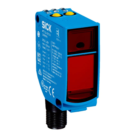
SICK PowerProx WTT12L-A Series operating instructions

Peavey
Peavey Model 22T user guide
