PowerBox Systems POWERBUS 9200 User manual

Instruction Manual
PowErBus

2PowerBox-Systems − World Leaders in RC Power Supply Systems
Dear customer,
We are delighted that you have decided to purchase this PowerBox accessory from
our range.
We hope you have many hours of pleasure and great success with your PowerBUS
devices.
The PowerBUS is the basis of a completely new method of wiring servos. The
PowerBUS consists of a three-core cable which supplies current and signal to the
servos connected to it. At rst glance this is nothing unusual, but the big difference
lies in the signal wire. When conventional servo signals are transferred, the signal
wire always carries the information for one individual servo only - this is a PWM
(Pulse Width Modulated) signal. In a servo bus system the signal wire carries posi-
tional information for multiple servos in digital form. The information for individual
servos includes address data, and since each servo is assigned its own individual
address, it can read out „its“ information from the data stream, and convert it into a
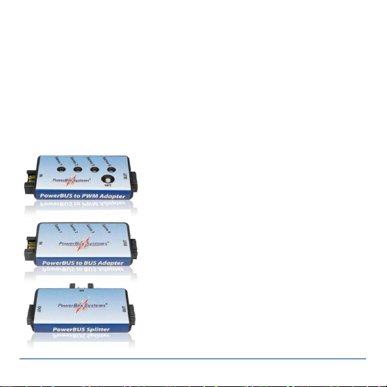
movement of the control surface. PowerBus to PWM adapters can also be emplo-
yed to enable the use of servos without their own decoder; in this case the adapter
carries out the decoding.
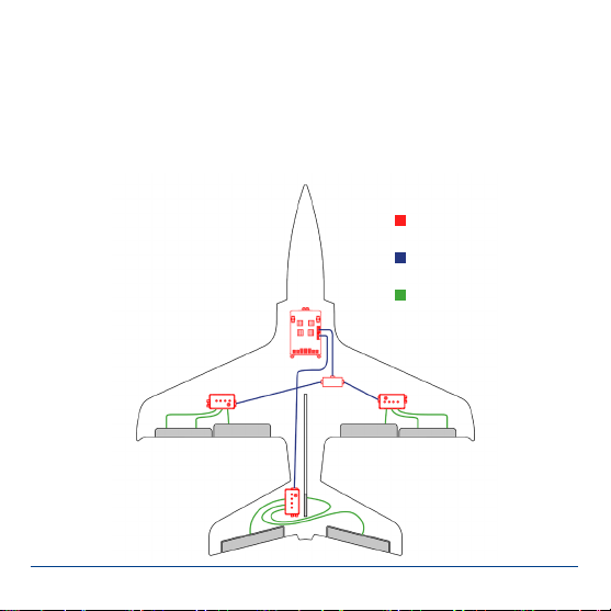
The advantage of this arrangement is obvious: all you need is one three-core lead
in order to supply the essential information to several servos. The wiring is much
simpler, and there is also a signicant weight saving.
However, until now there has always been one disadvantage to bus systems: a
short-circuit in one servo causes the bus lead to be blocked, and all the servos
connected to it stop working. Here at PowerBox-Systems we have completely eli-
minated this former drawback:
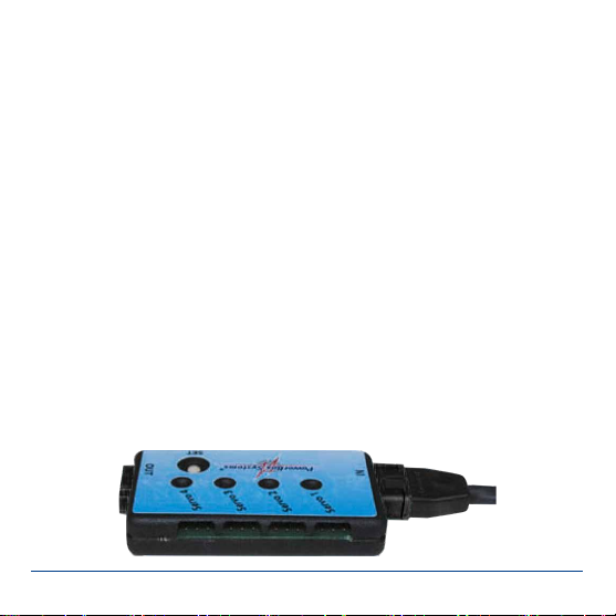
The servo distributors which we have developed are protected against short-cir-
cuits in the power supply lines and the signal line! This means that, if one output is

www.powerbox-systems.com 3
shorted out at a servo distributor, within a few micro-seconds that output is swit-
ched off, and the bus lead remains active.
This supplementary feature is very important to ight safety, since a servo bus
without it can never be suitable for use in valuable model aircraft!
The following section introduces and describes the individual components of the
PowerBUS:
1. OVERVIEW OF POWERBUS COMPONENTS
Three different types of distributor are available:
Order No. 9200 - PowerBUS to PWM Adapter
Quadruple distributor with integral BUS/PWM con-
verter
Order No. 9210 - PowerBUS to BUS Adapter
Quadruple distributor for bus-enabled servos
Order No. 9220 - PowerBUS Splitter
Splitter, for converting one PowerBUS lead into
two

4PowerBox-Systems − World Leaders in RC Power Supply Systems
The following standard cable lengths are available:
Order No. 9126/30
PowerBUS connecting lead, MPX plug / MPX socket, length 30 cm
Order No. 9126/60
PowerBUS connecting lead, MPX plug / MPX socket, length 60 cm
Order No. 9126/90
PowerBUS connecting lead, MPX plug / MPX socket, length 90 cm
Order No. 9126/120
PowerBUS connecting lead, MPX plug / MPX socket, length 120 cm
We can also make up PowerBUS connecting leads to the exact lengths you require.
Please refer to our webshop, where you will nd a conguring tool for this purpose.

www.powerbox-systems.com 5
2. DESCRIPTION OF POWERBUS COMPONENTS
a) PowerBUS Splitter
The PowerBUS Splitter is required if the PowerBox does not feature a sufcient
number of outputs. For example, if you wish to use the bus technology for both
wings as weil as elevator and rudder, you will need a total of three bus leads. The
following diagram shows a typical PowerBUS installation:
PowerBUS Components
PowerBUS Wires
Servo Wires

6PowerBox-Systems − World Leaders in RC Power Supply Systems
b) PowerBUS to BUS Adapter
The PowerBox to BUS Adapter is designed for use with servos which are tted
with an integral bus decoder. At present these are Futaba S-Bus servos. When the-
se servos are used, the channel assignment is programmed directly at the servo.
The PowerBox to BUS Adapter does not feature a decoder, but nevertheless all the
outputs are protected against short-circuits both in the signal wire and the power
supply wires, as you would expect. The adapter includes integral signal ampliers
for all servo outputs as weil as the adapter's PowerBUS output. This means that as
many bus adapters as required can be connected in series, i.e. cascaded.
c) PowerBUS to PWM Adapter
The PowerBox to PWM Adapter is used for servos which are not lled with a bus
decoder. In this case the channel assignment is dened at the PowerBUS to BUS
Adapter. The bus signal is decoded in the adapter, which then generates conventi-
onal PWM signals for the servos. This unit allows all known makes of servo to be
operated with the PowerBUS system. As with the other adapters, all the outputs
are protected against short-circuits both in the signal wire and the power supply
wires. The adapter includes integral signal ampliers for all servo outputs as well
as the adapter's PowerBUS output. This means that as many bus adapters as re-
quired can be connected in series, i.e. cascaded.

www.powerbox-systems.com 7
3. THE POWERBUS - BASIC INFORMATION
The PowerBUS can carry 16 channels + 2 switched channels. lt is possible to as-
sign any functions you wish to the bus, thanks to the unrestricted channel assign-
ment facilities of the Champion SRS and Royal SRS. This is important: for examp-
le, if you wish to assign the aileron signal - as it comes from the transmitter - to the
PowerBUS, and also wish to include the gyro gain and servo match settings. The
door sequencer function can also be assigned to the PowerBUS.
a) Procedure for setting up the PowerBox
Requirement for subsequent steps:
The type of radio control system must be entered correctly at the PowerBox.
lf you are using a gyro (with the Royal SRS), you must rst complete the iGyro As-
sistant procedure to complete the channel assignment on the input side.
The rst step in assigning particular outputs to the bus is to assign the function in
the Output Mapping menu of the PowerBox:

8PowerBox-Systems − World Leaders in RC Power Supply Systems
You will nd this standard display in the OUTPUT MAPPING menu of the Royal
SRS. Functions can only be assigned to the PowerBUS if they have already been
dened under OUTPUT MAPPING.
These instructions include an example which shows the step-by-step procedure for
assigning the bus; it also shows how to use the ServoMatch function in conjunction
with the PowerBUS.
The function of output Gis GYRO AILERON A, and the function of output His also
GYRO AILERON A. At rst sight the function of both outputs is the same. However,
these two functions are to be assigned to an aileron actuated by two servos. The
ServoMatch function is used for ne-tuning, to ensure that the travel of both servos
is identical.
Note: in the case of the Champion SRS it is only possible to select the DIRECT 1 -
16 and DS1 - 6 outputs instead of the gyro channels.
Once the function assignment process is complete, move the cursor to the left
to P-BUS and conrm your choice by pressing the SET button. You will see this
display:

www.powerbox-systems.com 9
The column under P-BUS indicates the PowerBUS channel number. CH1 - CH16
are proportional channels, while CH17 and CH18 are switched channels. At a later
stage these numbers are crucial when we move on to programming the servo or
the PowerBUS adapter.
The OUTPUT is user-variable; here you determine which PowerBox output (A - X)
is assigned to the selected BUS channel (1 - 18).
The FUNCTION column shows which function is assigned to the output you have
selected. This provides a clear overview of the functions which are already assi-
gned to the bus.
In our example the gyro function GY AILERON A has been assigned to outputs G
and H, so that these two functions can be ne-tuned later using the ServoMatch
function. At the PowerBUS they have been assigned to channel numbers 2and 3.
b) Procedure for setting up the PWM Adapter
Our function GY AILERON A is now assigned to bus channels 2 and 3. The next
stage must be to inform the PowerBUS to PWM Adapter (description under 2c)
which bus channel is to be generated at which of the four sockets (servo 1 - 4).

10 PowerBox-Systems − World Leaders in RC Power Supply Systems
This is the procedure:
b1) Do not connect the adapter to the PowerBUS lead at this stage.
b2) Connect the PowerBUS lead to the PowerBox.
b3) Press the SET button on the adapter while you plug in the PowerBUS lead.
b4) The red LED lights up at servo 1, then moves step-by-step to servo 4 while you
hold the button pressed in.
b5) Release the button when the red light is aligned with the servo output which
you want to set up. The red LED now shines less strongly.
b6) To program the output: Briey press the button the same number of times as
the channel which you wish to set up. Tor example, press the button ve times
in sequence for channel 5.
b7) When you have nished programming one output, save the setting simply by
disconnecting the adapter from the PowerBUS lead. Resume at Point b2) to
assign a further output.
Back to our example with two ailerons:
Hold the SET button pressed in while you connect the bus adapter, then immedia-
tely release it again. Servo output 1 at the adapter is required to generate PowerBox
output G: press the SET button twice in order to assign bus channel 2 to servo
output 1. Now disconnect the bus adapter again.

www.powerbox-systems.com 11
Hold the SET button pressed in once more while you connect the bus adapter, but
this time wait until the LED moves on to servo output 2. Servo output 2 at the adap-
ter is required to generate PowerBox output H: press the SET button three times in
order to assign bus channel 3 to servo output 2. Disconnect the bus adapter again.
Now connect the bus adapter and the two servos (outputs 1 and 2), and move the
aileron stick at the transmitter: the two servos should operate in parallel.
At this point you should call up the ServoMatch function at the PowerBox to ensure
that the two aileron servos do not work against each other mechanically.
First select output H, and ne-tune the servo which is connected to servo output
2 at the PowerBUS adapter to match the movement of the rst servo. Refer to the
instructions supplied with the Royal / Champion SRS for a detailed description of
this procedure.

12 PowerBox-Systems − World Leaders in RC Power Supply Systems
4. POWERBUS CABLE
PowerBUS cable is manufactured specially for PowerBox-Systems. The Power-
BUS cable is extremely exible, and is made up using very thin individual strands
in order to pass the maximum current through the given cross-sectional area of
1.5mm2. The insulation is made of a special material which is also employed in
full-size aviation. lt is virtually indestructible, and offers excellent protection even
when reduced to just a thin lm around the copper conductor. This insulation pro-
duces a weight reduction of about 30% compared with the much cheaper PVC.
The insulation is not inammable, and its heat resistance is much higher than the
usual PVC.
To save more weight, the conductors are of different thickness: power is carried by
two thick wires (1.5mm2), while a thin wire of 0.25mm2is used for the signal. This
produces a further weight saving of 27%.
The picture clearly shows the thin insulation, the ne individual strands, and the
difference in cross-sectional area between the power and signal wires.

www.powerbox-systems.com 13
5. PIN ASSIGNMENT
One great advantage of the PowerBUS is that it employs standard commercial
MPX connectors. We supply PowerBUS leads in standard lengths, but can also
make them up to the lengths you need. Please note that some installations present
problems, with the result that the connectors can only be attached once the lead
has been installed.
The following photos show the correct pin assignments:
Caution: PowerBUS adapters are protected from reverse polarity, but if you
plug servos into an incorrectly wired PowerBUS, they will instantly be ruined!
For this reason it is essential to observe correct polarity, and compare your
soldered connectors with the photos shown above!
PowerBUS socket PowerBUS plug
3x GND
2x PWR
1x SIGNAL

14 PowerBox-Systems − World Leaders in RC Power Supply Systems
6. SERVICE NOTE
We make every effort to provide a good service to our customers, and have now
established a Support Forum which covers all queries relating to our products. This
helps us considerably, as we no longer have to answer frequently asked questions
again and again. At the same time it gives you the opportunity to obtain assistance
all round the clock, and even at weekends. The answers come from the PowerBox
team, which guarantees that the answers are correct.
Please use the Support Forum before you contact us by telephone.
You will nd the forum at the following address:
www.forum.powerbox-systems.com
7. GUARANTEE CONDITIONS
At PowerBox-Systems we insist on the highest possible quality standards in the
development and manufacture of our products. They are guaranteed “Made in
Germany”!
That is why we are able to grant a 24 month guarantee on the PowerBox acces-
sory from the initial date of purchase. The guarantee covers proven material faults,
which will be corrected by us at no charge to you. As a precautionary measure, we
are obliged to point out that we reserve the right to replace the unit if we deem the
repair to be economically unviable.
Repairs which our Service department carries out for you do not extend the original
guarantee period.

www.powerbox-systems.com 15
The guarantee does not cover damage caused by incorrect usage, e.g. reverse
polarity, excessive vibration, excessive voltage, damp, fuel, and short-circuits. The
same applies to defects due to severe wear.
We accept no liability for transit damage or
loss of your shipment. If you wish to make a
claim under guarantee, please send the device
to the following address, together with proof of
purchase and a description of the defect:
8. LIABILITY EXCLUSION
We are not in a position to ensure that you observe our instructions regarding in-
stallation of the PowerBox accessory, full the recommended conditions when
using the unit, or maintain the entire radio control system competently.
For this reason we deny liability for loss, damage or costs which arise due to the
use or operation of the PowerBox accessory, or which are connected with such
use in any way. Regardless of the legal arguments employed, our obligation to pay
damages is limited to the invoice total of our products which were involved in the
event, insofar as this is deemed legally permissible.
We wish you every success using your new PowerBUS!
Donauwoerth, December 2020
SERVICE ADDRESS
PowerBox-Systems GmbH
Ludwig-Auer-Straße 5
D-86609 Donauwoerth
Germany

PowerBox-Systems GmbH
Ludwig-Auer-Straße 5
D-86609 Donauwoerth
Germany
+49-906-99 99 9-200
+49-906-99 99 9-209
www.powerbox-systems.com
12/2020
This manual suits for next models
2
Table of contents
Other PowerBox Systems Media Converter manuals