4 Function
4.1 Overcurrent protection
¡Over Current Protection (OCP) is built-in and works at 105% of
the rated current or higher. However, use in an overcurrent situa-
tion must be avoided whenever possible.
The output voltage of the power module will recover automatically
when the fault causing overcurrent is corrected.
When the output voltage drops after OCP works, the power mod-
ule enters a ”hiccup mode” where it repeatedly turns on and off at
a certain frequency.
4.2 Thermal protection
¡When the power supply temperature is kept above 120C, the
thermal protection will be activated and simultaneously shut down
the output.
The output voltage of the power supply will recover automatically
when the unit is cool down.
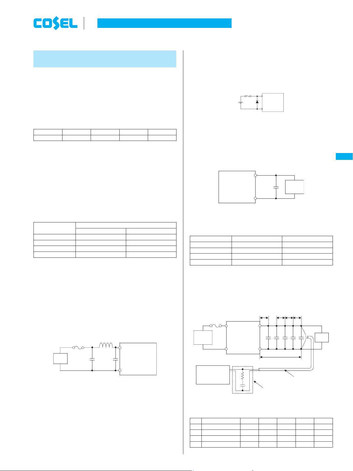
4.3 Remote ON/OFF
¡The remote ON/OFF function is incorporated in the input circuit
and operated with RC and GND. If positive logic control is re-
quired, order the power supply with “-R” option.
Table4.1 Specification of Remote ON/OFF
ON/OFF
logic Between RC and GND Output
voltage
Standard Negative L level(-0.2 - 0.6V) or short ON
H level(3.0 - VIN) or open OFF
Optional -R Positive L level(-0.2 - 0.6V) or short OFF
H level(3.0 - VIN) or open ON
*Source current from RC pin is 0.5mA(max).
¡When remote on/off function is not used, please short GND and
RC.
SW
RC
RC
RC
GND
GND
Transistor
External
Power supply
(a ()b)
(c ()d)
GND
VCC
( Vin)
IC
DC
input DC
input
+VIN
RC
GND
+VIN
Fig.4.1 RC connection example
4.4 Remote sensing
(1) When the remote sensing function is not in use
+S
+VOUT
-
S
GND
LOAD
Short at pin root
Fig.4.2 Connection when the remort sensing is not in use
¡When the remote sensing function is not in use, it is necessary to
confirm that pins are shorted between +S & +VOUT and between
-S & GND.
¡Wire between +S & +VOUT and between -S & GND as short as
possible.
Loop wiring should be avoided.
This power supply might become unstable by the noise coming
from poor wiring.
(2) When the remote sensing function is in use
GND
+S Load
-S
+VOUT
Wire as close as possible
Fig.4.3 Connection when the remote sensing is in use
¡Twisted-pair wire or shield wire should be used for sensing wire.
¡Thick wire should be used for wiring between the power supply
and a load.
Line drop should be less than 0.5V.
Voltage between +VOUT and GND should remain within the out-
put voltage adjustment range.
¡If the sensing patterns are short, heavy-current is drawn and the
pattern may be damaged.
The pattern disconnection can be prevented by installing the pro-
tection parts as close as a load.
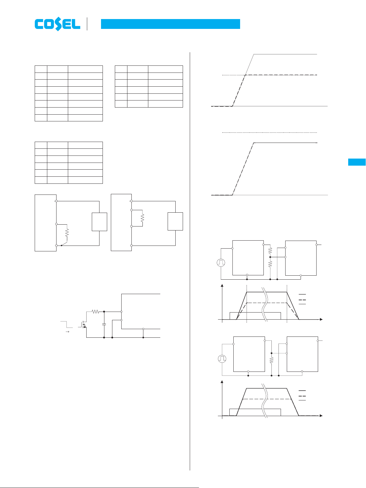
4.5 Adjustable voltage range
¡Output voltage is adjustable by the external resistor.
¡The temperature cofficiect could become worse, depending on the
type of a resistor.
Resistor.....Metal film type, coefficient of less than ±100ppm/C
¡When TRM is opened, output voltage is adjusted to the minimum.
¡RTRM is calculated in the following expressions.
BRFS30 BRFS40 BRFS50/50L/60/100
RTRM =[kW]
8
VOUT㧙0.8
RTRM =[kW]
12
VOUT㧙0.6
RTRM =[kW]
14
VOUT㧙0.7
DC-DC Converters PCB Mount type Instruction Manual
BRFS-10
BRFS