Hardwire to the vehicle fuse box
Hardwiring a dashcam to the vehicle’s fuse box is one of the most common installation methods to power on
your dashcam. In order to utilize the V-AI12 full features such as active standby, the camera must be
connected to a constant 12V power source.
NOTE: The hardwiring kit includes 2 wires; one RED wire that connects to a constant 12V source and a BLK
ground wire that will go to a metal ground bolt.
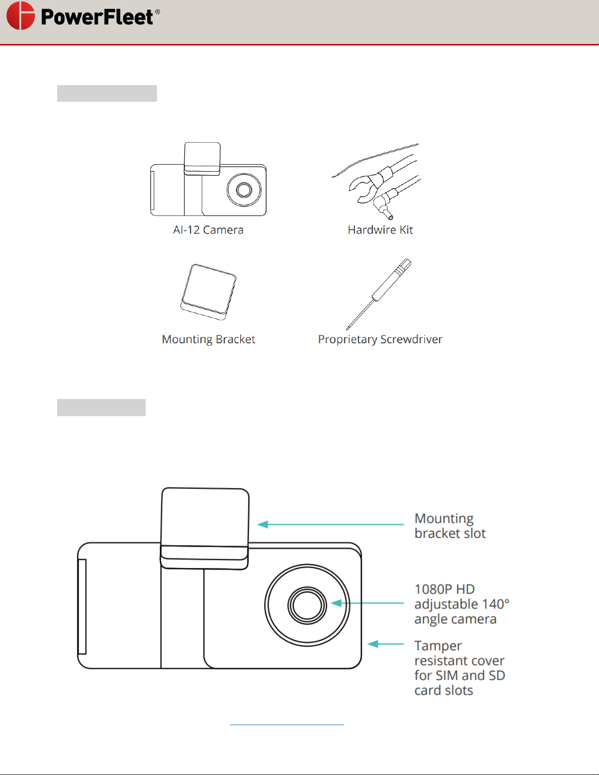
Essential Install Package
WARNING: This type of installation should only be performed by a qualified technician. Working with your
vehicle’s power system can be dangerous for you and your vehicle. If you have any concerns, consult a
professional.
Hardwire to the vehicle fuse box
STEP 1: LOCATE YOUR FUSE BOX
Check the car owner’s manual for the fuse box location. It may vary depending on the vehicle model. Remove
the plastic panel to access the fuse box. It may open simply by lifting a tab, pulling it with your fingers, or using
a flat tool to insert and separate the cover.
STEP 2: WHICH SLOT SHOULD I USE?
Use a circuit tester to test which fuse is constant (typically red) and provides 12V of power. A fuse that is
constant will stay active when the car is off. The camera will automatically enter standby mode when the car
has not moved for 10 minutes.
STEP 3: INSTRUCTIONS TO ADD-A-FUSE KIT
We recommend using the add-a-fuse kit included in our Essential Install
Package, for a more secure, long lasting installation. The add-a-fuse kit
provides a fuse slot for the existing OEM circuit (constant or ignition
switched, #2 in picture right) and another fuse slot for the new circuit for
the dashcam device (#1 in picture right).