BrandMotion 9002-8848 User manual

8848 Instructions 12-18-14.docx Page 1 of 5
Jeep Wrangler Adjustable Rear Vision Camera, 2007 – Current
(Kit # 9002-8848)
Items Included in the Kit
Camera
Chassis Harness
Power Harness
Zip lock bag with 15 Wire Ties & 3 Push Nuts
Camera Extension Bracket
These Instructions
Required Tools & Supplies
T15 & T20 Torx Bits
7mm & 10mm Sockets
Phillips Screwdriver
3/8” Wrench or Socket Drive
Plastic Trim Removal Tool
Soldering Iron, Solder, & Heat Shrink Tubing
(RECOMMENDED) or T-taps as an alternate
splicing method
Electrical Tape
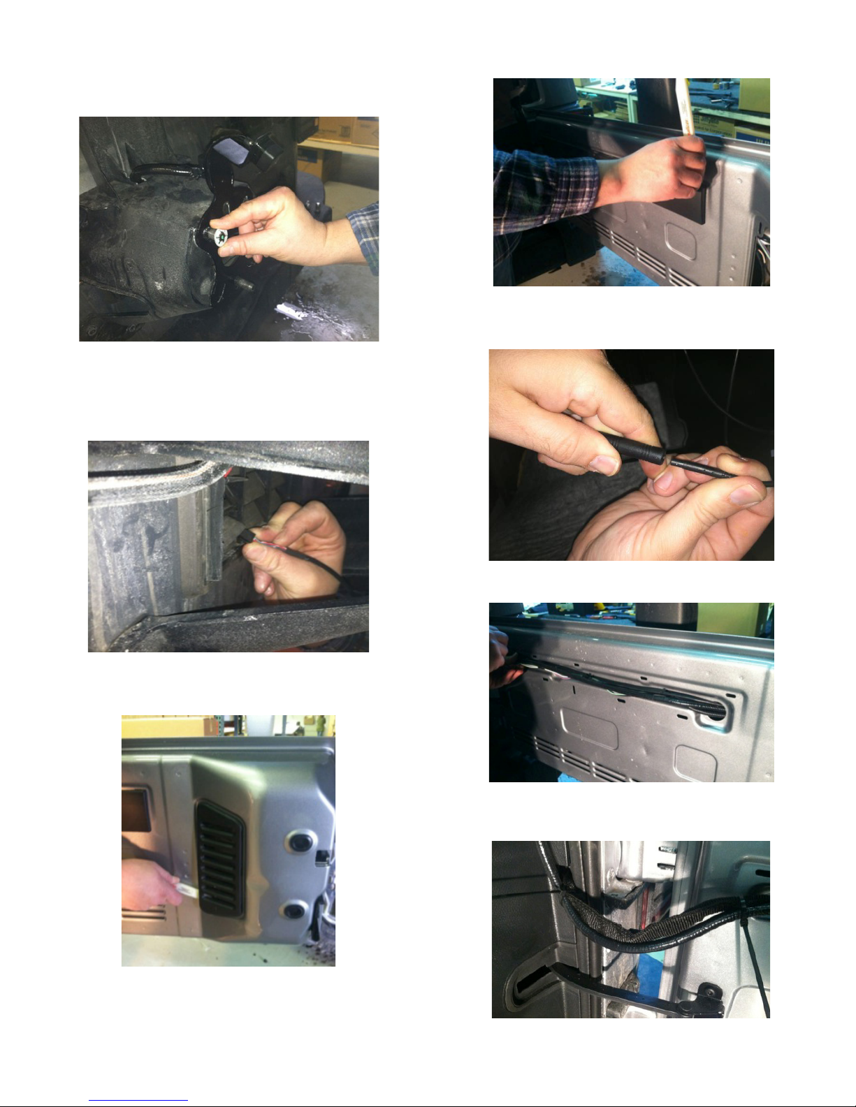
Install Camera
Step 1: Loosen lug nuts to remove spare tire.
Step 2: Slide Camera on studs placing harness end
inside of tire carrier.
Step 3: Adjust Camera head to fit your specific wheel.
Bracket is shipped in factory wheel configuration.
Adjustment Bracket for Camera Clearance using Phillips
Screwdriver and 3/8” Wrench or Socket Drive
Note: Short Bracket has been designed for Factory
offset wheels. Use the Long Bracket for wheels with
larger offsets.
8848 Instructions 12-18-14.docx Page 2 of 5
Step 4: Remove spare tire and slide (3) supplied Push
Nuts on the studs.
Step 5: Reinstall spare tire.
Install Chassis Harness
Step 6: Insert connector from Camera connector
through the rear gate vent behind tire carrier.
Step 7: Using a plastic trim removal tool, remove
interior panels on inside of rear gate.
Step 8: Pull harness through the rear gate openings.
Step 9: Use supplied Wire Ties to secure Chassis
Harness to existing harness.
Step 10: Use supplied Wire Ties to secure Chassis
Harness to existing harness.
Step 11: Use supplied Wire Ties to secure Chassis
Harness to fabric factory wire cover. CAUTION: Leave
enough slack to allow gate to open fully.
8848 Instructions 12-18-14.docx Page 3 of 5
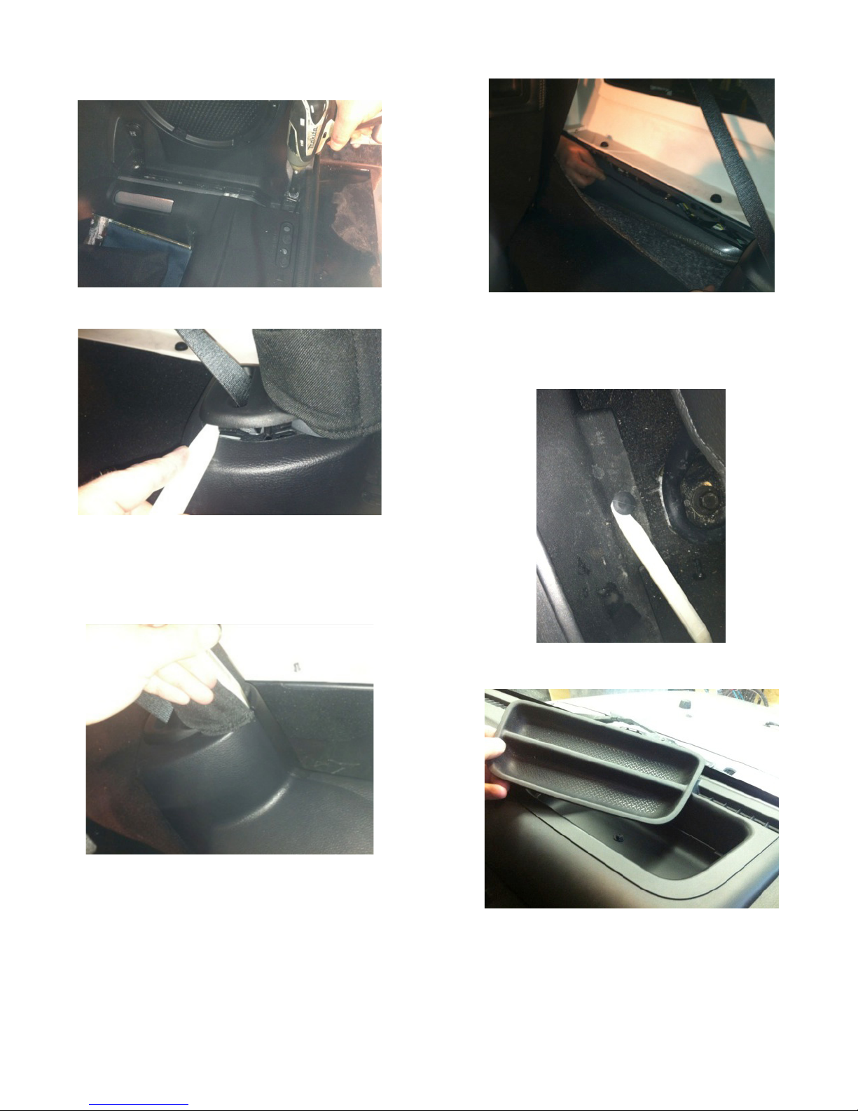
Step 12: Use a T20 Torx bit to remove subwoofer box.
Step 13: Using a plastic trim removal tool, pry off rear
seat belt closeout.
Step 14: Using a plastic trim removal tool, remove rear
access panel to expose 10mm bolt, and remove bolt.
Step 15: Pull out subwoofer box slightly to gain access
to run Chassis Harness along existing harness
Step 16: Pull back carpet and continue running Chassis
Harness forward.
Step 17: Run Chassis Harness under B-pillar cover to
passenger door sill. Use a plastic trim removal tool to
remove the (2) plastic push pins and remove passenger
sill plate/kick panel.
Step 18: Remove rubber bin insert from top of dash.

8848 Instructions 12-18-14.docx Page 4 of 5
Step 19: Remove 7mm bolt .
Step 20: Using a plastic trim removal tool, remove
window switch panel.
Step 21: Disconnect harness from window switches.
Step 22: Remove 7mm bolt.
Step 23: Remove driver knee bolster cover.
Step 24: Remove (2) 7mm bolts on both sides of the
steering column.
Step 25: Remove center stack/cluster surround.
8848 Instructions 12-18-14.docx Page 5 of 5
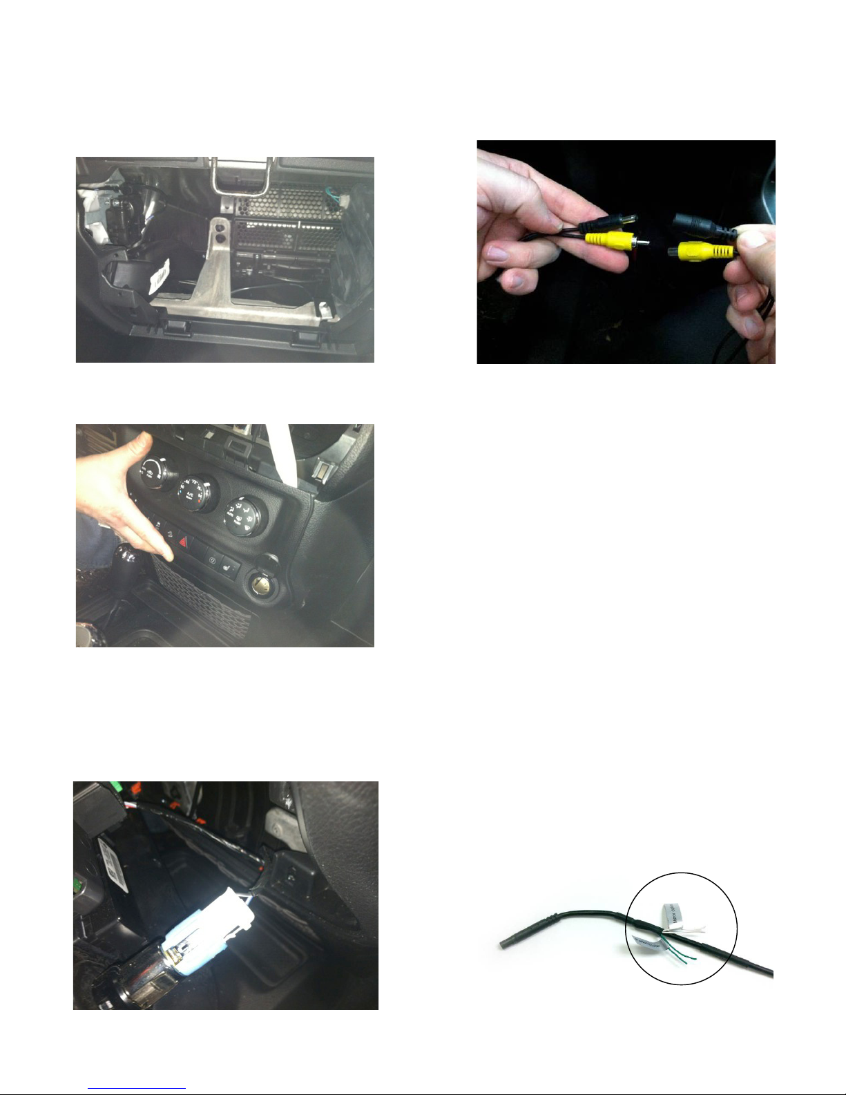
Step 26: Remove glove box for access and run Mirror
Harness toward center of dash.
Step 27: Using a plastic trim removal tool, remove
HVAC panel.
Step 28: Connecting Power harness.
Splice Red power wire to Blue/Red wire on back of
power point and Splice Black Ground to Black/White
wire. RECOMMENDED: Use solder and cover with heat
shrink tubing or use T-taps as an alternate connection
method.
Step 29: Connect Chassis Harness to Power Harness
.
Step 30: Plug the Chassis Harness RCA connector into
your aftermarket display.
Step 31: Test the system. Start vehicle and shift into
Reverse in order to check that all connections were
made properly. If all of the connections are correct you
will see the camera image displayed on your aftermarket
display. At this time camera angle can be adjusted if
needed.
Step 32: Reassemble vehicle. Follow your disassembly
steps in reverse order, taking care not to bind the
harness wiring when reinstalling trim.
NOTE: This camera has parklines or non parklines
and mirror image or non mirror image options.
Grid line options: Default setting is to display grid
lines. To remove the grid line display, connect the
two green wires near the end of the camera
harness.
Display options: (Not to be used in this application!)
Default setting is mirror image display for rearward
facing camera (rear view) installation. To change to
non mirror image for forward facing camera (front
view) connect the two white wires near the end of
the camera harness.
Green and white wires on the camera harness.
2632 Instructions 2-24-15.docx Page 1 of 3
Factory Display Camera Harness for Chrysler Town & Country, Dodge
Durango, Grand Caravan, & Ram Tradesman, Jeep Commander, Grand
Cherokee and Wrangler Factory Displays (Kit part number 9002-2632)
NOTE: Requires Chrysler/Dodge dealer to activate; see below
Applications: 2011 – current Chrysler Town & Country (RBZ, RHB, RER, REZ, RBZ, REW radios)
2011 – current Dodge Durango (RHR, RHB, RHZ, RHP radios)
2011 – current Dodge Grand Caravan (RBZ, RHB, RER, REZ, RBZ, REW radios)
2011 – current Dodge Ram Tradesman (RBZ, RHB, RER, REZ, RBZ, REW radios)
2008 – 2010 Jeep Commander (430, 730 radios)
2008 – current Jeep Grand Cherokee (430, 730, RHR, RHB, RB2, RHP radios)
2007 – current Jeep Wrangler (display radios)
Please read thoroughly before starting installation and check that kit contents are complete.
Items Included in the Kit: Tools & Su
pp
lies Needed:
Factory Display RCA Jumper Harness
Loose red and black wires (if needed)
White 22-pin Connector
These Instructions
Delphi Terminal Removal Tool #12094429 or
Small Flat Watch Repair Screwdriver
10mm Socket
Plastic Trim Removal Tool
Vehicle Service Manual (If needed)
Safety Precautions:
•Work in well ventilated area that is clear of obstructions.
•Secure vehicle with tire chucks in both front and rear of tires.
•Turn vehicle accessories OFF and ensure ignition key is in OFF position.
•Wear safety goggles and snug fitting clothes.
•Use tools only for their intended purpose and which are in good repair.
•Only perform this task if confidence, skill, and physical ability permit.
NOTE: We strive to provide accurate and up-to-date installation instructions. For the latest full color
instructions, as well as an installation video, please visit www.brandmotion.com
IMPORTANT: Use of this camera with
the factory display requires activation
by a Chrysler/Dodge dealer. See below
for Dealer Programming Instructions.
If possible, have the dealer “enable”
the camera option prior to installation.

2632 Instructions 2-24-15.docx Page 2 of 3
Step 1: Use a Plastic Trim Removal Tool to remove
console and dash trim pieces to gain access to the
radio bezel.
Step 2: Use a Plastic Trim Removal Tool to remove
radio bezel.
Step 3: Unplug all radio connectors from the radio
head unit and set radio aside.
Only complete Step 4 and 5 for 2014+ Dodge
Durango, Jeep Grand Cherokee, RAM Truck
vehicles with 52-pin radio connectors.
Step 4: Insert terminal from red wire on supplied
jumper harness into position 31 of black 52-pin
radio connector and insert terminal from black wire
on supplied chassis harness into position 32 of
black 52-pin radio connector.
Step 5: Connect male RCA of camera into female
RCA of jumper harness and proceed to the Dealer
Programming Instructions (Included).
Continue with steps 6 through 9 for vehicles
with 22-pin radio connector.
IMPORTANT: If the White 22-pin connector is
present in the vehicle and Pin 3 and/or Pin 4 are
already populated, remove the terminal(s) using
Delphi Terminal Removal Tool #12094429 or a
Small Flat Watch Repair Screwdriver and isolate
with Electrical Tape.
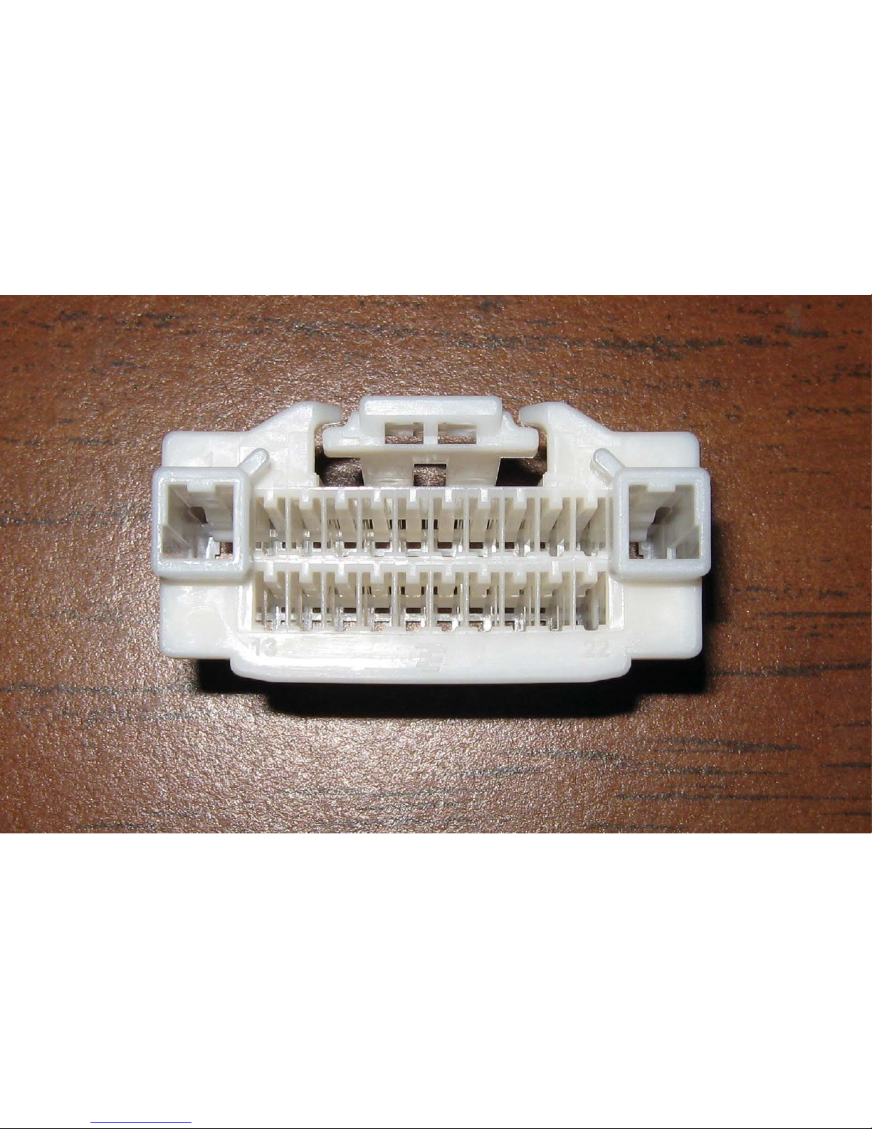
Step 6: Remove both terminals from chassis
harness. Splice provided loose red wire to chassis
harness red wire and insert terminal into pin
position 3 on the white 22-pin radio connector
(Figure 1) until it clicks securely.
Figure 1
Step 7: Splice provided loose black wire to chassis
harness black wire and insert terminal into pin
position 4 on the white 22-pin radio connector
(Figure 1) until it clicks securely.
Step 8: Connect White 22-pin Connector to radio
along with all remaining radio connectors before
reinstalling radio head unit and all trim removed.
Step 9: Connect male RCA of camera into female
RCA of jumper harness and proceed to the Dealer
Programming Instructions (Included).

2632 Instructions 2-24-15.docx Page 3 of 3
Dealer Programming Instructions
PARK VIEW REAR BACK-UP CAMERA
VEHICLE CONFIGURATION
Vehicle VIN must be updated with the sales code of the
added accessory in order to enable system functionality.
Using the DealerCONNECT website and the scan tool,
complete the procedure below:
A. Log on to https://dealerconnect.chrysler.com
B. In the “Vehicle Option” screen under “Global Claims
System” category in the “Service” tab, enter the
VIN and add the following sales code: XAC (PARK
VIEW REAR BACK-UP CAMERA) as a “Dealer
Installed Option.”
C. Confirm that the new sales code has been
successfully added to the VIN. With the scan tool
connected to both the internet (via Ethernet port or
wireless connection) and the vehicle, perform the
following steps:
D. Using the scan tool, select VEHICLE PREPARATION
and then select RESTORE VEHICLE
CONFIGURATION.
E. Follow the step by step instructions on the scan
tool to complete the Park View Rear Back-Up
Camera vehicle configuration.
Step 23: Start vehicle and shift into Reverse in
order to check that all connections were made
properly. If all of the connections are correct you
will see the camera image displayed on your
factory display.


Other manuals for 9002-8848
1
Other BrandMotion Dashcam manuals

BrandMotion
BrandMotion FLEETWORKS FLTW-7603 User manual

BrandMotion
BrandMotion ADAS+ ADAS-1100 User manual

BrandMotion
BrandMotion 9002-7752 User manual

BrandMotion
BrandMotion AHDS-7812 User manual

BrandMotion
BrandMotion FleetWorks FLTW-7637 User manual

BrandMotion
BrandMotion 9002-2906v2 User manual

BrandMotion
BrandMotion 9002-8848 User manual

BrandMotion
BrandMotion 9002-8808 User manual

BrandMotion
BrandMotion 9002-8722 User manual

BrandMotion
BrandMotion 9002-8858 User manual


