1. Introductory Information
1.1 Validity
Read fully and understand this manual before commencing work
The tasks described in this manual may be performed by skilled persons. It describes the installation,
commissioning, maintenance and warranty procedures for the following PowerFlow products:
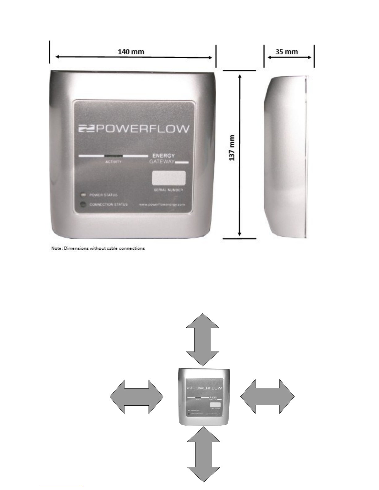
PowerFlow Energy Gateway
1.2 Additional Information
You can find additional information on the design of the complete Energy gateway system at
www.powerflowenergy.com.
1.3 Supply Parameters
The Energy Gateway is designed to be connected to an AC mains outlet via the supplied mains adaptor.
It is important to only use the supplied mains adaptor or to ensure that the input voltage to the Energy
Gateway does not exceed 5.1 V DC. Failure to comply with this instruction will result in product damage
and will void all warranties.
1.4 Appropriate Usage
The PowerFlow Energy Gateway is an internet connected energy monitoring system designed for use with
the PowerFlow Sundial battery Storage system. It cannot be used with 3rd party battery storage systems.
Do not use the Energy Gateway for any other purpose other than described in this manual.
Alternative uses or modifications to the product are expressly NOT permitted. Any other use will void any
warranty claims and operation permissions.
1.5 Safety Instructions
The following terms will be used throughout this manual. Please observe the safety instructions.
CAUTION: Risk of injury, illness or damage to property.
All work detailed by this instruction should be carefully considered.
Children may not play with or have access to the Energy Gateway.
IMPORTANT: Recommendations or advice that if not followed correctly may cause installation or system
problems and may result in additional product support. Failure to comply with these
recommendations may result in the warranty being void.