Powerlift Dumbwaiters Corporation P-100 User manual

Residential Owner’s Manual
READ THIS MANUAL BEFORE OPERATING THE DUMBWAITER
It is important that you read and understand this manual prior to operating
the dumbwaiter. If there is anything in this manual that you do not clearly
understand, contact Powerlift Dumbwaiters for clarification prior to
operating the dumbwaiter. Improper use could result in property damage
and/or serious bodily injury, or death!
2018-08-08-12:07:17
www.dumbwaiters.com
All persons who use this dumbwaiter bear the responsibility for the proper
and safe use of this product.
Misuse, deliberate or otherwise, voids all warranties, expressed or implied.
Powerlift Dumbwaiters, Inc. is not responsible for any damage, injury or
death resulting from improper installation, misuse, product modification,
additions or other changes which take place after the product has left the
manufacturer’s plant.
ASSUMPTION OF RISK
NO RIDERS
2444 Georgia Slide Road, Georgetown, CA 95634
800-409-5438 • 530-333-1953
Fax: 530-333-1055

www.dumbwaiters.com
1-800-409-5438
Page 3
Congratulations and thank you for purchasing a Powerlift Dumbwaiter!
We are a family owned company, in business for over 40 years, with a
commitment to excellence and our customers. Should you have questions or
concerns, please do not hesitate to contact us on our toll-free number in the
USA or 1-530-333-1953 for international customers. We offer free technical
support for your dumbwaiter and our staff will be happy to help you.
This owner’s manual includes information for operating and maintaining most
configurations of the Powerlift residential dumbwaiter and therefore not all
information included will apply to your dumbwaiter. If you are unclear what
configuration you have, please call us.
Serial #

www.dumbwaiters.com
1-800-409-5438
Page 4
Important Information
Identifying Parts of the Dumbwaiter (P-100 & P-200)
Identifying Parts of the Dumbwaiter (P-300 & P-500)
Basic Operation of Dumbwaiter
Recommended Maintenance Schedule
Checking & Adjusting Chain Tension (motor on the bottom)
Checking & Adjusting Chain Tension (motor on the top)
Lubricating Brake Solenoid (P-100 & P-200)
Lubricating Brake Solenoid (P-300 & MJ-500)
Troubleshooting
Wiring Diagram (2-stop / single phase)
Wiring Diagram (2-stop / three phase)
Wiring Diagram (Dynamic Brake / Single Phase)
Wiring Diagram (Dynamic Brake / Three Phase)
Wiring Diagram (3-stop / single phase)
Wiring Diagram (3-stop / three phase)
Wiring Diagram (4-stop / single phase)
Wiring Diagram (4-stop / three phase)
5
6
7
8
9
10
11
12
13
14
15
16
17
18
19
20
21
22
Table of Contents

www.dumbwaiters.com
1-800-409-5438
Page 5
1. Anyone planning to use this dumbwaiter should read the Owner’s Manual prior to operating. If you do not
have an Owner’s Manual, please visit our website to download a copy or call us to have one sent to you.
2. DO NOT allow children to use the dumbwaiter without adult supervision!
3. DO NOT operate dumbwaiter if you are under the influence of any drugs, alcohol or medication
that could affect your ability to use the dumbwaiter properly.
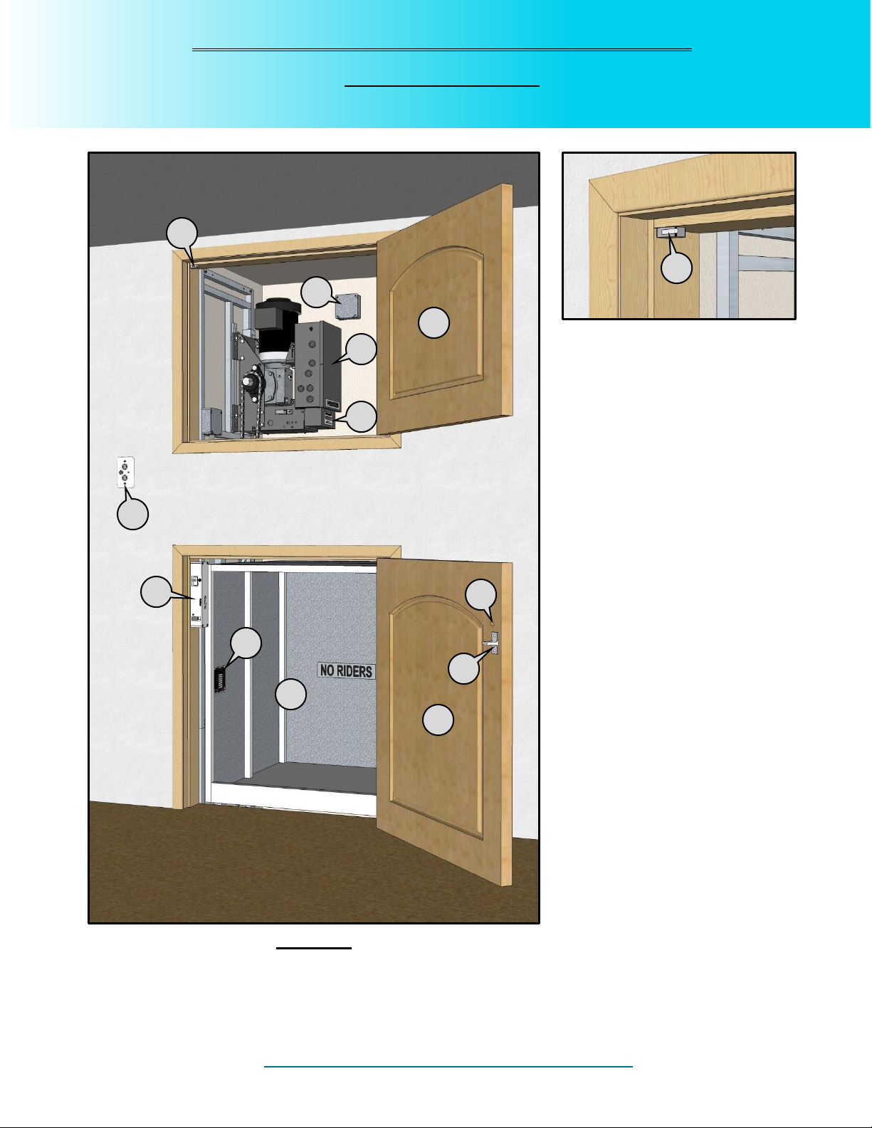
4. NEVER OPERATE DUMBWAITER if door safety switches are not working properly. Every
dumbwaiter includes door safety switches, which prevent the dumbwaiter from operating if any door is not
properly closed. The switches will also stop the dumbwaiter if any door is opened while the dumbwaiter is
in operation. If your door safety switches are not working properly, immediately unplug the dumbwaiter
and call Powerlift Dumbwaiters, Inc. to request replacement door safety switches, free of charge for the
life of the dumbwaiter. Ensure that the switches are replaced by a qualified technician.
5. NEVER OPERATE DUMBWAITER if door locks are not working properly. Every dumbwaiter includes
door locks, which prevent the doors from being opened while the dumbwaiter is in operation. If your door
locks are not working properly, immediately unplug the dumbwaiter and call Powerlift Dumbwaiters, Inc. to
request replacement door locks. Ensure that the door locks are replaced by a qualified technician.
6. NEVER USE THE DUMBWAITER if it is not operating properly. Call your service technician,
installation contractor, or Powerlift Dumbwaiters, Inc.
7. NEVER USE THE DUMBWAITER when smoke and/or fire is present.
8. DO NOT REMOVE, BYPASS, OR ALTER any switches, controls, and/or restraining devices. These
are mandated by national and local codes and safety regulations. Any tampering will void your warranty
and could result in serious injury and/or death.
9. NEVER EXTEND YOUR HANDS, ARMS, LEGS, FEET, HEAD, OR BODY INTO OPEN HOISTWAY!
Doing so could cause serious injury and/or death! Never extend foreign objects of any kind into open
hoistway. Doing so can cause damage to your dumbwaiter and/or serious injury to you!
10. NO RIDING IN DUMBWAITER CAR! Your dumbwaiter car is not intended to transport people and/or
animals. Doing so could cause serious injury and/or death!
11. NEVER OVERLOAD YOUR DUMBWAITER CAR! Your dumbwaiter is rated for a certain capacity.
Please see data plate in car.
12. Your dumbwaiter is not designed for continuous operation. Too many “starts” and “stops” could overheat
the motor and trip the breaker.
13. The dumbwaiter should be on a dedicated circuit. Too many appliances operating from the same power
source reduces the available amperage and may cause the dumbwaiter to malfunction. If your
dumbwaiter does not seem to be operating at its optimum, stop using it until it can be inspected by a
qualified technician.
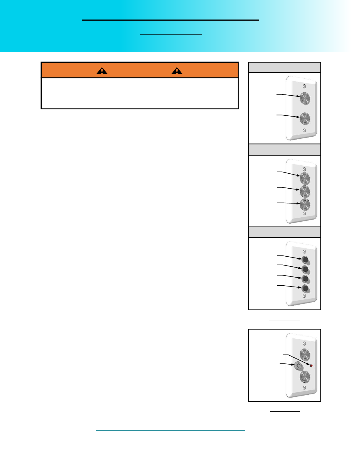
14. To prevent unauthorized use, a keyed on/off switch can be obtained from Powerlift Dumbwaiters, Inc.
15. Observe, read, and obey the warning labels, tags, and symbols, as they are provided by the manufacturer
for your safety and protection.
16. DO NOT ATTEMPT TO REPAIR the dumbwaiter yourself. Immediately stop use, disconnect power
supply and call Powerlift Dumbwaiters, Inc. to determine whether you need to contact your service
technician or installation contractor.
17. Check your local fire code. Swing Hoistway doors may be required to be fire rated and have self
closing hinges.
Important Information You Should Know
Please Read

www.dumbwaiters.com
1-800-409-5438
Page 6
1 Door safety switch
2 RCI door lock
3 RCI door lock catch
4 Hoistway door
5 Dumbwaiter car
6 Data plate
7 Call / send push buttons
8 Motor controller
9 Power supply
10 Brake solenoid cover
11 Motor access door / panel
Identifying Parts of the Dumbwaiter
P-100 & P-200
Motor on Bottom Configuration
Figure 1
3
7
5
4
11
8
9
1
6
2
1
10

www.dumbwaiters.com
1-800-409-5438
Page 7
1 Door safety switch
(see detail above)
2 Power supply
3 Motor controller
4 Brake solenoid cover
5 Motor access door / panel
6 Call / send push buttons
7 RDI door interlock
8 RDI door interlock catch
9 Hole to access emergency
override switch
10 Data plate
11 Dumbwaiter car
12 Hoistway door
Identifying Parts of the Dumbwaiter
P-300 & MJ-500
Motor on Top Configuration
Figure 2
1
7
8
12
5
11
10
6
3
2
4
9
1

www.dumbwaiters.com
1-800-409-5438
Page 8
1 Press the call/send button that corresponds with the floor you are
standing on to call the dumbwaiter car to you. (see Figure 3)
If you have a “keyed on/off lock” you have to unlock it or
the dumbwaiter will not operate. (see Figure 4)
2 Do not try to open the hoistway door until the dumbwaiter car has
arrived.
3 When the dumbwaiter car has arrived, the hoistway door will
automatically unlock and you can now open the hoistway door.
If you have a “car here light” you will see the light turn on
when the car arrives and the door unlocks. (see Figure 4)
4 Load or unload the dumbwaiter car and close the hoistway door
completely.
If the hoistway door is not completely closed the
dumbwaiter will not operate.
5 Press the call/send button that corresponds with the floor you
want to send the dumbwaiter car to.
6 Once the dumbwaiter car stops at the specified floor, the hoistway
door will automatically unlock.
7 Load or unload the dumbwaiter car and close the hoistway door
completely.
If the hoistway door is not completely closed the
dumbwaiter will not operate.
8 The dumbwaiter is now ready to be called or sent to another floor.
Basic Operation of Dumbwaiter
Please Read
NEVER EXTEND YOUR HANDS, ARMS, LEGS, FEET, HEAD
OR BODY INTO THE OPEN HOISTWAY. DOING SO COULD
DAMAGE THE DUMBWAITER AND/OR CAUSE SERIOUS
BODILY INJURY, LOSS OF LIMB, OR DEATH!
WARNING
2-Stop
3-Stop
Figure 3
4-Stop
Figure 4
2nd Floor
1st Floor
3rd Floor
2nd Floor
2nd Floor
1st Floor
1st Floor
3rd Floor
4th Floor
Keyed Lock
4th Floor
4th Floor
Car here light
3rd Floor
2nd Floor
1st Floor

www.dumbwaiters.com
1-800-409-5438
Page 9
Description of Required
Maintenance
Model
Light Use
Heavy Use
100
200
300
500
(0-49 times
per week)
(50 or more times
per week)
Lubricate idler pulley with light oil.
(see Figure 5)
Yes
No
No
No
Every 6
months
Every 3 months
Grease pillow blocks with heavy duty
bearing grease. (see Figure 6)
No
Yes
Yes
Yes
Every 6
months
Every 3 months
Lubricate brake solenoid with a
lightweight lubricant.
(see Page 12 for P-100 & P-200)
(see Page 13 for P-300 & MJ-500)
Yes
Yes
Yes
Yes
Every 12
months
Every 6 months
Check chain tension and tighten as
needed. (see Pages 10 & 11)
Yes
Yes
Yes
Yes
Every 12
months
Every 6 months
Lubricating the idler pulley:
Place a few drops of lightweight oil on the shaft
next to the pulley on each side. (see Figure 5)
Lubricating the pillow block assembly:
Using a grease gun, apply a few pumps of
heavy duty bearing grease to both lube points
on the pillow block assembly. (see Figure 6)
Recommended Maintenance Schedule
Please Read
MAKE SURE A.C. POWER IS DISCONNECTED FROM DUMBWAITER WHILE SERVICING!!
FAILURE TO DO SO COULD DAMAGE THE DUMBWAITER AND/OR CAUSE SERIOUS
BODILY INJURY, LOSS OF LIMB, OR DEATH!
WARNING
Figure 5
Figure 6
Lube Fitting
DO NOT USE WD-40!
The pillow block assembly is located at the end
of the track & rail opposite the motor.
Where the motor is at the bottom, the pillow block
assembly is just above the top floor opening.
Where the motor is at the top, the pillow block
assembly is just above the bottom floor.

www.dumbwaiters.com
1-800-409-5438
Page 10
1 From the first floor, open the hoistway door and motor access
panel / door. (see Figure 7)
2 Through the motor access panel / door open the controller and
use the “Up” contactor to move the dumbwaiter car up until the
bottom of the car is approximately 6 feet above the floor.
(see Figures 7, 9 & 10)
(see Page 14 for Contactor Operation)
3 Disconnect A.C. power from dumbwaiter.
4 Verify that both the front and back chains are taught at chest
height. (see Figure 7) If there is any slop in the chain
continue on to the next step. If the chains are both taught go
on to Step 6.
5 Using two 9/16” wrenches (15/16” for MJ-500 model), back
lock nut off and then tighten down adjustment nut until chain is
taught. Once chain is taught use a blade screwdriver or
needle nose pliers to hold the chain from twisting and tighten
lock nut up to adjustment nut securely. (see Figure 8)
NOTE: Do not overtighten the chain. If the chain slaps
during operation of the dumbwaiter, the chain is
too tight.
6 Reconnect A.C. power to the dumbwaiter.
7 Close hoistway door and motor access and use the push
buttons to send the dumbwaiter car to a floor.
If you have any questions, concerns, or
problems please do not hesitate to call us.
Maintenance
Checking & Adjusting Chain Tension
Motor on the Bottom Models
MAKE SURE A.C. POWER IS DISCONNECTED FROM
DUMBWAITER WHILE SERVICING!! YOU MUST ACCESS THE
CONTROLLER THROUGH THE MOTOR ACCESS PANEL/DOOR!!
FAILURE TO DO SO COULD DAMAGE THE DUMBWAITER
AND/OR CAUSE SERIOUS BODILY INJURY, LOSS OF LIMB, OR
DEATH!
WARNING
Figure 8
Adjustment
nut
Lock nut
First floor
hoistway door
Motor access
Adjustment
nut
Dumbwaiter
Car
#4 Check
chains here
Figure 7
Controller
Figure 10
Dynamic Brake Contactor
Press here
Figure 9
Standard Contactor
Press here

T
H
E
S
M
A
R
T
W
A
Y
T
O
B
U
Y
A
D
U
M
B
W
A
I
TE
R~THE
SMART W
AY TO BUY A DUM
BWAITER ~ THE
S
MA
RT WA
2444 GEORGIA SLIDE RD ~ GEORGETOWN, CA 95634
OFFICE 1-800-409-5438 ~ 530-333-1953 ~ FAX 530-333-1055
P
OWERLIFT
D
UMBWAITERS
C
ORPORATION
www.dumbwa ite rs .com
SINCE 1972
0DVWHU OLQN
3ODWH DQG SLQ
DVVHPEO\
5ROOHU
FKDLQ
5ROOHU
FKDLQ
*URRYHG HQGV
0DVWHU OLQN
SODWH
6SULQJ &OLS
6SULQJ &OLS 6SULQJ &OLS
*URRYHG HQGV
,QVWDOO WKH PDVWHU OLQN SODWH DQG SLQ DVVHPEO\ 3XVK WKH PDVWHU OLQN SODWH DQG SLQ
DVVHPEO\ WKURXJK ERWK HQGV RI WKH UROOHU FKDLQ ,QVWDOO WKH PDVWHU OLQN SODWH DQG
SLQ DVVHPEO\ VR WKH JURRYHG HQGV RI WKH SLQV IDFH RXWZDUG
,QVWDOO WKH PDVWHU OLQN SODWH 7KH PDVWHU OLQN SODWH ZLOO JR RQ WKH RXWVLGH RIWKH
PDVWHU OLQN DVVHPEO\
,QVWDOO WKH VSULQJ FOLS 3ODFH WKH VSULQJ FOLS RYHU WKH JURRYHV LQ WKH SLQV WKHQ XVH D IODW
KHDG VFUHZGULYHU WR SXVK WKH FOLS LQWR SODFH <RX ZLOO KHDU D FOLFN ZKHQ LW VQDSV LQWR
SODFH
+2: 72 ,167$// $
&+$,1 0$67(5 /,1.
:$51,1*
0$.( 685( 7+$7 7+( 0$67(5 /,1. ,6 )$67(1(' 6(&85(/<
)$,/85( 72 '2 62 &28/' '$0$*( 7+( '80%:$,7(5 $1'25
&$86( 6(5,286 %2',/< ,1-85< /266 2) /,0% 25 '($7+

T
H
E
S
M
A
R
T
W
A
Y
T
O
B
U
Y
A
D
U
M
B
W
A
I
TE
R~THE
SMART W
AY TO BUY A DUM
BWAITER ~ THE
S
MA
RT WA
2444 GEORGIA SLIDE RD ~ GEORGETOWN, CA 95634
OFFICE 1-800-409-5438 ~ 530-333-1953 ~ FAX 530-333-1055
POWERLIFT
DUMBWAITERS
CORPORATION
www.dumbwa ite rs .com
SINCE 1972
Master link
Plate and pin
assembly
Roller
chain
Roller
chain
Grooved ends
Master link
plate
1
2
Spring Clip
3
Spring Clip Spring Clip
Grooved ends
Install the master link plate and pin assembly. Push the master link plate and pin
assembly through both ends of the roller chain. Install the master link plate and
pin assembly so the grooved ends of the pins face outward.
Install the master link plate. The master link plate will go on the outside ofthe
master link assembly.
Install the spring clip. Place the spring clip over the grooves in the pins, then use a flat
head screwdriver to push the clip into place. You will hear a click when it snaps into
place.
1
2
3
HOW TO INSTALL A
CHAIN MASTER LINK
WARNING
MAKE SURE THAT THE MASTER LINK IS FASTENED SECURELY!
FAILURE TO DO SO COULD DAMAGE THE DUMBWAITER AND/OR
CAUSE SERIOUS BODILY INJURY, LOSS OF LIMB, OR DEATH.

www.dumbwaiters.com
1-800-409-5438
Page 11
To check & adjust chain tension requires two people, one
person will be at the top floor and one at the bottom floor.
1 With the dumbwaiter car at the bottom floor open the hoistway door
and have the person at the top floor open the motor access panel /
door.
2 Through the motor access panel / door open the controller and use
the “Up” contactor to move the dumbwaiter car up until the bottom
of the car is 3-6 feet above the floor.
(see Figures 10, 11 & 13) (see Page 14 for Contactor Operation)
3 Verify that both the front and back chains are taught. (see Figure
11) If there is any slop in the chain continue on to the next step. If
the chains are both taught go on to Step 7.
4 Close the bottom floor hoistway door and motor access panel /
door and use the push buttons to send the dumbwaiter car up to
the top floor and open the top floor hoistway door and motor
access panel / door.
5 Through the motor access panel / door open the controller and use
the “Down” contactor to move the dumbwaiter car down until the
top of the car is lined up with the bottom of the top hoistway door.
(see Figures 10, 11 & 13)
6 Using two 9/16” wrenches (15/16” for MJ-500 model), back lock nut
off and then tighten down adjustment nut two revolutions and
tighten lock nut up to adjustment nut securely using a blade
screwdriver or needle nose pliers to hold the chain from twisting
and then go back to Step 1 to verify chain tension. (see Figure 12)
NOTE: Do not overtighten the chain. If the chain slaps during
operation of the dumbwaiter, the chain is too tight.
7 Close hoistway doors and motor access then use the push buttons
to send the dumbwaiter car to a floor.
If you have any questions, concerns, or
problems please do not hesitate to call us.
Maintenance
Checking & Adjusting Chain Tension
Motor on the Top Models
MAKE SURE A.C. POWER IS DISCONNECTED FROM DUMBWAITER WHILE
SERVICING!! YOU MUST ACCESS THE CONTROLLER THROUGH THE MOTOR
ACCESS PANEL/DOOR!! FAILURE TO DO SO COULD DAMAGE THE DUMBWAITER
AND/OR CAUSE SERIOUS BODILY INJURY, LOSS OF LIMB, OR DEATH!
WARNING
Figure 13
Adjustment
nut
Lock nut
Figure 12
First floor
hoistway door
Adjustment
nut
Dumbwaiter
Car
#3 Check
chains here
Figure 11
Controller
Second floor
hoistway door
Motor
access

www.dumbwaiters.com
1-800-409-5438
Page 12
Acceptable types of lubricant for use on the brake solenoid:
Spray silicone, spray graphite, garage door lubricant,
lightweight oils such as olive oil or machine oil.
DO NOT ADJUST!
SOLENOID LEVER
LUBRICATE HERE AND
ON OPPOSITE SIDE
WITH LIGHT LUBRICANT
BRAKE DRUM
BRAKE PAD
BRAKE SHOE
SOLENOID COVER SCREWS
SOLENOID
REMOVE SOLENOID COVER FOR
EASY ACCESS TO BRAKE SOLENOID
Maintenance
Lubricating Brake Solenoid
P-100 & P-200
YOU MUST ACCESS THE BRAKE SOLENOID THROUGH THE MOTOR ACCESS PANEL/DOOR!!
FAILURE TO DO SO COULD DAMAGE THE DUMBWAITER AND/OR CAUSE SERIOUS BODILY
INJURY, LOSS OF LIMB, OR DEATH!
WARNING
RESET BUTTON
DO NOT USE WD-40!

www.dumbwaiters.com
1-800-409-5438
Page 13
Acceptable types of lubricant for use on the brake solenoid:
Spray silicone, spray graphite, garage door lubricant,
lightweight oils such as olive oil or machine oil.
Maintenance
Lubricating Brake Solenoid
P-300 & MJ-500
YOU MUST ACCESS THE BRAKE SOLENOID THROUGH THE MOTOR ACCESS PANEL/DOOR!!
FAILURE TO DO SO COULD DAMAGE THE DUMBWAITER AND/OR CAUSE SERIOUS BODILY
INJURY, LOSS OF LIMB, OR DEATH!
WARNING
DO NOT USE WD-40!
LUBRICATE HERE AND ON OTHER
SIDE WITH LIGHT LUBRICANT
SOLENOID
COVER SCREWS
SOLENOID
REMOVE SOLENOID COVER FOR
EASY ACCESS TO BRAKE SOLENOID
SOLENOID
COVER SCREWS
RESET BUTTON

www.dumbwaiters.com
1-800-409-5438
Page 14
The following instructions refer to the wiring diagrams on:
1 Verify that the dumbwaiter has a.c. power.
A. Check the circuit breaker to see if it has been tripped and reset breaker.
B. Check the overload “Reset” button, on the side of the controller box, to see if it has popped
out and reset it, if necessary, by pushing it back in.
(for “Reset” location on P-100 & 200 see Page 12)
(for “Reset” location on single phase P-300 & 500 see Page 13)
(the “Reset” on three phase P-300 & 500 is inside the controller)
2 Check for 24 volts a.c. in control box.
A. Use a volt meter to test the low voltage side of the transformer. Connecting volt meter leads
to the brown and yellow wires should show at least 24V a.c.
B. Check lighted relays 1 & 2 to see if both relays are lit.
I. If relay 2 is lit and relay 1 is not, go on to step 3.
II. If both are out, check the 2 amp fuse mounted inside the control box on the side. It is best
to remove the fuse and check for burn marks. Replace if blown.
3 Test the safety circuit.
A. On terminal bar, for 2 stop machines, short out terminals 6 and 7. For 3 and 4 stop machines,
short out terminals 1 and 2.
I. If relay 1 clicks, the safety circuit is not complete, go on to step 4.
II. If relay 1 is lit and does not click, check the connections to the push buttons.
4 Manually moving dumbwaiter car.
A. Verify all doors are closed and dumbwaiter car is not lower than the bottom floor opening or
higher than the top floor opening.
I. If dumbwaiter car is not vertically out of alignment and still does not function, please call
Powerlift Dumbwaiters, Inc.
II. If dumbwaiter car is vertically out of alignment, use the “UP” contactor to adjust the car up
or use the “DOWN” contactor to adjust the car down.
Contactor operation
With 2 stop machines, the contactor will stay in when pressed and the dumbwaiter car will
automatically go to the nearest floor when working properly. If the contactor does not stay in,
there is a low voltage problem. Please call Powerlift Dumbwaiters, Inc.
With 3 & 4 stop machines, the contactor will never stay in. If power is lost while the
dumbwaiter car is between stops, the contactors will work like a momentary contact switch,
and may be used to bump the car up or down to the nearest floor. Once the car is aligned with
an opening, the pc board will be reset and the dumbwaiter should function properly.
Troubleshooting
All Models
USING THE CONTACTORS TO MOVE THE DUMBWAITER CAR BYPASSES THE ENTIRE
SAFETY CIRCUIT. HOLDING THE CONTACTOR IN COULD DAMAGE THE DUMBWAITER
AND/OR CAUSE SERIOUS BODILY INJURY, LOSS OF LIMB, OR DEATH!
WARNING
Page 15 -- for 2-stop single phase machines
Page 16 -- for 2-stop three phase machines
Page 19 -- for 3-stop single phase machines
Page 20 -- for 3-stop three phase machines
Page 21 -- for 4-stop single phase machines
Page 22 -- for 4-stop three phase machines
This manual suits for next models
4
Table of contents
Popular Lifting System manuals by other brands

Sinoboom
Sinoboom GTZZ14EJ Maintenance manual

Northern Industrial
Northern Industrial 14226 Assembly and operating instructions

BLUM
BLUM AVENTOS HF installation instructions

Pressalit
Pressalit R8022 Mounting instruction

Palfinger
Palfinger PA19000 manual

Global Lift
Global Lift ROTATIONAL Series owner's manual