Fantek FT-6860 User manual

USER MANUAL FOR FT TOWERS 1

USER MANUAL FOR FT TOWERS 2
IMPORTANT
Read and carefully understand all points and
aspects of this manual. Loads irresponsibly can
cause lethal accidents. Installation of lifting
systems and proper use are only responsibility of
the user.
It is recommended to attach this manual with the
tower system used.
In case of doubt, consult the technical
department of FANTEK Industrial.
CONTENT
IMPORTANT ....................................................... 2
CONTACT ............................................................ 2
ILLUSTRATION INDEX ......................................... 2
WARNING ICONS ............................................... 3
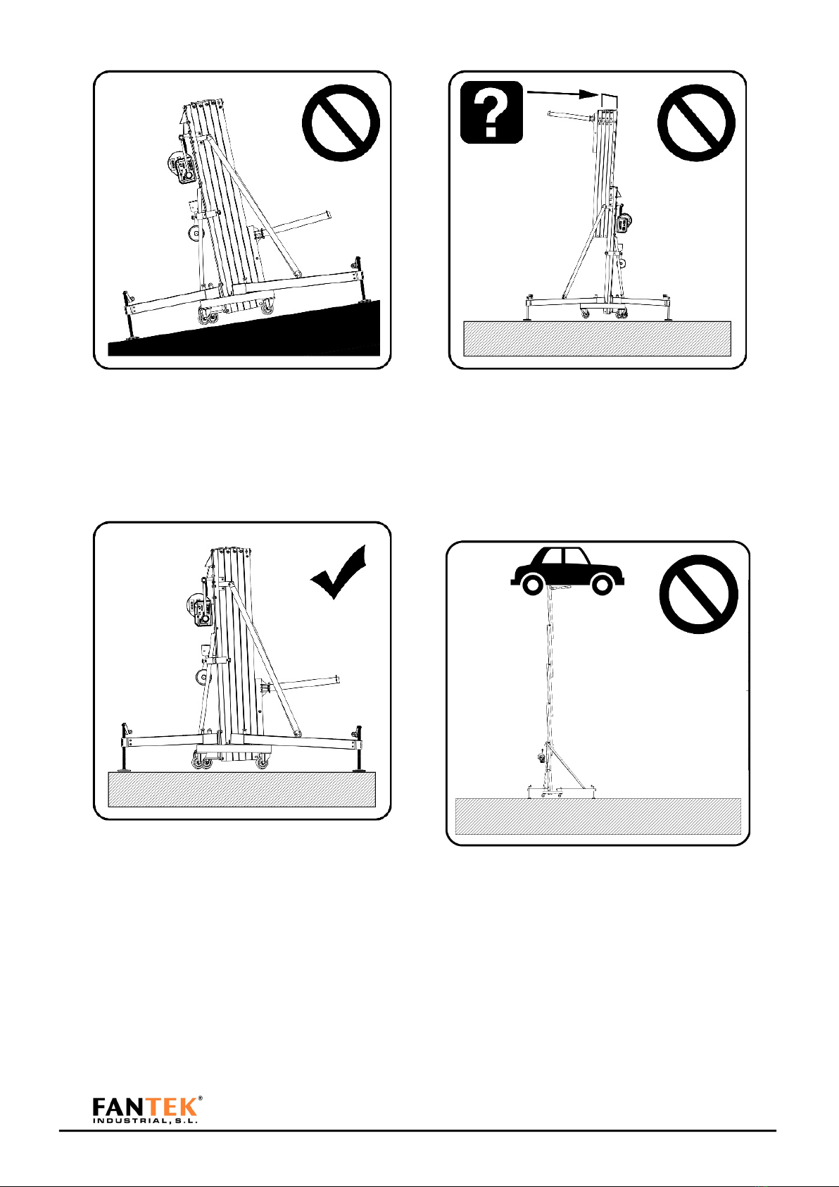
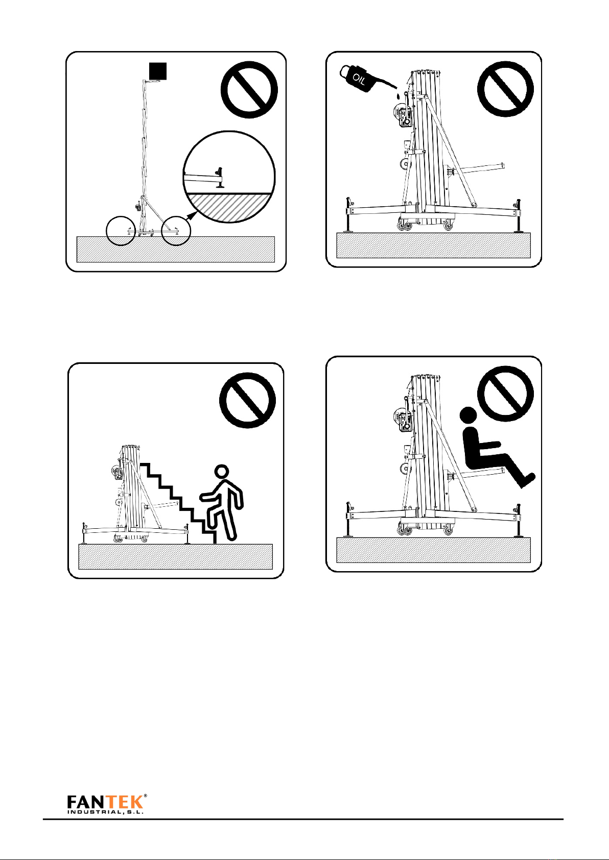
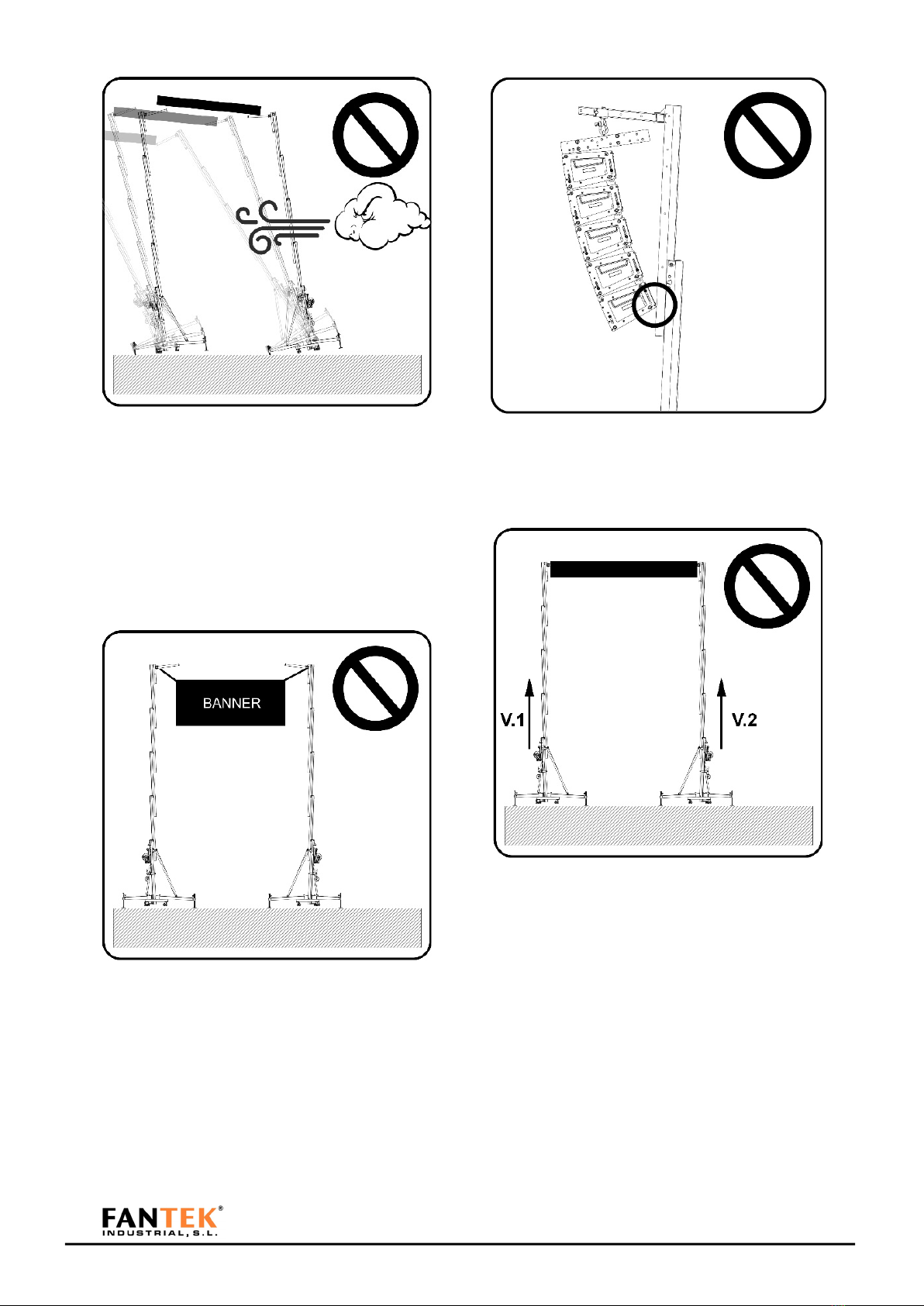
RULES AND SAFETY USE ..................................... 3
PARTS IDENTIFICATION ................................... 10
OPERATING MODES ......................................... 11
OPERATING MODE AS MECHANISM
(MECHANISM MODE) ............................. 11
OPERATING MODE AS STRUCTURE
(STRUCTURAL MODE) ............................. 11
HOW TO USE STEP BY STEP ............................. 12
LINE ARRAY ELEVATION IN MECHANISM MODE
.......................................................................... 12
LINE ARRAY ELEVATION IN STRUCTURE MODE 16
.......................................................................... 16
TRUSS SYSTEM ELEVATION IN MECHANISM
MODE ............................................................... 21
TRUSS SYSTEM ELEVATION IN STRUCTURE
MODE ............................................................... 25
.......................................................................... 25
USING THE TOWER IN STRUCTURE MODE
(WIND CONDITION) ......................................... 30
ACCESSORIES ................................................... 30
PLACING THE LOAD .......................................... 31
LOAD CHART .................................................... 32
DYNAMIC OVERLAP ......................................... 34
DGUV V17/18 NORM REGULATION.
Explanation ............................................. 35
SPECIFICATIONS ............................................... 36
DECLARACION DE CONFORMIDAD /
DECLARATION OF CONFORMITY ...................... 37
DGUV MARK .................................................... 38
CONTACT
Internet: http://www.fantek.net/
e-mail: [email protected]
ILLUSTRATION INDEX
Figure 1 ........................................................................................... 4
Figure 2 ........................................................................................... 4
Figure 3 ........................................................................................... 4
Figure 4 ........................................................................................... 4
Figure 5 ........................................................................................... 5
Figure 6 ........................................................................................... 5
Figure 7 ........................................................................................... 5
Figure 8 ........................................................................................... 5
Figure 9 ........................................................................................... 6
Figure 10 ......................................................................................... 6
Figure 11 ......................................................................................... 6
Figure 12 ......................................................................................... 6
Figure 13 ......................................................................................... 7
Figure 14 ......................................................................................... 7
Figure 15 ......................................................................................... 7
Figure 16 ......................................................................................... 7
Figure 17 ......................................................................................... 8
Figure 18 ......................................................................................... 8
Figure 19 ......................................................................................... 8
Figure 20 ......................................................................................... 8
Figure 21 ......................................................................................... 9
Figure 22 ......................................................................................... 9
Figure 23 ......................................................................................... 9
Figure 24. ...................................................................................... 10
Figure 25 ....................................................................................... 11
Figure 26 ....................................................................................... 12
Figure 27 ....................................................................................... 12
Figure 28 ....................................................................................... 12
Figure 29 ....................................................................................... 13
Figure 30 ....................................................................................... 13
Figure 31 ....................................................................................... 13
Figure 32 ....................................................................................... 13
Figure 33 ....................................................................................... 14
Figure 34 ....................................................................................... 14
Figure 35 ....................................................................................... 14
Figure 36 ....................................................................................... 14
Figure 37 ....................................................................................... 15
Figure 38 ....................................................................................... 15
Figure 39 ....................................................................................... 15
Figure 40 ....................................................................................... 15
Figure 41 ....................................................................................... 16
Figure 42 ....................................................................................... 16
Figure 43 ....................................................................................... 17
Figure 44 ....................................................................................... 17
Figure 45 ....................................................................................... 17
EN

USER MANUAL FOR FT TOWERS 2
Figure 46 ....................................................................................... 17
Figure 47 ....................................................................................... 18
Figure 48 ....................................................................................... 18
Figure 49 ....................................................................................... 18
Figure 50 ....................................................................................... 18
Figure 51 ....................................................................................... 19
Figure 52 ....................................................................................... 19
Figure 53 ....................................................................................... 19
Figure 54 ....................................................................................... 19
Figure 55 ....................................................................................... 20
Figure 56 ....................................................................................... 20
Figure 57 ....................................................................................... 20
Figure 58 ....................................................................................... 21
Figure 59 ....................................................................................... 21
Figure 60 ....................................................................................... 22
Figure 61 ....................................................................................... 22
Figure 62 ....................................................................................... 22
Figure 63 ....................................................................................... 22
Figure 64 ....................................................................................... 23
Figure 65 ....................................................................................... 23
Figure 66 ....................................................................................... 23
Figure 67 ....................................................................................... 23
Figure 68 ....................................................................................... 24
Figure 69 ....................................................................................... 24
Figure 70 ....................................................................................... 24
Figure 71 ....................................................................................... 24
Figure 72 ....................................................................................... 25
Figure 73 ....................................................................................... 25
Figure 74 ....................................................................................... 26
Figure 75 ....................................................................................... 26
Figure 76 ....................................................................................... 26
Figure 77 ....................................................................................... 26
Figure 78 ....................................................................................... 27
Figure 79 ....................................................................................... 27
Figure 80 ....................................................................................... 27
Figure 81 ....................................................................................... 27
Figure 82 ....................................................................................... 28
Figure 83 ....................................................................................... 28
Figure 84 ....................................................................................... 28
Figure 85 ....................................................................................... 28
Figure 86 ....................................................................................... 29
Figure 87 ....................................................................................... 29
Figure 88 ....................................................................................... 29
Figure 89 ....................................................................................... 31
Figure 90 ....................................................................................... 31
Figure 91 ....................................................................................... 31
Figure 92 ....................................................................................... 32
Figure 93 ....................................................................................... 32
Figure 94 ....................................................................................... 33
Figure 95 ....................................................................................... 34
Figure 96 ....................................................................................... 36

USER MANUAL FOR FT TOWERS 3
WARNING ICONS
RULES AND SAFETY USE

USER MANUAL FOR FT TOWERS 4
Figure 1
Keep hands and fingers away from moving parts
of the tower.
Figure 2
Not charge the tower without the stabilizer legs.
Figure 3
Do not lift the tower without proper leveling. To
lift a load, the tower must always be stabilized.
The wheels must not touch the ground.
Figure 4
Place the tower on a stable surface.
If the ground has a low degree of compaction
(earth, gravel, etc..) consult the section of load
data.

USER MANUAL FOR FT TOWERS 5
Figure 5
Do not use the tower on inclined surfaces that
require pieces to level the tower.
Figure 6
Mount the longest stabilizer legs in the part of
the horns. Safety pins must lock the stabilizers.
Figure 7
Lift the mast in the correct order.
Lift the mast of the tower starting always with
the carriage. The last mast lifted must be the next
to the section where the winch is placed.
Figure 8
Before placing a load, make sure that the load
never exceeds the maximum allowed. Consult
the section of load data.

USER MANUAL FOR FT TOWERS 6
Figure 9
Never move a load without leveling the tower
before.
Figure 10
Do not use ladders on the tower or leaning
against it.
Figure 11
Not grease or lubricate the mechanism of the
winch and the pulleys of the masts.
Figure 12
Not allowed to lift people or animals.

USER MANUAL FOR FT TOWERS 7
Figure 13
Do not stand under the load. The load must be
secured to the tower in order to prevent that it
cannot fall down.
Figure 14
Verify that the tower is beyond the reach of
power lines.
The tower is not electrically insulated and can
transmit currents of power lines.
On the following table is recommended the
average length between the highest part of the
structure and the power lines.
Voltage
Min. distance
Between phases
Meters
Feet
0 to 230v
1.5
4.92
230v to 400v
2.8
9.19
400v to 50Kv
3.4
11.15
50Kv to 200Kv
4.9
16.08
200Kv to 350Kv
6.5
21.33
350Kv to 500Kv
8.2
26.90
500Kv to 750Kv
11.3
37.07
750Kv to 1000Kv
14.2
46.59
Figure 15
Not use the tower as welding mass.
Figure 16
Not lift a load if there is danger of collision. Take
at least 1.5 meters on any direction to lift the
load safety.

USER MANUAL FOR FT TOWERS 8
Figure 17
The tower can be used outdoor only in structural
mode and with the loads marked as mechanism
mode (for security purpose), if the wind speed is
low and If it doesn’t put the installation at risk.
The installation is always under the responsibility
of the owner.
Figure 18
Do not use the tower as a support of banners or
another type of decoration with strong wind that
can destabilize the tower and make it falls down.
Figure 19
Prevent that the load do not touch the tower
Figure 20
Do not lift structures that require more than
one tower at different speeds
V1
≠
V2
No lift
V1
=
V2
Ok

USER MANUAL FOR FT TOWERS 9
Figure 21
The structure must be levelled correctly. If not,
the structure can fall.
Always h1 = h2
Figure 22
Under no circumstances should the tower be
descended if the cable does not have sufficient
tense. The cable should ALWAYS be tensioned in
order to release the safety systems.
Figure 23
Never use structural loads in mechanism mode.
It can result in a dangerous use and can break
internal parts of the tower.
IMPORTANT ¡!! FOR STRUCTURAL OPERATION,
USE ONLY MANUAL HOISTS

USER MANUAL FOR FT TOWERS 10
PARTS IDENTIFICATION
Figure 24.
1
Support stabilizer legs
carrier
11
Steel carrier
2
Steel cable
12
Base wheel
3
Top boost reinforcement
13
Pin horn
4
Red knob mast security system
14
Frontal leg
5
Strut reinforcement mast support
15
Steel carrier
6
Winch
16
Leveler screw
7
Tower mast
17
Leveler brace
8
Steel reinforcement strut
18
Leveler knob

USER MANUAL FOR FT TOWERS 11
9
Red knob base security system
19
Forks
10
Tower base
20
Leg carrier knob
OPERATING MODES
OPERATING MODE AS MECHANISM (MECHANISM MODE)
This mode involves lifting the load with the help of the winch. That is, the winch is driven and the pulleys
and cables are in charge of engaging and finally raising the load.
Figure 25
OPERATING MODE AS STRUCTURE (STRUCTURAL MODE)
This mode involves lifting the load with the help of a manual hoist. That is, the tower is used as a structure
that is all locked to the required working height. Once the tower is raised to this desired height, the load
must be raised with the hoist.
IMPORTANT ¡!! FOR THIS PURPOSE, USE ONLY MANUAL HOISTS

USER MANUAL FOR FT TOWERS 12
Figure 26
HOW TO USE STEP BY STEP
LINE ARRAY ELEVATION IN
MECHANISM MODE
Figure 27
Fix and secure the stabilizer legs to the base.
Figure 28
Turn the forks and adjust to the desired width.
Ensure it with the pins.

USER MANUAL FOR FT TOWERS 13
Figure 29
Place the reinforcement bars and fix them with
its pins to frontal legs.
Figure 30
Place the tower in its working position and level
until the bubble level is centered. Wheels should
not come into contact with the ground.
Calculate the load to be lifted with the tower.
An example of basic load calculation is attached.
ITEM
WEIGHT
(kg)
QUANTITY
TOTAL
(kg)
line array
accessory
5,5
1
5,5
Bumper
35
1
35
Loudspeakers
28
4
112
Cables
20
1
20
172,5
Figure 31
In this example we have obtained a weight of
172,5 kg.
With that load, see what position the load should
have on the forks of the tower. Take into account
that the inclination of the loudspeakers and the
bumper should not support any part of the
tower.
Figure 32
Choose the FT tower model. Check for the value
immediately above the load you need. With this
value, take the farthest position to which the
accessory for flying must be placed. It is
recommended that this position is always as
close to the carriage.

USER MANUAL FOR FT TOWERS 14
Figure 33
Unlock the security brake of the aluminium
carrier
Figure 34
Place the accessory in the calculated position.
Block it making sure that the screws are inserted
into the hole of the fork position.
Figure 35
Join the line array equipment to the tower.
Figure 36
Unlock the mast safety system. Operate the
winch handle to raise the load.

USER MANUAL FOR FT TOWERS 15
Figure 37
Figure 38
When the section reaches its limit, lock with the
security system and unlock the following security
system to lift the next mast. Do the same
operation until you reach the required height.
All security systems must be in locked position.
Slack the cable of the winch so that the system
can stabilize correctly.
Figure 39
Figure 40
To descend the load. Tense the cable and unlock
the first security system. Turn the winch while
keeping the safety system unlocked with your
other hand. If the safety system is not operated
with one hand, the tower will lower until it is
locked.
WARNING! If the tower is attempted to go down
without tension in the cable and any of the safety
systems are activated, a dangerous situation will
occur because the load will descend very
abruptly, being able to destabilize the whole
installation and incurring in a serious accident.
Once the load is descended, block all sections
and follow steps 4 to 1 (in that order)

USER MANUAL FOR FT TOWERS 16
LINE ARRAY ELEVATION IN
STRUCTURE MODE
Figure 41
Fix and secure the stabilizer legs to the base.
Figure 42
Turn the forks and adjust to the desired width.
Ensure it with the pins.

USER MANUAL FOR FT TOWERS 17
Figure 43
Place the reinforcement bars and fix them with
its pins to the frontal legs.
Figure 44
Place the tower in its working position and level
until the bubble level is centered. Wheels should
not come into contact with the ground
Calculate the load to be lifted with the tower. An
example of basic load calculation is attached.
ITEM
WEIGHT
(kg)
QUANTITY
TOTAL
(kg)
Line array
accessory
5,5
1
5,5
Bumper
35
1
35
Loudspeakers
28
6
168
Cables
30
1
30
238,5
Figure 45
In this example we have obtained a weight of
238,5 kg.
With that load, see what position the load should
have on the forks of the tower. Take into account
that the inclination of the loudspeakers and the
bumper should not support any part of the
tower.
Figure 46
Choose the FT tower model. Check for the value
immediately above the load you need. With this
value, take the exact position to which the
accessory for flying must be placed.

USER MANUAL FOR FT TOWERS 18
Figure 47
Unlock the security brake of the aluminium
carrier
Figure 48
Place the accessory in the calculated position.
Figure 49
Hung the manual hoist of the tower support. The
hoist must have a path equal to or greater than
the maximum height of the tower.
Figure 50
Unlock the mast safety system. Operate the
handle of the winch to raise the load.
IMPORTANT ¡!! FOR THIS PURPOSE, USE
ONLY MANUAL HOISTS

USER MANUAL FOR FT TOWERS 19
Figure 51
Figure 52
When the section reaches its end of path, lock
with the safety system and unlock the next safety
system to raise the next mast. Perform the same
operation until you reach the required height.
Figure 53
All security systems must be in locked position.
Slacken the cable of the winch so that the
system can stabilize correctly.
Figure 54
Raise the load with the hoist to the required
height.
Other manuals for FT-6860
2
This manual suits for next models
4
Table of contents
Other Fantek Lifting System manuals
Popular Lifting System manuals by other brands

Audipack
Audipack PCL-5050-10 manual

rav
rav KPH370.82 LIKTEX Original instructions

ATH-Heinl
ATH-Heinl Comfort Lift 2.30 a/s operating instructions

Dannmar
Dannmar D4-12 Installation and operation manual

Challenger Lifts
Challenger Lifts 24012 E Operation installation maintenance manual

Spanset
Spanset HH250150P Installation and operating manual