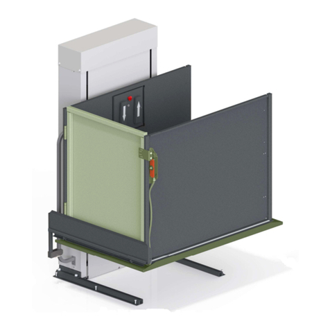
RAM Trus-T-Lift Owner's manual

TRUS-T-LIFT
SUPPLEMENTAL
MANUAL #
4
EMERGENCY
OPERATION DEVICES

RAM Elevators + Lifts 1-800-563-4382

1-800-563-4382 RAM Elevators + Lifts
Contents
Section 1: Introduction ...............................................................................................................................1
Section 2: Safety Information ...................................................................................................................1
2.1: Symbols and Definitions .................................................................................................................1
2.2: Additional Symbols .........................................................................................................................1
2.3: Safety Notes.....................................................................................................................................2
Section 4: 90 Degree Manual Crank........................................................................................................3
Section 5: UPS ............................................................................................................................................5
Section 6: Tower of Power........................................................................................................................6

RAM Elevators + Lifts 1-800-563-4382
1
Section 1: Introduction
This supplemental manual has been provided to walk you through the safe and efficient
installation of a Trus-T-Lift UPS, Tower of Power, and 90 Degree Manual Crank. Please read
this manual, as well as the main installation manual, thoroughly before installing and
operating your lift. We recommend your lift and any add-ons be installed and serviced by a
qualified technician.
Section 2: Safety Information
2.1: Symbols and Definitions
The following notations will be used through this manual to indicate areas that may present
special risks or consideration.
DANGER
Danger messages indicate an imminently hazardous situation, which, if not avoided, could
result in serious injury or even death.
Caution!
Caution messages indicate a potentially hazardous situation which, if not avoided, could
result in serious injury, death, or damage to equipment.
Note
Note messages provide information, such as reminders, general information or additional
guidelines that may provide guidance to the installer.
2.2: Additional Symbols
The following are additional symbols and conventions used through the manual:
A Detail callout, used to call attention
to a detailed mentioned in the body
of the instructions.
Step Callout, labels which step
the given diagram relates to
A
1

1-800-563-4382 RAM Elevators + Lifts
2
2.3: Safety Notes
Caution!
Read all instructions thoroughly before installation or use of this lift. Failure to follow the
instructions in this manual and the associated manuals for testing and operation could
result in serious injury or death. In addition, it will render RAM’s warranty null and void.
Do not connect or disconnect wiring while equipment power is on. Before servicing,
disconnect all power to the equipment. Failure to do so could result in significant injury or
even death.
System may start unexpectedly upon application of power. Unpredictable equipment
movement may result in serious injury or death. Use caution when applying power to the
unit during the installation process.
RAM Elevators + Lifts Inc. (RAM) disclaims any and all liability for any personal injury or
property damage resulting from the operation of a product that has been modified from the
original design. No person or company is authorized to change the design of the product
without written authorization by RAM.
Do not use an improper voltage source or a power source that provides poor quality power.
This may present a significant FIRE HAZARD and/or permanent damage to the equipment.
Do not override any of the safety devices provided with the lift. Doing so will likely lead to
serious injury or even death.
Ensure that there is nothing obstructing the carriage travel before operating the lift.
Ensure there is a minimum of 2in (50mm) and a maximum of 3in (75mm) clearance between
any part or edge of the carriage that could possibly be used as a supporting handhold and
any part of the fixed installation to prevent the trapping of a hand during the travel of the
carriage. See RAM installation drawings for details.
The lift is intended for use by people and not to be used for cargo or other purposes. Lifting
capacity is up to a maximum of 750 lb. unless otherwise noted on the lift and in RAM’s
supplied documentation. (DO NOT OVERLOAD THE LIFT). Overloading the lift will render
RAM’s warranty null and void.
This list of warnings may not be exhaustive, due care around equipment
should be observed

RAM Elevators + Lifts 1-800-563-4382
3
Section 4: 90 Degree Manual Crank
As an optional upgrade to the Trus-T-Lift, RAM offers a 90 degree manual cranking device that
allow the lift to be cranked from the side without removing the top cover.
The above figure shows the normal position of the 90 Degree Manual Crank, disengaged. While
the figure only shows the manual crank access on the left, the side the crank is on is specified
at the time of order.
Caution!
Before running or maintaining the manual crank, always unplug the power cord to
disconnect its power supply.
Operation Instructions
1) Remove the plug on the top cover that
covers the manual crank shaft.
2) Insert the 3/8” ratchet and extension
into the manual crank shaft and
engage it with the receptacle at the
end of the main drive shaft, as shown
in the figure on the next page.

1-800-563-4382 RAM Elevators + Lifts
4
3) Push and hold the ratchet and extension into the manual crank’s engaged position, as
shown in the below figure, and rotate the shaft clockwise to lower the lift, and counter-
clockwise to raise the lift.
4) After the lift platform has reached the desired landing, rotate the shaft in the opposite
direction approximately 5 times to relieve the load on the gearbox, and then retrieve the
socket ratchet and extension to disengage the crank.

RAM Elevators + Lifts 1-800-563-4382
5
Section 5: UPS
If you ordered your Trus-T-Lift with a UPS, the unit will come with the UPS pre-installed under
the top cover. To set up the UPS, press the power button located on the carriage side of the
tower.
This UPS powers the emergency lighting, emergency alarm, and interlocks, but does not power
the lift. In the envent of a loss of power, the lift will still need to be manually cranked to the
nearest landing.

1-800-563-4382 RAM Elevators + Lifts
6
Section 6: Tower of Power
The Trus-T-Lift Tower of Power
serves as a battery backup for the
lift, supplying power to the unit
when building power has been cut
off or irregular.
The Tower of Power does not come with
batteries. The tower uses 12V U1 Gel Cell
batteries, two for a standard unit and 3 for
a tall tower, all batteries must be supplied
by the installer.
On the front of the tower there are two lights, one labeled
“Building Power” which lights up red when the lift is
running on power supplied by the building, and a second
light labeled
“Battery Power”
which lights up
green when the lift
is running on stored
battery power.
When the lift is
using the TOP, the
battery power light
should always be
on, as the standard operating mode is to run on battery
power. If the building power light is on, check that the
batteries and inverter are functioning.
Installation
1) Mount the tower of power in a location where it will not be exposed to extreme cold or hot
temperatures as this will lower the performance of the top
2) Remove the front cover. There will be two cables for each battery. For each battery,
connect the red cable to the positive (+) battery terminal, and the black cable to the
negative (-) battery terminal. Once hooked up, rest the batteries on the shelves inside the
tower.
3) Plug the lift into the receptacle located on the bottom of the top enclosure
A
A

RAM Elevators + Lifts 1-800-563-4382
7
4) Plug the TOP into the building supply power
5) Turn on the inverter switch located on the bottom side of inverter.
6) Wait 105 seconds, and battery power light should come on. Once you confirm that the tower
is operating correctly, reinstall the front cover.

1-800-563-4382 RAM Elevators + Lifts
8
Other manuals for Trus-T-Lift
4
Table of contents
Other RAM Lifting System manuals
Popular Lifting System manuals by other brands

Bruno
Bruno JOEY VSL-4400G Operator's manual

Challenger Lifts
Challenger Lifts Versymmetric Installation, operation & maintenance manual

BlitzRotary
BlitzRotary Master Gear 1 operating instructions

Conquip
Conquip Goods Cage user guide

Harmar Mobility
Harmar Mobility Pinnacle SL600 Installation & service manual

Genie
Genie S-100 Service manual

RUTHMANN
RUTHMANN Steiger TB270 Operating and maintenance instructions

JLG
JLG 25AM Operation and safety manual

Palfinger
Palfinger MiniFix owner's manual

Skyjack
Skyjack SJ12 E Service manual

SCANCLIMBER
SCANCLIMBER SC500K instruction manual

PFlow Industries
PFlow Industries B Series Owner's, Installation and Maintenance Manual