Powermate Aluminum LE Series User manual

T20-030.07 For Serial Numbers 34000 and higher. PN 013900 Rev.D2
PN 339570 Rev.D2
Eng. 12/ 12/ 12

TABLE OF CONTENTS
PowerMate
®
Operation Manua
l
Section 1 - General
Warning Page............................................................................
PowerMate Description.............................................................
Delivery and Warranty Registration..........................................
Operator Training Guideline......................................................
Section 2 - Safety
Hazard Graphical Symbols........................................................
Mandatory Safety Decal Placement...........................................
Safety Precautions....................................................................
Safety Inspection......................................................................
Environment Safety.....................................................................
Loading Safety..........................................................................
Safety in Motion........................................................................
Battery Safety...........................................................................
Battery Charging Safety...........................................................
Section 3 - Instructions
LE-Series PowerMate Charging Instruction..............................
Load Recommendation Instructions........................................
Load Recommendation Chart.................................................
Loading onto a Vehicle or Loading Dock..................................
Unloading from a Vehicle or Loading Dock...............................
Taking a Load Up a Stairs.........................................................
Taking a Load Down a Stairs....................................................
Storage Procedure and Battery Care.........................................
Section 4 - LE-Series PowerMate Component Identification
LE-Series Replacement Component Drawing...........................
LE-Series Replacement Component List.................................
LE-Series with Battery Switch Component Drawing.................
LE-Series with Battery Switch Component List.......................
Screw Assembly L-1, LE-1........................................................
Screw Assembly L-2, LE-2........................................................
Screw Assembly LE-2 Carriage.................................................
Brake Assembly Kit..................................................................
Bearing Override Kit.................................................................
Section 5 - Maintenance
Maintenance After Every Year of Operation.............................
Procedure for Repairing Drive Screw Assembly......................
Override Bearing Assembly...................................................
Drive Screw Removal and Installation.....................................
Procedure to Reassemble Machine.......................................
Ballnut Removal and Replacement........................................
Installation of Sealed Batteries..............................................
Bottom Rubber Guard Replacement........................................
Switch/Charge Plug Replacement............................................
Strapbar Assembly for L-Series..............................................
Replacement Strap Installation.................................................
LE-Series Wiring Diagram.......................................................
LE-Series Wiring Diagram for Battery Switch............................
Section 6 - Specifications
LE-Series Specifications............................................................
Solidstate Controller.................................................................
Battery Specifications...............................................................
Section 7 - Accessory Installations
Battery Charger Remote Installation.........................................
PowerMate RT Cart Attachment Instruction...........................
Section 8 - Accessories
Accessories..............................................................................
Warranty...................................................................................
Declaration of Conformity............................................................
Daily Maintenance Schedule....................................................
1.01
1.02
1.02
1.03
2.01
2.02
2.04
2.05
2.05
2.06
2.06
2.07
2.08
3.01
3.02
3.03
3.04
3.05
3.06
3.07
3.08
4.01
4.02
4.03
4.04
4.05
4.06
4.07
4.08
4.09
5.01
5.03
5.04
5.04
5.05
5.06
5.07
5.08
5.09
5.10
5.10
5.11
5.12
6.01
6.02
6.03
7.01
7.02
8.01
8.03
8.04
8.05
PN 013020D2
Eng. 12/ 12/ 12
i

PowerMate
®
Operation Manua
l
WARNING
Failure to obey the Instructions and Safety
rules in this manual could result in death or
serious injury.
Read the Operating Manual completely.
Only competent, trained operators may use
this equipment.
Training is essential to understanding all
the features and capabilities of your
PowerMate, and ensure good safe work
practices.
Training courses are available through
L P INTERNATIONAL INC., please call
1-800-697-6283
PN 013100 Rev.D2
Eng. 12/ 12/ 12
1.01

Manufactured By:
L P INTERNATIONAL INC.
P.O. Box 696, 151 Savannah Oaks Drive
Brantford, Ontario, Canada N3T 5P9
TEL: (519) 759-3292 FAX: (519) 759-3298
1-800-697-6283
PowerMate
®
Operation Manua
l
PowerMate
®
MODEL L-SERIES
DELIVERY AND WARRANTY REGISTRATION
When your PowerMate
®
Motorized Stairclimber is delivered, unpack and inspect
the unit for damage or shortage of parts. If required, make note of any deficiencies on
the Delivery Acceptance Form. Registering your unit for the Warranty can be done
online at www.powermate.info. Click on Service, fill in the required fields under
Warranty and click Send Now.
Standard Equipment
2 Strapbars
Battery Charger
Wheel Brakes
Optional Equipment
Barrel Attachment
Extended Depth or Width Toe Plate
Hot Water Tank Attachment
Cylinder Attachment
WARNING The use of this equipment with any options other than
those specified in this manual may create a hazard.
The PowerMate
®
Model LE-1 is a motorized electric hand truck used for
the safe movement of heavy and awkward loads. It can move loads up and
down stairs, on and off of vehicles or loading docks and across flat surfaces.
The design takes advantage of the principle of leverage. All of the lifting of
the load is performed by the equipment.
The PowerMate®LE-1 has been designed specifically to move loads with
a very low center of gravity location. The feature of a moveable load carriage
enable the load to be kept in a controlled well-balanced position at all times.
PN 013910 Rev.D2
Eng. 12/ 12/ 12
1.02

The PowerMate
®
LE-Series Model has been tested and inspected by both the
manufacturer and the distributor to ensure the quality of manufacture and
operation. The equipment is delivered by the distributor, fully assembled and
ready for use.
The PowerMate®LE-Series Model is unique in its operation and is used to move
heavy and awkward loads. For these reasons, classroom and hands-on training
in safe and efficient operating procedures for all operators is absolutely
necessary. During the training, the operator should
LEARN HOW TO DO THE FOLLOWING:
General Use the Load Recommendation Instructions
Follow the General Safety Rules
Strapbars Adjust the location of the strapbars.
Adjust, tighten and release the straps.
Stow loose strapping when not in use.
Flat Surface Raise the wheels to incline the load back.
Reposition the load in balance over the wheels.
Move over obstacles on the floor.
Bring the load back to an upright position.
Stairclimbing Position the wheels and heelplate on a stair.
Climb up and down stairs.
Rest safely in a balanced position on stairs.
Pivot on tight landings.
Lifting Load and unload onto vehicles or loading docks.
Load and unload small vans.
Load Elevation Place loads in elevated locations.
Remove loads from elevated locations.
Two Operators Work as a team with another operator.
PowerMate
®
Operation Manua
l
PN 013190 Rev.D2
Eng. 12/ 12/ 12
OPERATOR TRAINING
1.03

The PowerMate
®
products use graphical symbols, safety colours, and signal words
throughout the Operators Manual and on the units themselves. Operators using the
PowerMate®must familiarize themselves with these symbols.
NOTICE: The signal word to address practices not
related to personal injury.
CAUTION: Indicates a potentially hazardous situation
which, if not avoided, may result in minor
or moderate injury.
WARNING: Indicates a potentially hazardous situation
which, if not avoided, could result in death
or serious injury.
DANGER: Indicates an imminently hazardous situation
which, if not avoided, will result in death or
serious injury.
Safety Alert Symbol: This symbol indicates a potential personal
injury hazard. Safety information following
this symbol must be followed to avoid
possible injury or death.
HAZARD GRAPHICAL SYMBOLS
SAFETY LABEL MAINTENANCE
Safety of the operator and surrounding environment must be considered at all times.
To that end, safety labelling on the PowerMate®must be maintained to provide
legible safety information. Clean the labels with soap and water. Do not use solvent-
based cleaners because they may damage the labels. Replace damaged or missing
labels. Replacement labels may be purchased from L P International Inc. Customer
Service Phone number 1-800-697-Mate.
PowerMate
®
Operation Manua
l
2.01 PN 013090 Rev.D2
Eng. 12/ 12/ 12

MANDATORY SAFETY LABEL PLACEMENT
Standard LE-1/LE-2 PowerMate Units
PowerMate
®
Operation Manua
l
PARTS LIST
DESCRIPTION
PART No.
QTY
ITEM
DECAL LS DISTRIBUTED BY LP055840C
11
DECAL MAINTENANCE LE-1/LE-2
065870/8012
DECAL LS LOAD DOWN/UP
05583013
DECAL LS ON/OFF055850A1
4
DECAL LS CHARGER PLUG
055820B1
5
DANGER DECAL - EXPLOSIVE ENVIRONMENT057040A16
DANGER DECAL - CRUSH HAZARD FOOT
057020A1
7
DANGER DECAL - ELECTRICAL SHOCK
057030A18
WARNING DECAL - KEEP OFF057050A19
WARNING DECAL - CRUSH HAZARD FOOT PICTOGRAM
057140A410
WARNING DECAL - SCREW GUARD057070A111
WARNING DECAL - ROTATING SHAFT/HAIR Large
057110A112
WARNING DECAL - ROTATING SHAFT/HAIR PICTOGRAM
057130A113
WARNING DECAL - PINCH POINT HAZARD
057090A114
WARNING DECAL - ROTATING SHAFT PICTOGRAM
057100A115
DECAL - SAFETY INSTRUCTION LS057190A116
DECAL - FAULT ALERTS
057160A117
DECAL - FUSE 10 AMPS057170A118
DECAL - CIRCUIT BREAKER PRESS OFF
057150A119
33
5
1
17
2
9
6
16
8
10
19 7
10
18
PN 013030 Rev.D2
Eng. 12/ 12/ 12
2.02
11
13
15
12
14
Load Down Load Up
R
NOTE: Model LE-1 shown.
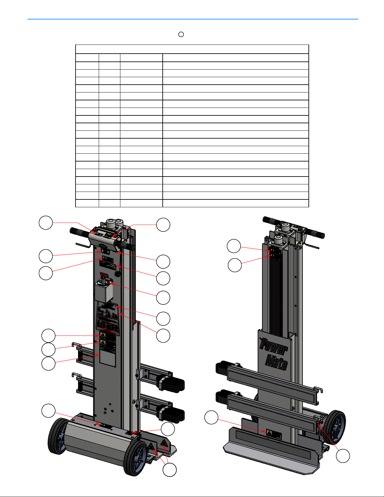
MANDATORY SAFETY DECAL PLACEMENT Fo
r
LE-1/LE-2 PowerMate Units with Battery Switch
PowerMate
®
Operation Manua
l
PARTS LIST
DESCRIPTION
PART No.
QTY
ITEM
DECAL MAINTENANCE LE-1/LE-2065870/80
11
DECAL LS CHARGER PLUG055820B12
DECAL LS LOAD DOWN/UP
05583013
DECAL LS ON/OFF
055850A14
DANGER DECAL - EXPLOSIVE ENVIRONMENT057040A1
5
DANGER DECAL - CRUSH HAZARD FOOT
057020A16
DANGER DECAL - ELECTRICAL SHOCK057030A1
7
WARNING LABEL CRUSH FOOT PICTOGRAM
057140A48
WARNING DECAL - SCREW GUARD
057070A19
WARNING DECAL - PINCH POINT HAZARD
057090A110
WARNING DECAL - MOVING PARTS Large
057060A111
WARNING DECAL - KEEP OFF057050A112
DECAL - SAFETY INSTRUCTION LS
057190A113
DECAL - FAULT ALERTS057160A114
DECAL - FUSE 10 AMPS
057170A115
DECAL - CIRCUIT BREAKER PRESS OFF
057150A116
DECAL - ROTARY SWITCH
057180A117
DECAL - DATE OF MANUFACTURE
057210A118
DECAL - CE MARK APPROVAL055860119
6
15
2.03 PN 013040 Rev.D2
Eng. 12/ 12/ 12
9
R
Load Down Load Up
12
33
2
14
18
17
19
1
5
11
10
13
7
16
88
NOTE: Model LE-1 shown.

Read all safety and operating instructions before anyone operates your PowerMate
®
Unit. Use the PowerMate®unit only as described in this manual.
Retain all safety and operating instructions for future reference. Ensure they are readily
available.
Heed all warnings in the safety and operating instructions.
Follow all installation, operation, service, and safety instructions.
Operator must have received approved training on the PowerMate®unit to be used.
Training shall include theory, practice, and testing.
Never allow unqualified or un-authorized personnel to operate the equipment.
Operator must be familiar with normal operating practices and procedures. Whenever
there is any doubt as to safety, the operator should stop the operation and not proceed
until safe conditions are restored.
Operator is responsible for maintaining proficiency on PowerMate®equipment.
Familiarity with instructions, safety procedures, maintenance practices, controls,
operation, loading, are required at all times.
WARNING: Only trained personnel shall operate PowerMate®equipment. Failure to
comply may result in possible severe injury to the operator and/or others, and damage
and/or loss of property.
Wear safety shoes. Keep hair, loose clothing, fingers and all parts of the body away
from pinch points and moving/rotating parts. Use equipment handles and controls for
manoeuvring and operation.
Operator must have good hearing and vision (with or without correction) and must have
good depth perception.
Operator must not be afflicted with any health condition(s) that might cause loss of
control or ability.
Do not operate the equipment when using alcohol or taking medication that will affect
your physical performance or judgement.
Do not eat or drink during the operation of PowerMate®equipment.
Stay alert when operating PowerMate®equipment.
No horseplay or practical jokes when operating the equipment.
Do not lift people and never ride on the PowerMate®Unit.
Do not abuse the equipment. Use PowerMate®equipment only for their intended use.
SAFETY PRECAUTIONS
READ THE MANUAL (Mandatory)
PowerMate
®
Operation Manua
l
2.04 PN 013110 Rev.D2
Eng. 12 / 12/ 12

WARNING: Do not use PowerMate
®
equipment if it is damaged. Check for
corrosion. Failure to do so may result in catastrophic failure, which may lead to
injury, damage or loss of property, and loss of life.
Inspect the PowerMate®unit (see maintenance section) prior to using to ensure the
operation can be safely completed. Insure all components of the unit are secure
and functioning.
Do not use accessories or attachments not recommended by the manufacturer, as
this may increase risk of damage and cause hazards.
Use only PowerMate®accessories best suited for the application ie: Strapbar
Attachment for box type loads, Cylinder attachment for cylindrical loads, etc.
Insure that the PowerMate®unit is charged and ready for the operation.
CAUTION: Barriers, warning signs, designated walkways or other safeguards must be
provided where pedestrians are exposed to the risk of collision.
Plan your work. Make a plan of action from picking up the load to the point where the
load is delivered. Check for doorway size, pathway surfaces, ceiling heights, tight
corners, stair step size and integrity, turn radius considerations, etc.. Always use the
recommended number of operators for a load.
Check the work site. Inspect the area to be traversed with the PowerMate®unit. Avoid
debris, rough surfaces, pot holes, bumps, steep grades, etc.. Avoid spills of any kind,
slippery surfaces, soft ground, and standing water. Observe any condition that may
cause loss of control of the PowerMate®unit leading to injury and/or property damage.
Ensure planned route for PowerMate®operation is clear of obstacles and un-involved
personnel. When visibility is obstructed use spotter person for direction instruction
and/or clear path of obstacles and un-involved personnel.
Do Not Place the PowerMate®Unit on an unstable surface. Supporting surface must
be capable of carrying the loaded PowerMate®Unit with Operator(s). Check the
condition of stairs and the edges of loading docks and vehicle beds. When moving on
or off a vehicle, be prepared for movement in the vehicle suspension system.
Do not use PowerMate®equipment in an enclosed space where oxygen, flammable,
explosive or toxic vapours are present and/or are given off by oil base paint, paint
thinner, some mothproofing substances, or in an area where flammable dust is
present.
SAFETY INSPECTION
ENVIRONMENT SAFETY
PowerMate
®
Operation Manua
l
2.05 PN 013120 Rev.D2
Eng. 12/ 12/ 12

LOADING SAFETY
SAFETY IN MOTION
CAUTION: When transiting a surface, avoid high speed turns that may cause the load
and PowerMate®unit to tip. Remember that the load must be secure to the PowerMate®
unit to ensure the load cannot shift.
When transiting the unit without a load, ensure the load strapping devices are secure,
not dangling, to prevent a trip hazard and prevent entanglement in the PowerMate®
moving parts.
Always keep your attention in the direction you are moving, monitoring clearances
above, below, and each side of the PowerMate®and load. When visibility is obstructed
use spotter person for directional instruction and/or clear path of obstacles and un-
involved personnel.
PowerMate
®
Operation Manua
l
CAUTION: Never lift a load that is over the rated capacity of the PowerMate
®
unit.
Estimate the weight and center of gravity position of the load and refer to the unit Load
Capacity Chart to ensure the load is within the loading envelope. The capacity may be
limited by the weight and strength of the operator(s). Do not operate with a load that is
beyond the operator's physical ability.
Do not attempt to increase the load capacity of the equipment by the use of chains,
rope, or other means of securing the equipment to the bed or bodies of vehicles, and
rails, wall brackets, etc.
Operators shall determine the balance of unfamiliar loads prior moving the load. Work
performed in a balanced condition is done easier and safer. New operators should gain
practice experience with lighter loads of approximately 250 lbs. with a medium center of
gravity before progressing to heavier loads. Do not raise or lower the load too far past
the balance point. Jog the equipment control switches so as not to transfer the load
weight too quickly. Training is mandatory!
Ensure the load is not damaged, properly packaged, no loose items such as tools used
in packaging the load and sharp items (such as nails) projecting from the load.
Protect the PowerMate®strapping material from sharp edges to prevent strap failure.
A
lways inspect straps prior to use. Insure the strapping latching mechanism is fully
engaged.
Verify load secureness at the beginning of use, and prior to climbing or descending with
the load. Check for any loose items or load shifting.
Never unstrap a load with the PowerMate®unit in an open (extended) condition. The
unit will fall over backwards if the wheels are not in contact with a stable surface when
the unit is unloaded.
Do not load the PowerMate®unit with a load center of gravity that is outside the side to
side limits of the unit wheels.
2.06 PN 013130 Rev.D2
Eng. 12/ 12/ 12

Stay alert. Should something break, loosen, or malfunction, on your machine, stop work
and seek qualified assistance to correct the condition. When going down a ramp or
incline, always walk ahead of the machine and use the open/close controls to engage
the rubber guard (foot) with the ground to act as a brake. Do not allow the loaded
PowerMate®to attain an un-controllable speed. When moving a PowerMate®unit down
a stair without a load, always push the wheels off the step before lowering the wheels to
the next step.
Do not compress the top urethane bumper when the machine is under load.
Lead-acid batteries contain hydrogen-oxygen gases that can be explosive and sulphuric
acid that can cause severe burns.To help avoid risk of danger and injury, observe
these precautions when handling or working with a lead-acid battery.
Wear ANSI approved safety glasses or goggles and a face shield. Wear proper clothing to
protect hands, and body. Wear appropriate rubber gloves and apron.
Never lean over a battery when testing or charging. Cigarettes, flames or sparks, could
cause a battery to explode. Keep all ignition sources away from battery. Do not strike the
sides of a battery with any spark producing item. Make sure work area is well-ventilated.
Never touch both battery terminals with bare hands at the same time. Remove rings,
watches and dangling jewelry when working with batteries. The metal in the jewelry can
cause a shock and burns if contacted with the battery terminals.
Only use insulated/non-conducting tools when making connections on a battery. Never lay
tools or other parts on top of a battery.
Because the batteries used in L P International products are of the sealed type, the battery
should be replaced if there is evidence of spillage. If there is spilled sulphuric acid present,
neutralize with baking soda. Never remove vent caps on a sealed battery. In the event of an
accident, flush with water and call a physician immediately. If venting gas is significantly
inhaled, seek immediate medical attention.
Never store batteries with explosives, flammable materials, chemicals, or food.
Protect batteries from crushing, punctures and shorting.
Do not charge or use booster cables or adjust battery connections without proper
instructions and training.
Keep batteries out of reach of children.
Do not accumulate used batteries. Dispose used batteries in accordance with local
environmental laws.
BATTERY SAFETY
SAFETY IN MOTION continued
PowerMate
®
Operation Manua
l
2.07 PN 013140 Rev.D2
Eng. 12/ 12/ 12

Before using the battery charger, read all instructions and cautionary markings on the
battery charger, battery, and product using the battery.
DANGER: Electrical equipment may be hazardous if misused. Operation of this product,
and the device it is used on, must always be done with complete knowledge of the
product instructions and safety information. Failure to do so may cause serious injury.
DANGER: RISK OF ELECTRICAL SHOCK, BURNS, OR FIRE - The battery charger
must be used as supplied. Do not use charger units if the input or output cord is cut or
frayed, or damaged in any way. Never replace, splice, or repair cables or connectors
supplied with the charger. Do not use the charger if case is damaged in any way. Do not
open the charger case for any reason. There are no user serviceable parts. Always be
sure that the charger is disconnected from the power source and battery being charged
before handling.
Your AC cord came equipped with a three-wire grounding plug (a plug that has a third
grounding pin). This plug will only fit only a grounded AC outlet. If you are unable to
insert the plug into an outlet because the outlet is not grounded contact a licensed
electrician to replace the outlet with a properly grounded outlet. Do not defeat the
purpose of the grounding plug. Pay particular attention to convenience of receptacles. If
an extension cord is necessary, use a cord with a current rating at least equal to that of
the charger. Cords rated for less amperage than the charger may overheat. Ensure the
pins of the extension cord plug are the same number, size, shape, as those on the
charger. Ensure the extension cord is wired properly and in good condition.
CAUTION: Position the charger and charger cords so that it is not tripped over, pulled,
or placed in contact with heated surfaces. Route charger cords so that they are not
likely to be walked on or pinched by items placed upon or against them. Protect the
charger from dampness or wet weather, such as rain, snow, and so on. Keep charger
away from sources of liquids, such as drinks, washbasins, bathtubs, shower stalls,
solvents, flowing water, and so on. Do not allow the charger, or any of its cords and
connectors lie in standing water such as a puddle.
CAUTION: Charge only properly maintained and rechargeable lead acid batteries of the
same voltage rating that is printed on the charger. Other battery types or voltages,
damaged batteries, or improperly maintained batteries may burst or emit dangerous
gases.
CAUTION: Only use the supplied charger on PowerMate
®
products. The charger units
supplied by L P International are internally protected against battery polarity reversal
and overload. This limits potential damage to the charger. However, the charger does
not protect against shorting or overload of external wiring or of the battery being
charged. Integrity of the PowerMate®unit wiring should be monitored during routine
inspections.
CHARGING SAFETY INSTRUCTIONS
Battery Charger
PowerMate
®
Operation Manua
l
2.08 PN 013150 Rev.D2
Eng. 12 / 12/ 12
CAUTION: Do not operate the PowerMate
®
unit while connected to the charger.
Do not overload wall outlets or extension cords, as this can result in a risk of fire or
electrical shock.
Do not operate charger if it has received a sharp blow, been dropped, or otherwise
damaged in anyway.
To reduce risk of electrical shock, unplug the charger from the outlet before attempting
maintenance or cleaning.
Disconnect the power plug by pulling the plug, not the cord.
Do not handle the plug with wet hands.
Unplug the charger when not in use.
CHARGING SAFETY INSTRUCTIONS continued
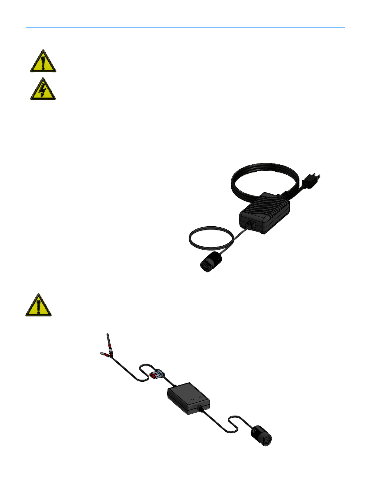
12V IN-VEHICLE CHARGER
WARNING: The In-vehicle charger cannot protect against vehicle damage caused by
faults in the wiring from the vehicle battery to the charger or faults in any other portion of
the vehicle wiring harness. The user must ensure that the wiring to the charger adheres
to the same vehicle wiring standards and safety precautions required for all vehicle
wiring.
BATTERY CHARGER
PN 400210
IN-VEHICLE REMOTE
BATTERY CHARGER
PN 400216
2.09 PN 013160 Rev.D2
Eng. 12/ 12/ 12

INSTRUCTION:
1. Provide electrical power to the Battery Charger being used.
2. De-activate the PowerMate®by depressing the Circuit Breaker Pedal located on top
of the Battery Box, moving the Circuit Breaker Toggle to the down (off) position.
Move the Control Toggle Switch to the "O"(off) position.
3. Insert the Charger Twist Lock Plug into the Charging Receptacle located in the
Handle Housing. The Plug will lock in place with a slight clockwise turn.
The charge cycle is fully automatic. The Wall Charger and the In-vehicle Electronic
Charger will indicate the charge status by LED indicators. Refer to the specific
Charger documentation.
4. To discontinue the charge cycle, dis-engage the Charger Plug from the Receptacle
by using a slight counter clockwise turn and pull.
5. The PowerMate®can be re-activated for use by moving the Circuit Breaker Toggle
to the on (up) position and moving the Control Toggle Switch to the "I"(On) position.
NOTE: The PowerMate®can remain on the Battery Charger at all times, ensuring a
fully charged unit when called upon. In any case, the Circuit Breaker Toggle
should always be in the off (down) position when the PowerMate®is not in use.
LE-SERIES POWERMATE CHARGING INSTRUCTION
PowerMate
®
Operation Manua
l
Battery Box
Circuit Breaker Pedal
Circuit Breaker Toggle
Center Prong
Small Tang Terminal
Large Tang Terminal
Small Slot Terminal
Center Hole
Large Slot Terminal
FLANGE TWIST
LOCK RECEPTACLE
TWIST LOCK
PLUG
Wall Charger
400210 In-Vehicle
Electronic
Charger
400215/6
PN 013360 Rev.D2
Eng. 12/ 12/ 12
Control Toggle Switch
3.01

LOAD RECOMMENDATION INSTRUCTIONS
The following Load Recommendation Chart (next page) outlines the recommended
maximum weight that can be moved safely by one operator in three different moving
configurations.
1. On and off vehicles or loading docks.
2. Up and down stairs.
3. Over flat surfaces.
The PowerMate®LE-1 has been designed to move loads with center of gravity
locations shown inside the shaded areas of the Load Recommendation Chart. Loads
with center of gravity locations above these areas can also be moved but do not
generally require the use of the moveable carriage.
In order to determine if your load and its specific center of gravity location can be
moved safely, complete the following three steps:
1. Determine the weight of your load in pounds (lbs.)
2. Establish where the weight is concentrated in the load. This center of gravity
location is measured in inches (in.) and is determined by
A) The distance forward from the back of the load
B) The distance up from the bottom of the load
3. On the Load Recommendation Chart locate center of gravity location for your
load. From this determine that your load does not exceed the recommended
maximum weight for that center of gravity location.
If your specific move requires two or three different moving configurations, then use
the least of the recommended maximum loads.
NOTE: Load recommendations are calculated for trained and experienced
operators and should be used accordingly.
PowerMate
®
Operation Manua
l
PN 013300 Rev.D2
Eng. 12/ 12/ 12
3.02

LE-SERIES LOAD RECOMMENDATION CHART
TAILGATE LIFTING
STAIRCLIMBING
FLAT SURFACE MOVING
PowerMate
®
Operation Manua
l
150 lbs
68 kgs
200 lbs
90 kgs
250 lbs
114 kg
200 lbs
92 kgs
250 lbs
114 kgs
350 lbs
159 kg
400 lbs
182 kgs
500 lbs
227 kgs
600 lbs
272 kg
500 lbs
227 kgs
600 lbs
272 kgs
700 lbs
318 kg
400 lbs
182 kgs
500 lbs
227 kgs
600 lbs
272 kg
150 lbs
68 kgs
250 lbs
113 kgs
450 lbs
204 kg
150 lbs
68 kgs
150 lbs
68 kgs
150 lbs
68 kg
200 lbs
91 kgs
200 lbs
91 kgs
200 lbs
91 kg
150 lbs
68 kgs
200 lbs
90 kgs
250 lbs
114 kg
200 lbs
92 kgs
250 lbs
114 kgs
350 lbs
159 kg
400 lbs
182 kgs
500 lbs
227 kgs
600 lbs
272 kg
500 lbs
227 kgs
600 lbs
272 kgs
700 lbs
318 kg
400 lbs
182 kgs
500 lbs
227 kgs
600 lbs
272 kg
150 lbs
68 kgs
250 lbs
113 kgs
450 lbs
204 kg
150 lbs
68 kgs
150 lbs
68 kgs
150 lbs
68 kg
200 lbs
91 kgs
200 lbs
91 kgs
200 lbs
91 kg
20 in
[50.8 cm]
40 in
[101.7 cm]
60 in
[152.5 cm]
6 in
[15.3 cm]
12 in
[30.5 cm]
18 in
[45.7 cm]
24 in
[61.0 cm]
PN 013310 Rev. D2
Eng. 12/ 12/ 12
3.03

LOADING ONTO A VEHICLE OR LOADING DOCK
1. Place the equipment in a safe well balanced position with the load carriage
between the heelplate and the main frame wheels.
2. Locate the equipment with the heelplate and main frame wheels out from
the rear of the vehicle or the edge of the loading dock. This will provide
clearance for the main frame wheels when they are raised. (See Diagram
“A”)
3. Pivot the equipment the equipment forward on the heelplate, just enough to
clear the vehicle/loading dock. Jog the left hand pushbutton thumb switch
“Load Down” to raise the main frame wheels until they are resting securely
on the vehicle or loading dock. Set the main frame wheel brakes. (See
Diagram “B”)
4. Jog the right hand side of the center rocker switch “Load Up” to raise the
load carriage to a more balanced position ahead of the main frame wheels.
5. Pivot the equipment backwards on the main frame wheels to raise the
heelplate off of the ground.
6. Jog the right hand pushbutton thumb switch “Load Up” to partially raise the
load. (See Diagram “C”)
7. Jog the left side of the center rocker switch “Load Down” to lower the load
carriage to a more balanced position ahead of the main frame wheels.
8. Alternate between steps #6 & 7 until the heelplate is securely resting on
the vehicle/loading dock. (See Diagram “D”)
9. Place the equipment in a safe well balanced position with the load carriage
between the heelplate and the main frame wheels.
PowerMate
®
Operation Manua
l
PN 013320 Rev.D2
Eng. 12/ 12/ 12
3.04

UNLOADING FROM A VEHICLE OR LOADING DOCK
1. Place the equipment in a safe well balanced position with the load carriage
between the heelplate and the main frame wheels.
2. Locate the equipment at the edge of the vehicle/loading dock with the
heelplate overhanging and clear of the edge. Set the main frame wheels.
3. Jog the left hand pushbutton thumb switch “Load Down” to partially lower
the heelplate.
4. Jog the right side of the center rocker switch “Load Up” to raise the load
carriage to a more balanced position ahead of the main frame wheels. (See
Diagram “D”)
5. Alternate between steps #3 & 4 to lower the heelplate to the ground out
from the rear of the vehicle or the base of the dock. (See Diagram “C”) This
will provide clearance for the main frame wheels when they are lowered.
6. Push the left side of the center rocker switch “Load Down” to lower the load
carriage to the ground. (See Diagram “B”)
7. Pivot the equipment forward on the heelplate just enough to clear the main
frame wheels.
8. Push the right hand pushbutton thumb switch “Load Up” to lower the main
frame wheels. (See Diagram “A”)
9. Place the equipment in a safe well balanced position with the load carriage
between the heelplate and the main frame wheels.
PowerMate
®
Operation Manua
l
PN 013330 Rev.D2
Eng. 12/ 12/ 12
3.05

TAKING A LOAD UP STAIRS
1. Place the equipment in a safe well balanced position with the load carriage
between the heelplate and the main frame wheels.
2. Locate the equipment with the heelplate and main frame wheels out from
the first step. This will provide clearance for the main frame wheels when
they are raised. (See Diagram “A”) Set the main frame wheels.
3. Pivot the equipment forward on the heelplate just enough to clear the step.
Jog the lift hand pushbutton thumb switch “Load Down” to raise the main
frame wheels until they are resting securely on the second step. Set the
main frame wheel brakes.
4. Jog the right side of the center rocker switch “Load Up” to raise the load
carriage to a more balanced position ahead of the main frame wheels.
(See Diagram “B”)
5. Pivot the equipment backwards on the main frame wheels to raise the
heelplate off of the ground. Jog the right hand pushbutton thumb switch
“Load Up” to raise the load until the heelplate is resting securely on the
first step up. (See Diagram “C”)
6. Alternate between steps #3 & 5 until the top of the stairs is reached. (See
Diagram “D”)
7. Place the equipment in a safe well balanced position with the load
carriage between the heelplate and the main frame wheels.
PowerMate
®
Operation Manua
l
PN 013340 Rev.D2
Eng. 12/ 12/ 12
3.06
This manual suits for next models
2
Table of contents


