POWERTEX 0,5t PGT User manual

1 1
POWERTEX Trolley model PGT/PPT-S1
GB Instruconforuse
ES Instruccionesdeuso
!
UMPGT/PPT20180913ES

2
Read through these user instructions carefully before using the trolley. Improper operation may lead to hazardous situations!
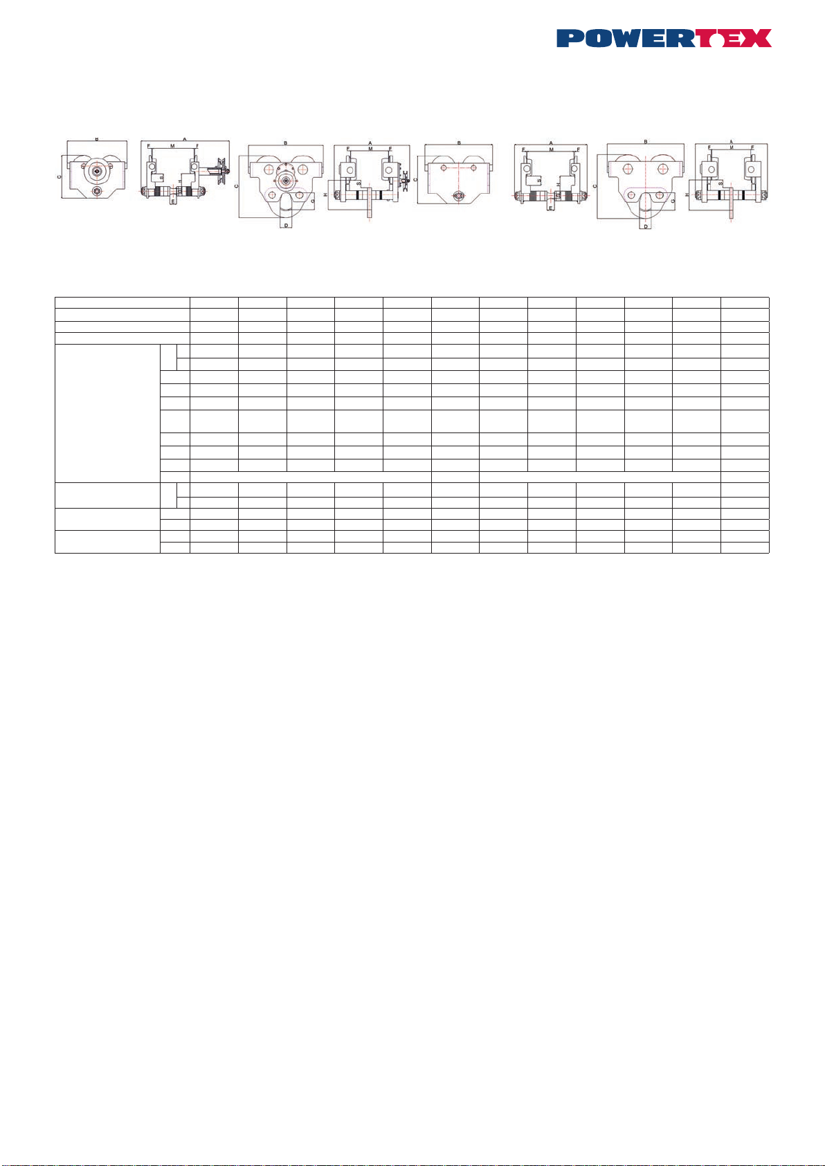
Geared trolley 0,5 - 5t Geared trolley 10t Push trolley 0,5 - 5t Push trolley 10t
Technical data
Model 0,5t PGT 1t PGT 2t PGT 3t PGT 5t PGT 10t PGT 0,5t PPT 1t PPT 2t PPT 3t PPT 5t PPT 10t PPT
Capacity load t 0,5 1 2 3 5 10 0,5 1 2 3 5 10
Test load kg 750 1.500 3.000 4.500 7.500 15.000 750 1.500 3.000 4.500 7.500 15.000
Min. radius of curve m 0,8 1 1,1 1,3 1,4 2,0 0,8 1 1,1 1,3 1,4 2,0
Dimensions mm
Aa382 398 420 456 474 402 267 289 318 345 364 380
b 508 516 526 556 566 504 393 107 424 445 457 482
B 224 270 300 356 405 485 224 270 300 356 405 490
C 159 190 218 262,5 292 395 159 190 218 262,5 292 395
D-----72-----72
H57.5 (55.5) 67 (65) 74 (72) 87 (85) 95.5 (93.5) 189 57.5 (55.5) 67 (65) 74 (72) 87 (85) 95.5 (93.5) 189
S 30 35,5 36 38 41 45 30 35,5 36 38 41 45
E 27 29 43 (35.6) 46 56 - 27 29 43 (35.6) 46 56 -
G18 (22) 22 (26) 28 (32) 34 (38) 39 (43) 112 18 (22) 22 (26) 28 (32) 34 (38) 39 (43) 112
F 1.5-3 2-3.5 1.5-3 2-3.5
I beam width range M a50-180 66-188 88-200 100-205 114-212 124-203 50-180 66-188 88-200 100-205 114-212 124-203
b 176-305 184-305 194-305 200-305 208-305 124-305 176-305 184-305 194-305 200-305 208-305 124-305
Net weight kg a9 15 22 34 49 87 6 15 18 30 44 86
b 9,5 16 23,5 38 56 94 6,5 17 20 34 50 90
Gross weight kg a9,5 15,55 22,8 35 50,1 95 6,25 15,3 18,3 30,45 44,65 67
b10 16,55 24,3 39 57,1 102 6,75 17,3 20,3 34,45 50,65 98
Safety factor: 4:1
Static test coefcient: WLL x 1,5
Generally according to EN 13157
1. Proper usage
Usage:
The trolleys can be used for I-beams with plane anges (such as IPE, HEA or HEB types) or beams with sloping anges (such as INP-beams).
The possible width ranges are shown in the data tables.
The trolley is a rolling and geared chassis for attaching to lifting gear for use inside.
It is not suitable for continuous operation.
It is not suitable for use in rooms where there is a potential risk of explosions.
It is not suitable for use in aggressive atmospheres.
The unit should be installed if possible in a covered room. If it is installed outdoors a roof is to be provided or the unit is to be covered.
Modications to the lifting gear are only permitted with our express consent in writing.
Refer to the technical data and function description.
Safety instructions
Operation and servicing must be left strictly to: authorized, trained personnel.
• Only install the trolley on girders whose load capacity has been checked previously.
• Do not install the trolley on tapered girders.
• Stops on the ends of girders must not be moved or removed.
• Do not transport personnel or allow personnel to be located in the danger area.
• Do not allow the load to swing.
• Do not stand under a raised load.
• Never reach into moving parts.
• Defects are to be rectied immediately by trained personnel.
• Never leave the load off the ground without supervision.
• Loads may only be raised vertically. Do not raise loads at an angle.
• Do not use the trolley to pull items out of other items, release them or drag them sideways.
• The trolley may only be used to push or pull the load.
• Do not exceed the load capacity set out in the technical data.
• Check the raceway width and adjust the distance between the chassis anges using the gures in the table.
• The hand chain is only designed for moving the load attached to the lifting gear and must not be used for any other purpose.
• Never slew the load off the ground without supervision.
• High strength parts such as the chain, hook and gear parts must not come into contact with free hydrogen, acids, alkalis, vapour or very
aggressive cleaning products. They may become brittle and fracture.
• Conduct a risk analysis before use and verify EC conformity.
• Working temperature: -10°C to +50°C.
POWERTEX Trolley PGT-S1 and PPT-S1 0,5 – 10 ton
Mounting / Instruction for use (GB) (Original instructions)

2 3
The chassis chain (hand chain)
• is only designed for moving the trolley and must not be used for any other purposes.
• must not be used to attach a load.
• must not be drawn over sharp edges.
• must not be twisted.
• Before you use the trolley check that it is correctly mounted on the girder.
• Conduct a visual inspection of the rollers every day. Pay special attention to the lateral play between the raceway girder and the rollers.
• Check that the bolts are secure and that the traverse is secure.
Commissioning
Function description
The roller chassis may only be pulled on the load, the load hook or the load chain of the lifting gear.
The roller chassis is to be attached to a horizontal raceway girder.
The raceway girder must be at and horizontal.
The chassis width may be adjusted by spacing to the relevant girder width.
The chassis is designed without a brake.
The attached load may be moved either by pushing or pulling the load (rolling chassis) or by pulling the hand chain (gear chassis).
The movement speed should be such that the load can be braked by the user at any time.
Assembly and installation of the trolley on the girder
The trolleys can be adjusted to various girder ange widths.
1. Establish the girder dimensions (M) (ange width).
2. Check conformity with the data sheet.
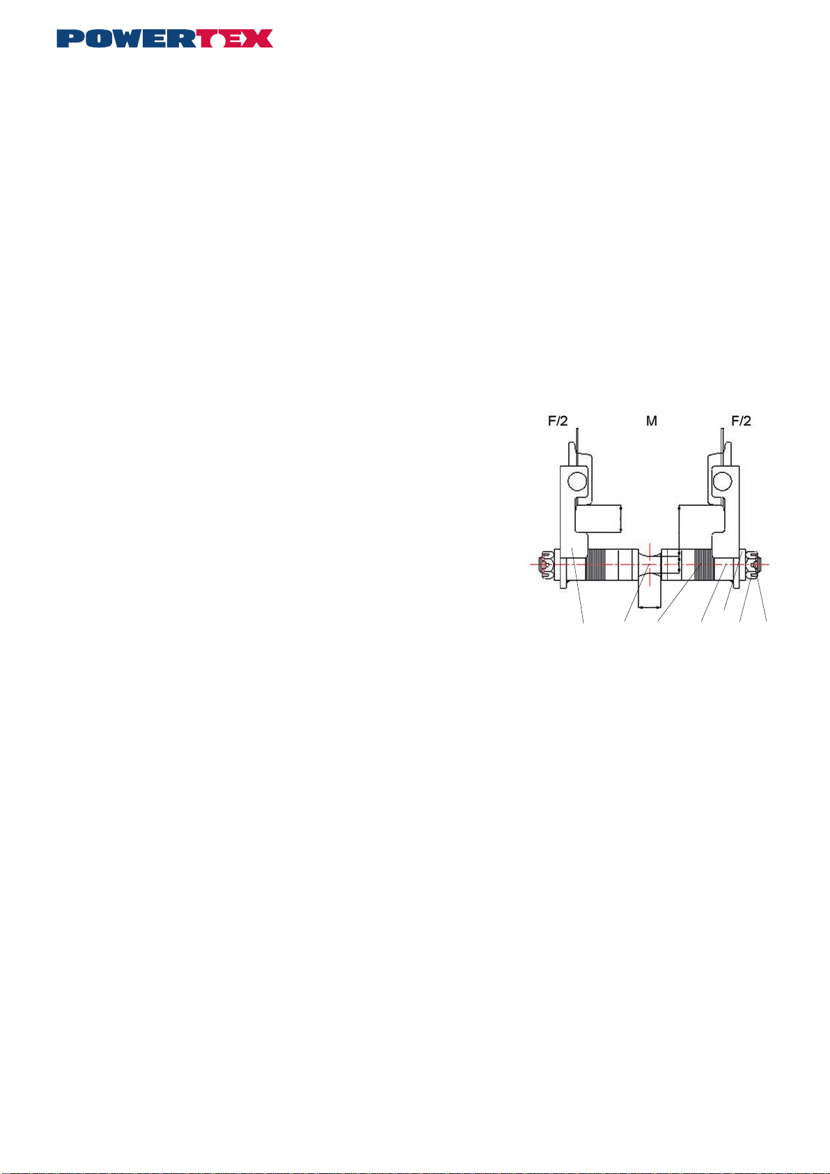
Dismantled the trolley
• Unscrew the load bolt (undo the split pin (6), lock nut (5) and load bolt (2)).
• Set the track width. The distance between the rims (F) must be approx. 2 mm.
larger on chassis weighing up to 2000 kg than the actual (measured) girder ange width.
• There are adjusting washers (3), (4) on the load bolt.
• The spacing dimension (M) is achieved by pushing adjusting washers from
outside to inside (M is increased) or from inside to outside (M is reduced).
Do not leave out any adjusting washers.
• Tighten the lock nut (5) and secure it with the split pin.
Installation on the girder
Adjust the side plates (1) of the chassis to width “M” with the load bolt (2), adjuting washers (3)
and (4), spacer tube (7) and lock nut (5) and t them. Tighten the lock nuts and push the unit
on to the front of the girder ange. If this is not possible, the chassis can also be installed on
to the raceway girder from underneath. The lock nut on the side without the drive unit must be
removed for this purpose. Pull the chassis halves apart until the chassis can be pushed on to
the girder ange from underneath. Then push the chassis together again to the correct track
width, tighten the lock nut and secure it with the split pin.
The side plates should not be stressed by the lock nut but should still be able to move on the load bolt (2).
Commissioning
Ensure that the chains are correctly positioned; they must not be twisted and must hang freely.
Always refer to the operating manual of the lifting gear you are using.
The open meshing on the drive unit should be greased.
Function test:
Carefully move the chassis to the limit position and check the position of the limit stops.
Operation
Move the load by pulling the hand chain or by pushing the load.
Do not stand under a raised load.
Media / Recommended lubricants
Recommended lubricant for greasing points:
- Meshing, drive pinion
Multi-purpose grease DIN 51825 T1 K2K
After use the lubricant must be disposed of in compliance with the statutory regulations.
If the product is modied in any way, or if it is combined with a non-compatible product/component, CERTEX Group take no responsibility for the
consequences in regard to the safety of the product.
1 2 3 7 4 5 6

4
Inspection and servicing instructions
Safety instructions
Remove all the strain from the girder trolley by suitable means before carrying out inspection and servicing work
Instruction Grey Label
To change your new POWERTEX Trolley to Black Line:
If the product should be used in dark environments, add the grey label on the product’s nameplate like this.
The data on the nameplate should ALWAYS be visible, and must NOT be covered.
Disposal:
After the trolleys have been taken out of use, the parts of the block and tackle
are to be recycled or disposed of in compliance with the statutory regulations.
Inspection intervals
Conduct an expert inspection
before commissioning Servicing and inspection work
Daily
Visual inspection of rollers (for signs of cracks and deformation)
Visual inspection of the chain
Function of the unit
Adjustment range, visual inspection of the track width lateral play
Quarterly The rollers are tted with ball bearings that are lubricated for life
Every six months
Check the condition of the hand chain (remove sharp edges as they constitute an injury risk)
Check screw connections.
Grease the meshing on the rollers and drive pinion.
Every year Check that the model plate is completely legible.
Have the annual test carried out by an expert
The service life of the unit is limited, worn parts must be replaced promptly by an expert.
Contact your dealer for spare parts in general.
Problem Cause Servicing and inspection work
The girder trolley can only be
moves with difculty.
No grease in the bearings and meshing. Visuel inspection of rollers (for signs of cracks or deformation)
Visual inspection of the chain
Function of the unit
Adjustment range, visual inspection of the track width lateral play
Dirt or other foreign bodies on load girder.
Girder deformed
4 5
Lea estas instrucciones de usuario atentamente antes de utilizar el carro. ¡Un uso inadecuado puede provocar situaciones peligrosas!
Carro engranado 0,5 - 5 t Carro engranado 10 t Carro manual 0,5 - 5 t Carro manual 10 t
Especicaciones técnicas
Modelo 0,5 t PGT 1 t PGT 2 t PGT 3 t PGT 5 t PGT 10 t PGT 0,5 t PPT 1 t PPT 2 t PPT 3 t PPT 5 t PPT 10 t PPT
Capacidad de carga t 0,5 1 2 3 5 10 0,5 1 2 3 5 10
Carga de prueba kg 750 1 500 3 000 4 500 7 500 15 000 750 1 500 3 000 4 500 7 500 15 000
Radio mínimo de curva m 0,8 1 1,1 1,3 1,4 2,0 0,8 1 1,1 1,3 1,4 2,0
Dimensiones mm
Aa382 398 420 456 474 402 267 289 318 345 364 380
b 508 516 526 556 566 504 393 107 424 445 457 482
B 224 270 300 356 405 485 224 270 300 356 405 490
C 159 190 218 262,5 292 395 159 190 218 262,5 292 395
D-----72-----72
H57,5
(55,5) 67 (65) 74 (72) 87 (85) 95,5
(93,5) 189 57,5
(55,5) 67 (65) 74 (72) 87 (85) 95,5
(93,5) 189
S 30 35,5 36 38 41 45 30 35,5 36 38 41 45
E 27 29 43 (35,6) 46 56 - 27 29 43 (35,6) 46 56 -
G18 (22) 22 (26) 28 (32) 34 (38) 39 (43) 112 18 (22) 22 (26) 28 (32) 34 (38) 39 (43) 112
F 1,5-3 2-3,5 1,5-3 2-3,5
Rango de ancho,
viga en I Ma50-180 66-188 88-200 100-205 114-212 124-203 50-180 66-188 88-200 100-205 114-212 124-203
b 176-305 184-305 194-305 200-305 208-305 124-305 176-305 184-305 194-305 200-305 208-305 124-305
Peso neto kg a9 15 22 34 49 87 6 15 18 30 44 86
b 9,5 16 23,5 38 56 94 6,5 17 20 34 50 90
Peso bruto kg a9,5 15,55 22,8 35 50,1 95 6,25 15,3 18,3 30,45 44,65 67
b 10 16,55 24,3 39 57,1 102 6,75 17,3 20,3 34,45 50,65 98
Factor de seguridad: 4:1.
Coeciente de prueba estática: CLT x 1,5
En general, conforme a EN 13157.
1. Uso previsto
Uso:
Los carros se pueden emplear para vigas en I con alas planas (como IPE, HEA o HEB) o vigas con alas inclinadas (como las vigas INP).
En las tablas de datos se muestran los posibles rangos de ancho.
El carro es un chasis engranado y rodante que permite acoplar los equipos de elevación para usarlos en interiores.
No es apto para uso continuo.
No es apto para usarse en estancias con riesgo potencial de explosión.
No es apto para emplearse en atmósferas agresivas.
La unidad, a ser posible, debería instalarse en una estancia cubierta. Si se instala al aire libre, habrá que colocar un tejado o cubrir la unidad.
El equipo de elevación solo podrá modicarse con nuestro consentimiento explícito por escrito.
Consulte las especicaciones técnicas y la descripción del funcionamiento.
Instrucciones de seguridad
El manejo y el mantenimiento deben realizarse exclusivamente por personal cualicado y autorizado.
• Instale el carro únicamente en vigas cuya capacidad de carga se haya comprobado previamente.
• No instale el carro en vigas cónicas.
• No mueva ni retire los topes de los extremos de las vigas.
• No transporte personas ni permita que haya nadie en la zona de peligro.
• No permita que la carga se balancee.
• No permanezca debajo de cargas suspendidas.
• No intente tocar las piezas móviles.
• Los defectos debe solucionarlos de inmediato personal cualicado.
• No deje la carga suspendida sin supervisión en ningún momento.
• Las cargas solo deben elevarse verticalmente. No eleve las cargas en ángulo.
• No use el carro para sacar artículos de otros artículos, liberarlos o arrastrarlos lateralmente.
• El carro solo debe usarse para tirar o empujar la carga.
• No supere la capacidad de carga indicada en las especicaciones técnicas.
• Revise el ancho de rodadura y ajuste la distancia entre las alas del chasis usando las cifras de la tabla.
• La cadena manual está diseñada exclusivamente para desplazar la carga acoplada al equipo de elevación. No debe utilizarse con ninguna
otra nalidad.
• No eleve la carga del suelo sin supervisión.
• Las piezas de alta resistencia como la cadena, el gancho o el engranaje no deben entrar en contacto con hidrógeno libre, ácidos, álcalis,
vapor ni detergentes muy agresivos. Podrían debilitarse y romperse.
• Realice un análisis de riesgos antes de utilizar este dispositivo y compruebe la conformidad CE.
• Temperatura operativa: de -10 °C - a +50 °C.
POWERTEX Carro PGT-S1 y PPT-S1 0,5 – 10 toneladas
Instrucciones de montaje/uso (ES)
6
La cadena del chasis (cadena manual)
• está diseñada exclusivamente para desplazar el carro y no debe utilizarse con ninguna otra nalidad.
• no debe utilizarse para acoplar una carga.
• no debe arrastrarse sobre bordes alados.
• no debe retorcerse.
• Antes de utilizar el carro, asegúrese de que está correctamente montado en la viga.
• Realice una inspección visual de los rodillos a diario. Preste especial atención a la holgura lateral entre la viga de rodadura y los rodillos.
• Asegúrese de que los pernos están bien jos y que el recorrido es seguro.
Puesta en servicio
Descripción del funcionamiento
El chasis de los rodillos solo puede colocarse en la carga, el gancho de la carga o la cadena de carga del equipo de elevación.
El chasis de los rodillos debe acoplarse a una viga de rodadura horizontal.
La viga de rodadura debe estar plana y horizontal.
El ancho del chasis debe ajustarse separando según al ancho de viga correspondiente.
El chasis está diseñado sin freno.
La carga acoplada se puede mover tirando o empujando la carga (chasis rodante) o tirando de la cadena manual (chasis engranado).
Asegúrese de que la velocidad de movimiento es tal que el usuario puede frenar la carga en cualquier momento.
Montaje e instalación del carro en la viga
Los carros se pueden ajustar a distintos anchos de ala.
1. Determine las dimensiones de la viga (M) (ancho de ala).
2. Compruebe que cumple los datos de la cha.
Carro desmontado
• Desatornille el perno de la carga (suelte la clavija hendida (6), la tuerca de cierre (5)
y el perno de carga (2)).
• Fije el ancho de vía. La distancia entre los bordes (F) debe ser aprox. 2 mm
mayor en los chasis de hasta 2000 kg de peso que el ancho real (medido) del ala.
• El perno de carga cuenta con arandelas de ajuste (3), (4).
• La separación (M) se logra empujando las arandelas de ajuste desde fuera
hacia dentro (M aumenta) o de dentro hacia fuera (M se reduce).
No se salte ninguna arandela de ajuste.
• Apriete la tuerca de cierre (5) y fíjela con la clavija hendida.
Instalación en la viga
Ajuste las placas laterales (1) del chasis al ancho «M» con el perno de carga (2), las
arandelas de ajuste (3) y (4), el tubo separador (7) y la tuerca de cierre (5) y encájelas.
Apriete las tuercas de cierre y empuje la unidad hacia la parte delantera de la ala. Si no
fuera posible, el chasis se puede instalar también en la viga de rodadura desde abajo. Para
ello, se debe retirar la tuerca de cierre del lateral sin la unidad de transmisión. Separe las
mitades del chasis hasta que se pueda empujar el chasis al ala desde abajo. Después,
vuelva a juntar y colocar el chasis en el ancho de vía correcto, apriete la tuerca de cierre y
fíjela con la clavija hendida.
La tuerca de cierre no debería ejercer presión sobre las placas laterales, que deberían poder moverse en el perno de carga (2).
Puesta en servicio
Asegúrese de que las cadenas están bien colocadas. No deben estar retorcidas y han de colgar libremente.
Consulte siempre el manual operativo del equipo de elevación que esté empleando.
La malla abierta de la unidad de transmisión debe engrasarse.
Prueba de funcionamiento:
Mueva con cuidado el chasis hasta la posición límite y compruebe la posición de los topes límite.
Funcionamiento
Mueva la carga tirando de la cadena manual o empujando la carga.
No permanezca debajo de cargas suspendidas.
Lubricantes/líquidos recomendados
Lubricante recomendado para los puntos de engrase:
- Malla, piñón de ataque
Grasa multifunción DIN 51825 T1 K2K
El lubricante usado se debe eliminar conforme a los requisitos normativos.
Si se modica en modo alguno el producto o si se combina con componentes/productos no compatibles, CERTEX Group no asume ninguna
responsabilidad por las consecuencias en cuanto a la seguridad del producto.
1 2 3 7 4 5 6

6 7
Instrucciones de inspección y mantenimiento
Instrucciones de seguridad
Retire toda la tensión del carro de viga con los medios necesarios antes de realizar las labores de inspección y mantenimiento.
Instrucciones, etiqueta gris
Para cambiar su nuevo carro POWERTEX a la versión Black Line:
Si el producto debe emplearse en entornos oscuros, añada la etiqueta gris a la placa descriptiva del producto.
Los datos de la placa descriptiva deberían estar SIEMPRE visibles y NO deben cubrirse bajo ninguna circunstancia.
Eliminación:
Cuando se hayan retirado del servicio los carros, las piezas del bloque y el aparejo
se deben reciclar o eliminar conforme a los requisitos normativos.
Intervalos de inspección
Realice una inspección
experta
antes de la puesta en servicio
Labores de mantenimiento e inspección
Diario
Inspección visual de los rodillos (por si presentaran grietas o deformación)
Inspección visual de la cadena
Funcionamiento de la unidad
Rango de ajuste, inspección visual de la holgura lateral del ancho de vía
Trimestral Los rodillos cuentan con rodamientos de bolas lubricados de por vida.
Semestral Revise el estado de la cadena manual (retire los bordes alados porque conllevan riesgo de lesiones).
Revise las conexiones atornilladas.
Engrase la malla de los rodillos y el piñón de ataque.
Anual Compruebe que la placa de modelo es completamente legible.
Encargue la prueba anual a un experto.
La vida útil de la unidad es limitada. Las piezas desgastadas debe cambiarlas rápidamente un experto.
Póngase en contacto con su distribuidor para las piezas de repuesto en general.
Problema Causa Labores de mantenimiento e inspección
El carro de viga se mueve
con dicultad.
No hay grasa en los rodamientos ni la
malla. Inspección visual de los rodillos (por si presentaran grietas o defor-
mación)
Inspección visual de la cadena
Funcionamiento de la unidad
Rango de ajuste, inspección visual de la holgura lateral del ancho de vía
Suciedad o cuerpos extraños en la viga de
carga.
Viga deformada.

8
SVERO AB
Momarken 19
9556 50 Jönköping Sweden

8 9
CERTEX Lifting KnowHow app
Download The Lifting KnowHow app’en from the App Store / Google play!
The App has the following features:
- Load charts for different types of lifting slings
- Protractor for measuring sling angles
- Instructions for safe use of a selection of lifting gear
- Built-in gps function that nds the Lifting Solutions Group ofce closest to
your position.
- And a lot more.
The Lifting KnowHow is a unique knowledge transfer programme.
CertMax+
The CertMax+ system is a unique leading edge certication management
system which is ideal for managing a single asset or large equipment port-
folio across multiple sites. Designed by the Lifting Solutions Group, to deliver
optimum asset integrity, quality assurance and traceability, the system also
improves safety and risk management levels.
User Manuals
You can always nd the valid and updated User Manuals on the web.
The manual is updated continuously and valid only in the latest version.
NB! The English version is the Original instruction.
The manual is available as a download under the following link:
www.powertex-products.com/manuals
!

www.powertex-products.com
This manual suits for next models
11
Table of contents
Languages:
Popular Construction Equipment manuals by other brands


Manitowoc
Manitowoc Grove GMK4070E Product guide

paladin
paladin JRB SMART-LOC Operator's manual

red roo
red roo HT912 Operation, Safety & Maintenance Instructions

Ammann
Ammann ARX 90 Series operating manual

Manitowoc
Manitowoc MLC650 Operator's manual

Utility Solutions
Utility Solutions BLUE STRIPE Hot Stick Repair guide


