SSP HOLDX RS-A1 User manual

Inhaltsverzeichnis
1001324
Version 1.0
März 2021
HOLDX RS-A1, HOLDX RS-A2
HOLDX RL-A1, HOLDX RL-A2
Ankerplatte mit RFID Tag
DE Betriebsanleitung
SSP Safety System Products GmbH & Co. KG
Zeppelinweg 4
D-78549 Spaichingen
www.safety-products.de
1 Information zu diesem Dokument..............................2
1.1 Funktion.......................................................2
1.2 Sicherheitshinweis für autorisiertes Fachpersonal.........................2
1.3 Symbolik ......................................................2
1.4 Verwendungsbereich .............................................2
1.5 Sicherheitshinweise ..............................................2
1.6 Vorhersehbarer Fehlgebrauch .......................................2
1.7 Haftungsausschluss ..............................................2
2 Produktbeschreibung .......................................2
2.1 Bestimmungsgemäße Verwendung ...................................2
2.2 Ausführungen...................................................2
2.3 Technische Daten ................................................2
3 Montage .................................................3
3.1 Abmessungen...................................................3
3.2 Allgemeine Montagehinweise.......................................3
3.3 Anfahrtsrichtungen und Ausrichtung ..................................4
3.4 Montage der Ankerplatten HOLDX RL-A1/A2............................5
3.5 Montage der Ankerplatten HOLDX RS-A1/A2............................5
4 EG-Konformitätserklärung ...................................6
Diese Betriebsanleitung ist eine Originalbetriebsanleitung. Alle
Rechte, Irrtümer und Änderungen vorbehalten.
Optionale Funktionen werden Ihnen ergänzend zu dieser
Betriebsanleitung entsprechend der Ausstattung Ihres Gerätes
in Form von Beiblättern zur Verfügung gestellt.
DE Betriebsanleitung................................Seite 1 bis 6
EN Operating manual ...............................page 7 to 12
Information
Detaillierte Hinweise sind den Betriebsanleitungen zu den jeweiligen Prozess-
zuhaltungen HOLDX RS1/2 oder HOLDX RL1/2 zu entnehmen. Diese können
Sie auf der SSP-Webseite finden: www.safety-products.de

2 DE
1. Information zu diesem Dokument
1.1 Funktion
Die vorliegende Betriebsanleitung liefert die erforderlichen Informationen für die Montage,
die Installation und den sicheren Betrieb der Ankerplatte. Die Betriebsanleitung ist für die
Lebensdauer des Gerätes stets in einem leserlichen Zustand und zugänglich aufzubewahren
und vor Gebrauch sorgfältig zu lesen. Die Betriebsanleitung ist an jeden nachfolgenden
Besitzer und Benutzer des Gerätes weiterzugeben.Sie ist bei jeder vom Hersteller erhaltenen
Ergänzung zu aktualisieren.
1.2 Sicherheitshinweis für autorisiertes Fachpersonal
Die in dieser Betriebsanleitung,beschriebenen Handhabungen sind nur durch ausgebildetes
und vomAnlagenbetreiber autorisiertes Fachpersonal auszuführen.Lesen und verstehen Sie
die Betriebsanleitung bevor Sie die HOLDX RS/RL-A1/A2 Ankerplatten in Betrieb nehmen.
Machen Sie sich mit den geltenden Vorschriften überArbeitssicherheit und Unfallverhütung
vertraut. Für den Einbau und die Installation sowie regelmäßige technische Überprüfungen
gelten die nationalen Rechtsvorschriften.
1.3 Symbolik
Vorsicht
Bei Nichtbeachten der Warnhinweise können Störungen oder Fehlfunktionen
die Folge sein, des Weiteren können Personen und/oder Maschinen zu Schaden
kommen.
Information
Hilfreiche Zusatzinformationen
1.4 Verwendungsbereich
Das hier beschriebene Produkt wurde entwickelt, um als Teil einer Gesamtanlage oder Ma-
schine sicherheitsrelevante Anwendungen in der Prozess- und Automatisierungstechnik zu
übernehmen.Es liegt imVerantwortungsbereich des Herstellers einerAnlage oder Maschine,
die korrekte Gesamtfunktion sicherzustellen.
Die Ankerplatte darf ausschließlich entsprechend den folgenden Ausführungen oder für
durch den Hersteller zugelassene Anwendungen eingesetzt werden. Detaillierte Angaben
zum Einsatzbereich finden Sie unter Punkt 2 – Produktbeschreibung.
1.5 Sicherheitshinweise
Die Sicherheitshinweise der Betriebsanleitung, gekennzeichnet durch oben stehendes
Symbol für Vorsicht bzw. Warnung, sowie landesspezifische Installations-, Sicherheits- und
Unfallverhütungsvorschriften sind zu beachten.Weitere technische Informationen entnehmen
Sie bitte den SSP-Datenblättern im Internet unter www.safety-products.de.Änderungen, die
dem technischen Fortschritt dienen, sind vorbehalten.
1.6 Vorhersehbarer Fehlgebrauch
Im Falle nicht sachgerechter oder nicht bestimmungsgemäßer Verwendung oder Manipu-
lation können durch den Einsatz der Ankerplatten Gefahren für Personen oder Schäden
an Maschinen- bzw. Anlagenteilen nicht ausgeschlossen werden. Bitte beachten Sie auch
die diesbezüglichen Hinweise der Norm EN ISO14119. Ersatz- oder Zubehörteile, die vom
Hersteller nicht ausdrücklich freigegeben sind, dürfen nicht mit der HOLDX RS-A1/A2 oder
HOLDX RL-A1/A2 verwendet werden.
1.7 Haftungsausschluss
Für Schäden und Betriebsstörungen, die durch Montagefehler oder Nichtbeachtung dieser
Betriebsanleitung entstehen, wird keine Haftung übernommen. Für Schäden, die aus der
Verwendung von nicht durch den Hersteller freigegebenen Ersatz- oder Zubehörteilen
resultieren, ist jede weitere Haftung des Herstellers ausgeschlossen. Alle Arten von eigen-
mächtigen Reparaturen, Umbauten und Veränderungen sind aus Sicherheitsgründen nicht
gestattet und schließen eine Haftung des Herstellers für daraus resultierende Schäden aus.
2. Produktbeschreibung
2.1 Bestimmungsgemäße Verwendung
DieAnkerplatten HOLDX RS-A1/A2 oder HOLX RL-A1/A2 sind ausschließlich für dieVerwen-
dung mit den Prozesszuhaltung HOLDX RS1/2 (kurze Bauform) oder HOLDX RL1/2 (lange
Bauform) vorgesehen.
2.2 Ausführungen
Diese Betriebsanleitung ist gültig für folgende Ausführungen:
Typenschlüssel HOLDX R - A
Bauform
S kurze Bauform
L lange Bauform
Rasterung
1 feste Rasterung 50 N (dauerhafte Zuhaltung mit Permanentmagnet)
2 ohne feste Rasterung (ohne Permanentmagnet)
Beispiel:
HOLDX RS-A1 Ankerplatte für HOLDX RS1/2 (kurze Bauform)
mit fester Rasterung 50 N (dauerhafte Zuhaltung mit Permanentmagnet)
HOLDX RL-A2 Ankerplatte für HOLDX RL1/2 (lange Bauform)
ohne feste Rasterung (ohne Permanentmagnet)
2.3 Technische Daten
Umgebungsbedingungen
Betriebstemperatur min./max. -25 ... + 55°C
Lagertemperatur min./max. -25 ... + 70°C
Verschmutzungsgrad 2
Schutzart IP67
Mechanische Daten
Permanente Rastkraft 50 N
Smarte Rastkraft (einstellbar mit HOLDX Manager) 0 / 30 N / 50 N
Abmessungen
Ankerplatte RS-A1/A2
Breite 45 (35) mm
Länge 108,5 mm
Höhe 17,5 mm
Gewicht 125 g
Ankerplatte RL-A1/A2
Breite 34 mm
Länge 214,4 mm
Höhe 20,1 mm
Gewicht 475 g
Drehmoment (Montageschraube) Ankerplatte 6Nm
Befestigung Verschraubung mit Linsenkopfschrauben M6 Torx mit Pin (versenkt)
Festigkeitsklasse mind. A2/70 (Streckgrenze > 450N/mm² und
Zugfestigkeit > 700N/mm² Fixierung mit mittelfester Schraubensicherung,
z.B. Loctite 243 Gehäusewerkstoffe Ankerplatte RS-A1/
A2 PBT GF30, PA GF 46, S235 vernickelt, Poron
Gehäusewerkstoffe Ankerplatte RL-A1/A2 PBT GF30, S235 vernickelt
Schockfestigkeit 30 g / 11 ms
Schwingungsfestigkeit 10 bis 150 Hz, 1 g, 55 Hz 3 x 30 min

DE 3
3. Montage
3.1 Abmessungen
Abb. 1:
35
10 14
11
6,3
58,1 41,3
34,3
Ø 45
108,5
9,18
HOLDX RS-A1/A2
Abb. 2:
130
9 16
34
6,2
11
24,5 153
190
34,1
Ankerplatte
HOLDX RL-A1/A2
3.2 Allgemeine Montagehinweise
Im Falle nicht sachgerechter oder nicht bestimmungsgemäßer Verwendung oder Manipu-
lation können durch den Einsatz der Ankerplatten Gefahren für Personen oder Schäden an
Maschinen- bzw.Anlagenteilen nicht ausgeschlossen werden
Bei der Montage sind die Anforderungen der Norm EN ISO14119 zu berücksichtigen.
Vorsichtsmaßnahmen bei der Montage
Befolgen Sie die nachstehendenAnweisungen,umVerletzungen von Personen
oder Schäden am Gerät zu vermeiden.
Die Ankerplatte ist durch geeignete Maßnahmen (Verwendung von Einwegschrauben,
Verkleben, Aufbohren von Schraubenköpfen,Verstiften) an der Schutzeinrichtung unlösbar
zu befestigen und gegen Verschieben zu sichern. Um eine systembedingte Beeinflussung
und eine Reduzierung der Schaltabstände zu vermeiden, sind Schrauben aus nicht ferroma-
gnetischem Material zu verwenden.
Bitte folgende Hinweise beachten:
• Metallteile in der Nähe der Ankerplatte können den Schaltabstand verändern
• Metallspäne fernhalten
Als zu verwendeten Schrauben werden Linsenkopfschrauben Torx mit versenktem Pin
(Sicherheitsschrauben) der Festigkeitsklasse A2/70 empfohlen. Diese müssen mit 6 Nm
festgezogen werden. Die Schrauben müssen mit mittelfester Schraubensicherung, wie z.B.
Loctite 243, gegen lösen gesichert werden. Die Montagelage ist beliebig.
Die Ankerplatte darf nur auf ebenen Flächen montiert werden.
4 DE
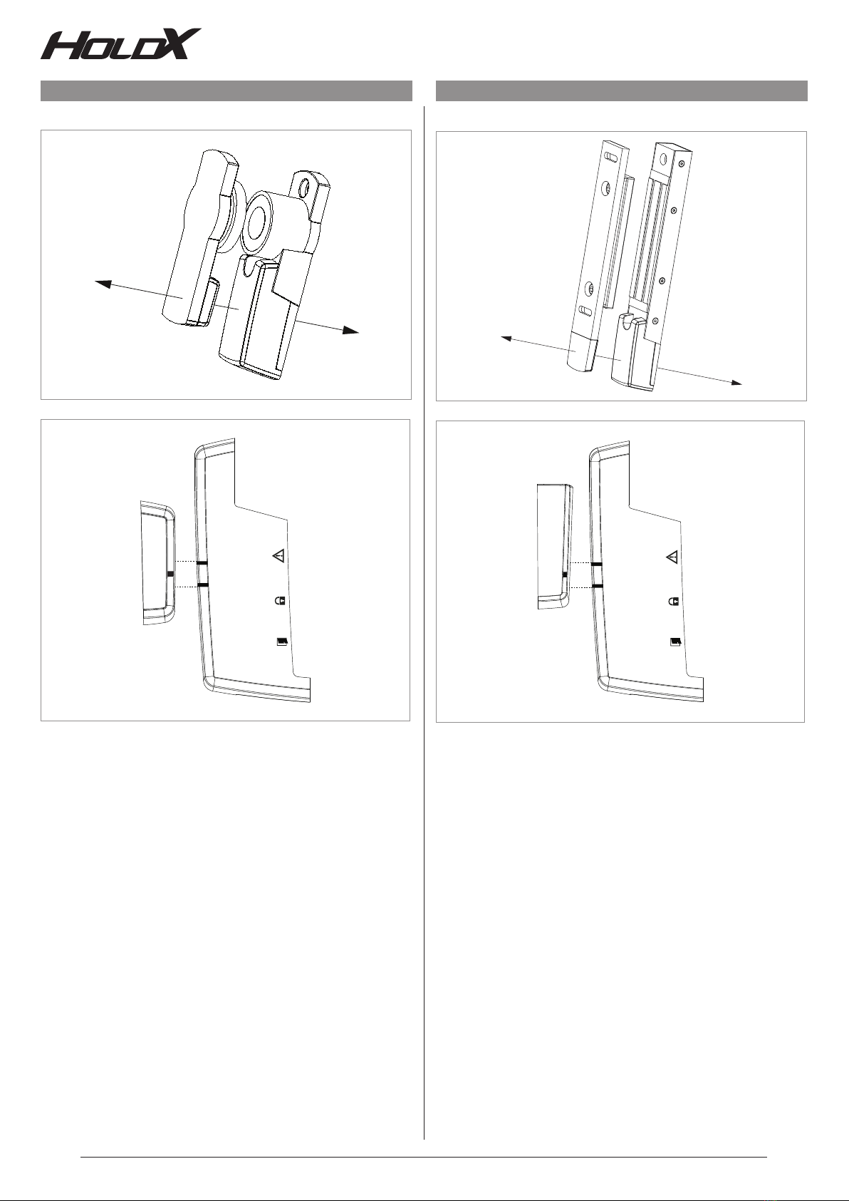
3.3 Anfahrtsrichtungen und Ausrichtung
Abb. 3: HOLDX RS1/2 mit Ankerplatte RS-A1/A2 Abb. 4: HOLDX RL1/2 mit Ankerplatte RL-A1/A2

DE 5
3.4 Montage der Ankerplatten HOLDX RL-A1/A2
Abb. 5: Montage an Drehflügeltüren:Ankerplatte an Monta-
geplatte anbringen und Schrauben M6 x 8 mmTorx festziehen.
Abb. 6: Montageplatte mitAnkerplatte am Profil anbringen
und zur Prozesszuhaltung ausrichten. Schrauben M8 x 12
mm Torx festziehen.
Abb. 7: Montage an Schiebetüren:Ankerplatte am Profil der
Schiebetüre anbringen und zur Prozesszuhaltung ausrichten.
Schrauben M6 x 10 mm Torx festziehen.
3.5 Montage der Ankerplatten HOLDX RS-A1/A2
Abb. 8: Montage an Drehflügeltüren:Ankerplatte an Monta-
geplatte anbringen und Schrauben M6 x 8 mmTorx festziehen.
Abb. 9: Montageplatte mitAnkerplatte am Profil anbringen
und zur Prozesszuhaltung ausrichten.Schrauben M8x12mm
Torx festziehen.
Abb.10: Montage an Schiebetüren:Ankerplatte am Profil der
Schiebetüre anbringen und zur Prozesszuhaltung ausrichten.
Schrauben M6 x 10 mm Torx festziehen.
Alle verwendeten Schrauben sind Linsenkopfschrauben Torx mit versenktem Pin (Sicherheitsschrauben) der Festigkeitsklasse A2/70 und werden mit 6 Nm festgezogen. Lösungssicherung
mit mittelfester Schraubensicherung, wie z.B. Loctite 243.
This manual suits for next models
3
Table of contents
Languages:
Other SSP Construction Equipment manuals


