POWERTEX PBC-S1 User manual

1
POWERTEX
Beam Clamp PBC-S1
GB Instruconforuse
ES Instruccionesdeuso
User Manual
UMPBC20190520ES
!

2
Read through these user instructions carefully before using the beam
clamp. Improper operation may lead to hazardous situations!
The POWERTEX beam clamp is designed for mounting on the lower
ange of an I-beam for suspending a load or lifting device. The beam
clamp is xed in position with a right-hand and left-hand threaded rod
in a scissor construction.
Safety rules
• The beam on which the clamp is to be mounted must be checked
by a competent person. This person must assess the beam’s load
bearing capacity and xings and its suitability for the purpose.
• Check the beam clamp before use for function and any cracking,
deformation or wear.
• Load on the beam clamp must not exceed the maximum load indi-
cated on the rating plate.
• The beam clamp must only be used for beams with a ange width
within the range indicated on the rating plate.
• The clamp must be xed to the beam above the load’s centre of
gravity.
• Dynamic stresses must be avoided.
• Inclined pulls are not permitted.
• Working temperature: -10°C to +50°C.
Dimensioned sketch
Technical data
Art No Model WLL I beam width rangeA max. B min. B max. C D E F min. F max. G min. H Weight
(ton) (mm) (mm) (kg)
16.02PBCS1010 PBC-S1 180-240 270 183 370 94 4 198 100 154 22 20 3,5
16.02PBCS1020 PBC-S1 280-240 270 183 370 102 6 198 100 154 22 20 4,5
16.02PBCS1030 PBC-S1 390-330 355 243 500 132 8 263 148 219 46 22 9,5
16.02PBCS1050 PBC-S1 590-330 355 243 500 142 10 263 148 219 43 28 11
16.02PBCS1100 PBC-S1 10 90-350 364 269 521 180 12 285 165 239 51 38 16
Safety factor: 4:1
Static test coefcient: WLL x 1,5
Generally according to EN 13155
Mounting
Open the beam clamp by unscrewing the threaded rod with the handle
sufciently to allow the clamp to enclose the beam. Screw up the
beam clamp centrally over the load’s centre of gravity. Make sure the
arms on the beam clamp have a secure grip on the beam ange. (See
dimensioned drawing).
The load or suspension hook on the lifting device must hang centrally
from the bowed centre of the suspension bolt.
Continuous maintenance - lubrication
Bearings and threaded sections and the surface of the suspension bolt
in contact with the load hook must be cleaned and lubricated as ne-
cessary. Periodic checks must normally be carried out yearly to detect
and remedy any faults. Damaged parts must be replaced with original
POWERTEX parts.A set of threaded rods and nuts can be ordered
through your dealer.
Contact your dealer for spare parts in general.
Replacing the threaded rod.
1 Open the beam clamp as far as it will go.
2 Knock the locking pin out of the handle.
3 Completely unscrew the threaded rod.
4 Remove the old nuts by pressing them out of the beam clamp’s
arms. Dismantle and clean the spacers.
5 Mount the new nuts together with the spacers.
6 Oil and screw the new threaded rod into the nuts. Make sure both
threads go in simultaneously.
7 Screw up until the handle can be mounted and lock with the locking
pin.
8 Continue screwing to the desired position.
Instruction Grey Label
To change your new POWERTEX Beam Clamp to Black Line:
If the product should be used in dark environments, add the grey label
on the product’s name plate like this.
The data on the nameplate should ALWAYS be visible, and must NOT
be covered.
If the product is modied in any way, or if it is combined with a
non-compatible product / component, AxInter Lifting Solutions take
no responsibility for the consequences in regard to the safety of the
product
POWERTEX Beam Clamp PBC-S1 1 – 10 ton
Assembly / Instruction for use (GB) (Original instructions)

2 3
Lea con atención estas instrucciones de usuario antes de utilizar la
pinza de anclaje para vigas. ¡Un uso inadecuado puede llevar a situa-
ciones peligrosas!
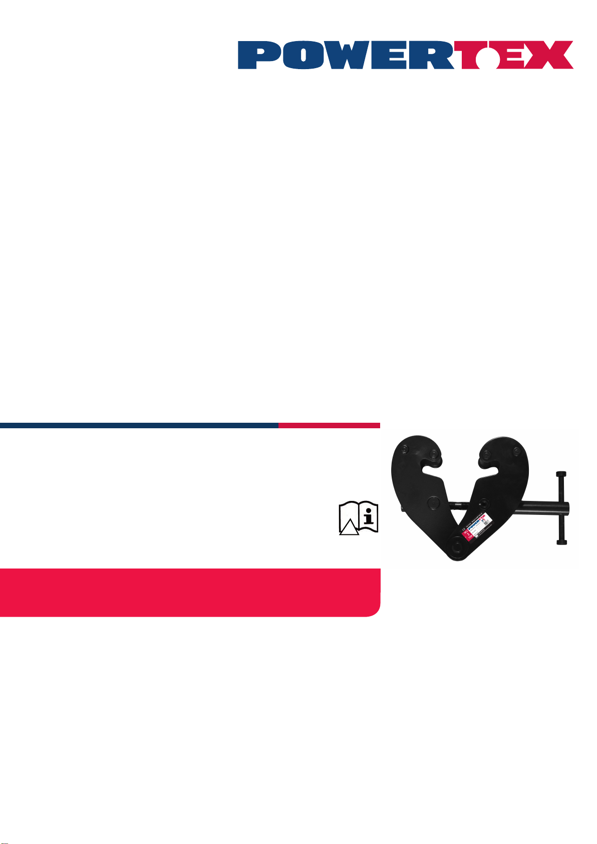
La pinza de anclaje de vigas POWERTEX está diseñada para su
instalación en el borde inferior de una viga en ”I” para la suspensión de
una carga o elevación. La pinza de anclaje se ja mediante una varilla
roscada a derecha e izquierda en una estructura de tijera.
Normas de seguridad
• La viga en la que se va a montar la pinza deber ser vericada por
una persona capacitada. Esta persona debe calcular la capacidad
de soporte del peso de la viga y las jaciones y la idoneidad para su
propósito.
• Compruebe la pinza de anclaje de la viga antes de usar para su
funcionamiento y cualquier fractura, deformación o desgaste.
• La carga en la pinza de anclaje no debe sobrepasar la carga máxi-
ma indicada en la placa de características.
• La pinza de anclaje solo puede utilizarse en vigas con una anchura
de borde dentro del rango indicado en la placa de características.
• La pinza debe jarse a la viga por encima del centro de gravedad
de la carga.
• Se deben evitar las tensiones dinámicas.
• No están permitidas las fuerzas inclinadas.
• Temperatura de trabajo: de -10°C a +50°C.
Esbozo de dimensiones
Esquema dimensionado
Referencia Código WLL Rango de viga A max. B min. B max. C D E F min. F max. G min. H Peso
(ton) (mm) (mm) (kg)
16.02PBCS1010 PBC-S1 180-240 270 183 370 94 4 198 100 154 22 20 3,5
16.02PBCS1020 PBC-S1 280-240 270 183 370 102 6 198 100 154 22 20 4,5
16.02PBCS1030 PBC-S1 390-330 355 243 500 132 8 263 148 219 46 22 9,5
16.02PBCS1050 PBC-S1 590-330 355 243 500 142 10 263 148 219 43 28 11
16.02PBCS1100 PBC-S1 10 90-350 364 269 521 180 12 285 165 239 51 38 16
Factor de seguridad: 4:1
Coeciente de prueba estática: WLL x 1,5
En general según EN 13155
Montaje
Abra la pinza de anclaje desatornillando la varilla roscada con la
palanca lo suciente como para permitir que la pinza abarque la viga.
Atornille la pinza de anclaje de la viga centrada sobre el centro de gra-
vedad de la carga. Asegúrese de que los brazos de la pinza de anclaje
tienen una sujeción segura en el borde de la viga. (Véase esquema
dimensional).
El gancho de carga o suspensión en el equipo de elevación debe
colgar centralmente del centro inclinado del perno de suspensión.
Mantenimiento continuo: engrase
Los rodamientos y secciones roscadas y la supercie del perno de
suspensión en contacto con el gancho de carga deben estar limpios
y engrasados según sea necesario. Se deben realizar revisiones
periódicas anuales para detectar y corregir cualquier fallo. Las piezas
dañadas se deben sustituir por piezas originales POWERTEX. Puede
pedir un kit de varillas roscadas y tuercas a su distribuidor.
Contacte con su distribuidor para los repuestos en general.
Sustitución de la varilla roscada.
1 Abra la pinza de anclaje todo lo que pueda.
2 Retire el pasador de bloqueo fuera de la palanca.
3 Suelte la varilla roscada por completo.
4 Retire las tuercas usadas presionando hacia afuera de los brazos
de la pinza de anclaje. Desmonte y limpie los separadores.
5 Monte las nuevas tuercas con los separadores.
6 Engrase y atornille la nueva varilla roscada en las tuercas. Asegúre-
se de que ambas roscas entran simultáneamente.
7 Atornille hasta que se pueda montar la palanca y bloquear con el
pasador.
8 Continúe atornillando hasta la posición deseada.
Instrucciones Etiqueta Gris
Para cambiar su nueva Pinza de Anclaje de Vigas POWERTEX a la
Línea Negra:
Si el producto se va a utilizar en ambientes oscuros, coloque la etique-
ta gris en la placa identicativa del producto.
Los datos de la placa identicativa deben ser visibles SIEMPRE y NO
se deben cubrir.
Si se modica el producto de alguna manera, o si se combina con un
producto / componente no compatible, el AxInter Lifting Solutions no
tendrá ninguna responsabilidad sobre las consecuencias a efectos de
seguridad del producto.
Pinza de Anclaje de Vigas POWERTEX PBC-S1 1 – 10 ton
Montaje / Instrucciones de uso (ES)

4
Product compliance and conformity
SCM Citra OY
Juvan Teollisuuskatui 25 C
02920 Espoo
Finland
www.powertex-products.com

45
CERTEX Lifting KnowHow app
Download The Lifting KnowHow app’en from the App Store / Google play!
The App has the following features:
- Load charts for different types of lifting slings
- Protractor for measuring sling angles
- Instructions for safe use of a selection of lifting gear
- Built-in gps function that nds the Lifting Solutions Group ofce closest to
your position.
- And a lot more.
The Lifting KnowHow is a unique knowledge transfer programme.
CertMax+
The CertMax+ system is a unique leading edge certication management
system which is ideal for managing a single asset or large equipment port-
folio across multiple sites. Designed by the Lifting Solutions Group, to deliver
optimum asset integrity, quality assurance and traceability, the system also
improves safety and risk management levels.
User Manuals
You can always nd the valid and updated User Manuals on the web.
The manual is updated continuously and valid only in the latest version.
NB! The English version is the Original instruction.
The manual is available as a download under the following link:
www.powertex-products.com/manuals
!

www.powertex-products.com
Canary Islands
Table of contents
Languages:
Other POWERTEX Power Tools manuals
Popular Power Tools manuals by other brands

Electronica Technologies
Electronica Technologies EL700 manual

Power Glide
Power Glide 60101211 Assembly and operating instructions

RED ROOSTER
RED ROOSTER RRI-BS6 manual

Baileigh Industrial
Baileigh Industrial DP-1000VS Operator's manual

Steel City
Steel City 30-200 owner's manual

EINHELL
EINHELL 44.651.50 Original operating instructions