POWERTEX PBC-S1 User manual

POWERTEX
Beam Clamp PBC-S1
GB Instruconforuse
DE Bedienungsanleitung
User Manual
UMPBC20200914DE
!

2
Read through these user instructions carefully before using the beam
clamp. Improper operation may lead to hazardous situations!
The POWERTEX beam clamp is designed for mounting on the lower
ange of an I-beam for suspending a load or lifting device. The beam
clamp is xed in position with a right-hand and left-hand threaded rod
in a scissor construction.
Safety rules
• The beam on which the clamp is to be mounted must be checked
by a competent person. This person must assess the beam’s load
bearing capacity and xings and its suitability for the purpose.
• Check the beam clamp before use for function and any cracking,
deformation or wear.
• Load on the beam clamp must not exceed the maximum load indi-
cated on the rating plate.
• The beam clamp must only be used for beams with a ange width
within the range indicated on the rating plate.
• The clamp must be xed to the beam above the load’s centre of
gravity.
• Dynamic stresses must be avoided.
• Inclined pulls are not permitted.
• Working temperature: -10°C to +50°C.
Dimensioned sketch
Technical data
Art No Model WLL I beam width rangeA max. B min. B max. C D E F min. F max. G min. H Weight
(ton) (mm) (mm) (kg)
16.02PBCS1010 PBC-S1 180-240 270 183 370 94 4 198 100 154 22 20 3,5
16.02PBCS1020 PBC-S1 280-240 270 183 370 102 6 198 100 154 22 20 4,5
16.02PBCS1030 PBC-S1 390-330 355 243 500 132 8 263 148 219 46 22 9,5
16.02PBCS1050 PBC-S1 5 90-330 355 243 500 142 10 263 148 219 43 28 11
16.02PBCS1100 PBC-S1 10 90-350 364 269 521 180 12 285 165 239 51 38 16
Safety factor: 4:1
Static test coefcient: WLL x 2
Generally according to EN 13155
Mounting
Open the beam clamp by unscrewing the threaded rod with the handle
sufciently to allow the clamp to enclose the beam. Screw up the
beam clamp centrally over the load’s centre of gravity. Make sure the
arms on the beam clamp have a secure grip on the beam ange. (See
dimensioned drawing).
The load or suspension hook on the lifting device must hang centrally
from the bowed centre of the suspension bolt.
Continuous maintenance - lubrication
Bearings and threaded sections and the surface of the suspension bolt
in contact with the load hook must be cleaned and lubricated as ne-
cessary. Periodic checks must normally be carried out yearly to detect
and remedy any faults. Damaged parts must be replaced with original
POWERTEX parts.A set of threaded rods and nuts can be ordered
through your dealer.
Contact your dealer for spare parts in general.
Replacing the threaded rod.
1 Open the beam clamp as far as it will go.
2 Knock the locking pin out of the handle.
3 Completely unscrew the threaded rod.
4 Remove the old nuts by pressing them out of the beam clamp’s
arms. Dismantle and clean the spacers.
5 Mount the new nuts together with the spacers.
6 Oil and screw the new threaded rod into the nuts. Make sure both
threads go in simultaneously.
7 Screw up until the handle can be mounted and lock with the locking
pin.
8 Continue screwing to the desired position.
Instruction Grey Label
To change your new POWERTEX Beam Clamp to Black Line:
If the product should be used in dark environments, add the grey label
on the product’s name plate like this.
The data on the nameplate should ALWAYS be visible, and must NOT
be covered.
If the product is modied in any way, or if it is combined with a
non-compatible product / component, AxInter Lifting Solutions take
no responsibility for the consequences in regard to the safety of the
product
POWERTEX Beam Clamp PBC-S1 1 – 10 ton
Assembly / Instruction for use (GB) (Original instructions)

2 3
Lesen Sie diese Bedienungsanleitung aufmerksam durch bevor Sie die
Balkenklemme in Betrieb nehmen. Unsachgemäße Verwendung kann
Gefahren hervorrufen!
Die POWERTEX Balkenklemme wird zum Aufhängen von Lasten oder
einer Hebevorrichtung am unteren Flansch eines I-Balken montiert.
Sie wird mit Hilfe einer Stange mit Rechts- und Linksgewinde in einer
Scherenkonstruktion festgespannt.
Sicherheitsanweisungen
• Der Balken, an dem die Balkenklemme montiert werden soll, muss
zuvor von einem Fachmann überprüft werden. Dieser soll die Trag-
fähigkeit und Halterungen des Balkens beurteilen und dessen Eignung
für diesen Zweck einschätzen.
• Führen Sie vor der Verwendung der Balkenklemme eine Funktions-
kontrolle durch und überprüfen Sie die Klemme auf eventuelle Risse,
Deformation und Verschleiß.
• Die Belastung der Balkenklemme darf die auf dem Typenschild
angegebene, zulässige max. Last nicht überschreiten.
• Die Balkenklemme darf nur an Balken mit einer Flanschbreite
montiert werden, die dem auf dem Typenschild angegebenen Bereich
entspricht.
• Die Klemme muss am Balken mittig über dem Schwerpunkt der
Last angebracht werden.
• Dynamische Beanspruchungen sind zu vermeiden.
• Schiefbelastung ist nicht zulässig.
• Arbeitstemperatur: -10°C to +50°C.
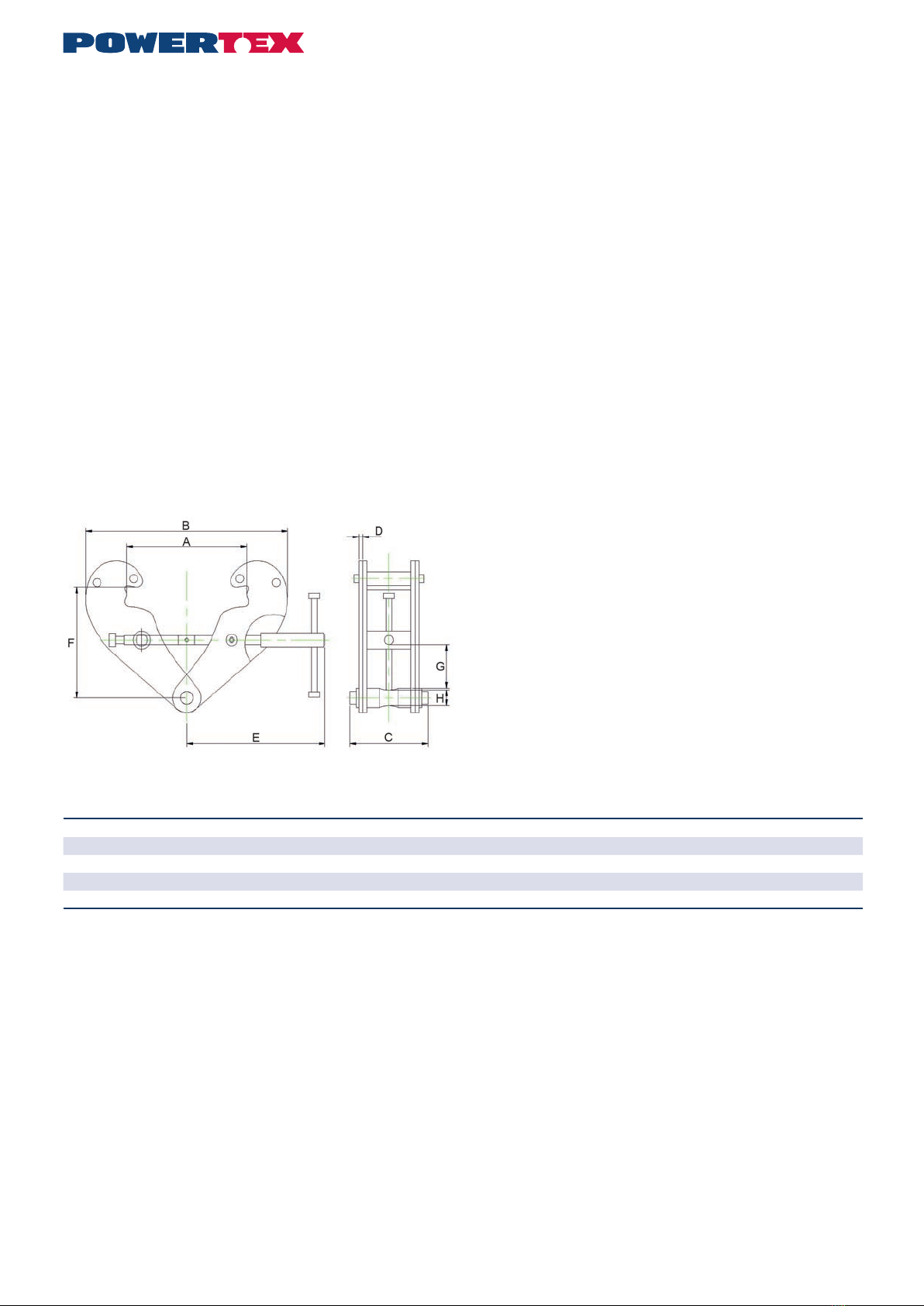
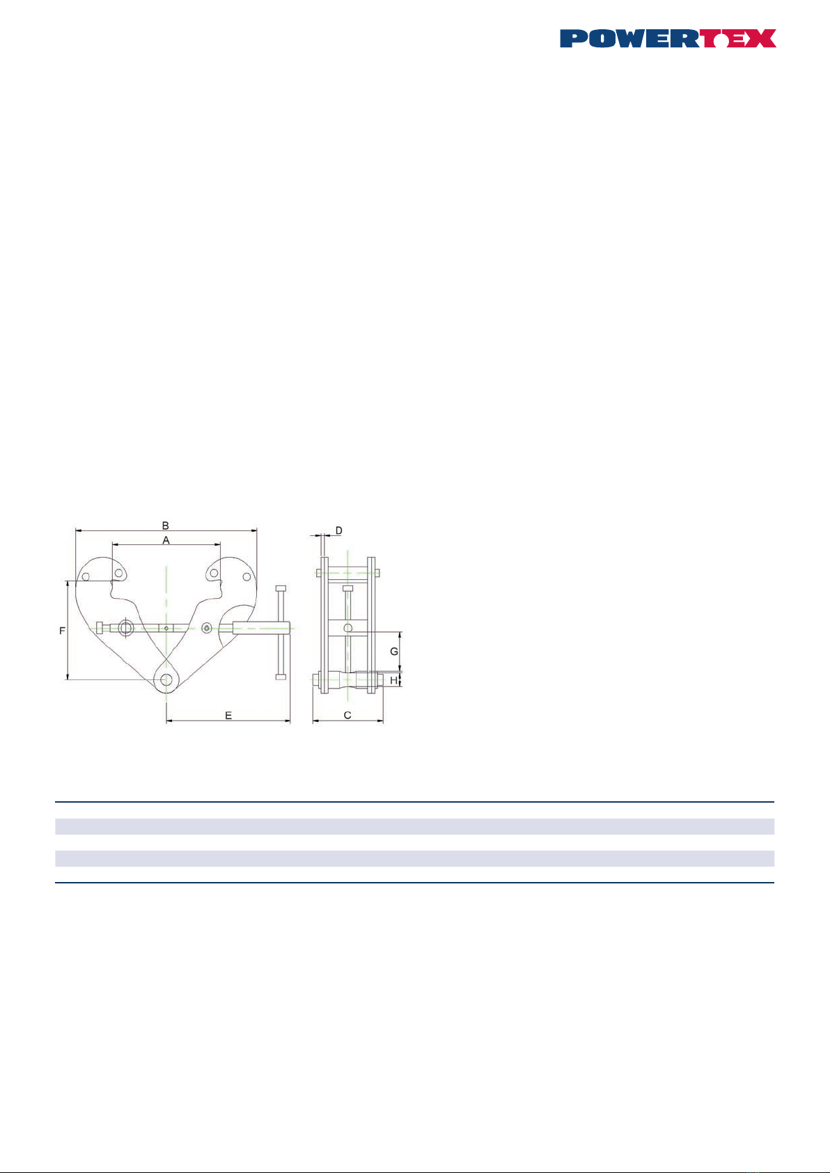
Maßskizze
Technische Daten
Art. Nr. Modell WLL ton Greifbereich A max. B min. B max. C D E F min. F max. G min. H Gewicht
(mm) (mm) (kg)
16.02PBCS1010 PBC-S1 180-240 270 183 370 94 4 198 100 154 22 20 3,5
16.02PBCS1020 PBC-S1 280-240 270 183 370 102 6 198 100 154 22 20 4,5
16.02PBCS1030 PBC-S1 390-330 355 243 500 132 8 263 148 219 46 22 9,5
16.02PBCS1050 PBC-S1 5 90-330 355 243 500 142 10 263 148 219 43 28 11
16.02PBCS1100 PBC-S1 10 90-350 364 269 521 180 12 285 165 239 51 38 16
Sicherheitsfaktor: 4:1.
Statischer Prüfungskoefzient: WLL x 2.
Im Allgemeinen gemäß EN 13155.
Montage
Die Balkenklemme wird durch Herausschrauben der Gewindestange
mit dem Griff geöffnet, und zwar so weit, dass die Klemme am Balken
angebracht werden kann. Sie wird mittig über dem Schwerpunkt der
Last angeschraubt. Prüfen Sie, dass die Arme der Balkenklemme
sicher um den Balkenansch greifen. (Siehe Maßzeichnung).
Die Last oder der Aufhängehaken der Hebevorrichtung müssen mittig
am vertieften Zentrum des Aufhängebügels hängen.
Fortlaufende Wartung - Schmierung
Die Lager und die Gewindestange, sowie die Kontaktäche des
Aufhängebügels zum Lastenhaken müssen bei Bedarf gereinigt und
geschmiert werden. Eine regelmäßige Überprüfung wird im Normalfall
1x jährlich durchgeführt, um eventuelle Mängel zu entdecken und zu
beseitigen. Beschädigte Teile sind durch Originalteile von POWERTEX
zu ersetzen. Ein Satz bestehend aus Gewindestange und Muttern
kann über den örtlichen Fachhandel bestellt werden.
Wenden Sie sich für Ersatzteile im Allgemeinen an Ihren Händler.
Austausch der Gewindestange.
1 Balkenklemme so weit wie möglich öffnen.
2 Sicherungszapfen aus dem Griff klopfen.
3 Gewindestange vollständig herausschrauben.
4 Die alten Muttern durch Herausdrücken aus den Armen der Balkenk-
lemme entfernen. Demontieren und Distanzhülsen reinigen.
5 Die neuen Muttern zusammen mit den Distanzhülsen montieren.
6 Die neue Gewindestange einölen und in die Muttern schrauben.
Überprüfen Sie, dass beide Gewinde gleichzeitig greifen.
7 Festschrauben, sodass der Griff montiert werden kann und mit
Sicherungszapfen sichern.
8 Auf gewünschte Position schrauben.
Anweisungen graues Etikett
Für den Wechsel Ihrer neuen POWERTEX Trägerklemme zur Black
Line:
Falls das Produkt in einem dunklen Umfeld verwendet wird, fügen Sie
das graue Etikett auf dem Typschild hinzu (wie hier gezeigt).
Die Daten auf dem Typschild müssen IMMER lesbar sein und dürfen
NICHT verdeckt werden.
Falls das Produkt auf irgendeine Weise modiziert wird oder in
Kombination mit nicht kompatiblen Produkten/Bauteilen verwendet
wird, übernimmt die AxInter Lifting Solutions keine Haftung für Folgen
hinsichtlich der Sicherheit des Produktes.
POWERTEX Balkenklemme PBC-S1 1 – 10 ton
Montage / Bedienungsanleitung (DE)

4
Product compliance and conformity
SCM Citra OY
Juvan Teollisuuskatui 25 C
02920 Espoo
Finland
www.powertex-products.com

45
CertMax+
The CertMax+ system is a unique leading edge certication management
system which is ideal for managing a single asset or large equipment port-
folio across multiple sites. Designed by the Lifting Solutions Group, to deliver
optimum asset integrity, quality assurance and traceability, the system also
improves safety and risk management levels.
User Manuals
You can always nd the valid and updated User Manuals on the web.
The manual is updated continuously and valid only in the latest version.
NB! The English version is the Original instruction.
The manual is available as a download under the following link:
www.powertex-products.com/manuals
!

www.powertex-products.com
Canary Islands
Canary Islands
Table of contents
Languages:
Other POWERTEX Power Tools manuals
Popular Power Tools manuals by other brands

Electronica Technologies
Electronica Technologies EL700 manual

Power Glide
Power Glide 60101211 Assembly and operating instructions

RED ROOSTER
RED ROOSTER RRI-BS6 manual

Baileigh Industrial
Baileigh Industrial DP-1000VS Operator's manual

Steel City
Steel City 30-200 owner's manual

EINHELL
EINHELL 44.651.50 Original operating instructions