Powervault G200 User manual

1
Cover
G200
INSTALLATION
MANUAL
WINNER:
Innovator of the Year
Solar Innovation of the Year
2
Safety
Case: The case is essential to ensure
the safety of the device. Do not open
unless qualified. If the case becomes
damaged contact an authorised
Powervault engineer. The Powervault
unit weighs 50kg and should be
handled with appropriate lifting
techniques and pallet trucks, if
required.
Location: It is essential Powervault
G200 is installed in an appropriate
location according to its Technical and
Environmental specifications (see
Technical Specifications document)
with at least 10cm of space behind the
unit to allow for appropriate ventilation.
Installation: The installation of
Powervault G200 must only be
undertaken by approved Powervault
installers/qualified electricians.
Batteries: This equipment is heavy
and contains potentially hazardous
voltages that may cause personal
injury if handled incorrectly. This
equipment must be installed and
serviced only by qualified electrical
service personnel. The batteries
should be disposed of or recycled
according to your local code of
conduct.
Only use batteries supplied or
approved by Powervault. Do not mix
and match Li-Ion and Lead Acid
batteries in a unit. These actions will
result in loss of warranty on the
equipment.
ELECTRONIC DEVICE:
DO NOT THROW AWAY
Proper disposal of device and batteries is required.
Please refer to our website for details on how to recycle and replace
your batteries. www.powervault.co.uk/recycling

3
Register your Powervault G200
Log-in to your Powervault Installer Portal to register your customer’s
Powervault, place the Powervault under Warranty and automatically set-up
your customer on their Powervault Customer Portal:
portal.powervault.co.uk
Download the warranty terms
Remember! The Warranty is only valid when your customer’s Powervault has
been registered via your Powervault Installer Portal and is connected to the
internet either via the Wi-Fi adaptor or Ethernet cable:
www.powervault.co.uk/warranty
Product List
2.0 2.54.0
6.0
3.04.0
2.0 2.5
4.0
6.03.04.0
2.0 2.5
4.0
6.03.04.0
2.0 2.5
4.0
6.03.04.0
2.0
2.54.06.03.04.0
2.0
2.5
4.06.03.04.0
2.0 2.54.06.0
3.0
4.0
Lithium-ion Lead Acid (Tubular Gel) Lead Acid (AGM) Powervault overview 4
Part 1: Wiring 5
Part 2: Preparing the Powervault 8
Part 3: Emergency Power Socket 9
Part 4: Loading batteries
Option A: Lead Acid batteries 12
Option B: Lithium-ion cells 14
Part 5: Replacing the Powervault G200 panels 17
Part 6: Connecting the current clamp 18
Part 7: Connecting the Powervault G200 to the internet 20
Part 8: Registering your customer’s Powervault G200 21
Part 9: Commissioning 23
Record your serial numbers 25
Contents

4
Powervault overview
Parts included with
your delivery:
Powervault G200
Lithium-ion battery packs / Lead Acid
batteries (amount and type dependent
on product purchased)
Accessory Box
Current (CT) clamp
Current clamp extension cable
Battery connectors
Powervault G200 User Manual
Powervault G200 Technical Specification
Powervault G200 Installation Manual
Parts not included with
your delivery:
7A/10A fused spur (fuse size dependent
on Powervault type)
Rotary isolator
Associated wiring
Wi-Fi nano-router

5
ELECTRICAL SAFETY
To reduce the risk of fire, connect only to a circuit
provided with a 7A / 10A maximum branch circuit
overcurrent protection in accordance with BS1362.
Do not work alone under hazardous conditions.
Check that the power cord(s), plug(s), and sockets
are in good condition.
To reduce the risk of electric shock, disconnect
the equipment from the AC power outlet before
installing or connecting to other equipment.
Reconnect after all electrical connections are made.
Use one hand, whenever possible, to connect or
disconnect signal cables to avoid a possible shock
from touching two surfaces with different
electrical grounds.
Connect the equipment to a three wire AC connection
(live, neutral and ground). The unit must be connected
to appropriate branch circuit/mains protection
(fuse or circuit breaker). Connection to any other
type of connection may result in a shock hazard.
In order to maintain compliance with the EMC
directive, wires attached to the Powervault
should not exceed 25 meters in length.
• Prepare the electrical wiring according to figure 1 or figure 2. All wiring to be perform in strict accordance with
local building regulations.
• The ideal installation will feature a separate RCBO block splitting from the Henley Block as shown in figure 1.
• If this is not possible connecting to consumer unit is acceptable as long as it is on a dedicated 16A RCBO can be
inserted into the unit as shown in figure 2.
• The rotary isolator will need to be installed directly downstream of the dedicated RCBO.
• If a power socket needs to be added for the Powervault internet connection then the additional power socket
should be installed downstream of the rotary isolator as shown in figure 1.
• The fused spur should be rated according to table 1.
TABLE 1
Unit Fused Spur Rating (amps)
3kWh Lead Acid (AGM Gel) 7
4kWh Lead Acid (AGM Gel) 7
2.5kWh Lead Acid (Tubular Gel) 10
4.0kWh Lead Acid (Tubular Gel) 10
2kWh Lithium-ion 10
4kWh Lithium-ion 10
6kWh Lithium-ion 10
Part 1: Wiring

6
25m maximum wiring distance
Live
Neutral
Solar inverter
Solar panels Electricity supply mete
r
Grid supply
Current
clamp
Henley Block connection
RCBO Consumer Unit Not included,
dedicated for Powervault
Not included
Additional power socket if
required for nano-router
Rotary
Isolator
RCBO
7A / 10A
fused spur
Powervault
Wi-Fi/internet
Household ring main
Installation schematic
Current clamp with
arrow indication
FIGURE 1
Recommended Installation

7
25m maximum wiring distance
Neutral
Solar inverter
Solar panels
Electricity supply mete
r
Grid supply
Henley Block connection
RCBO Consumer Unit
Not included, dedicated for Powervault
Not included
Additional power socket if
required for nano-router
Rotary
Isolator
7A / 10A
fused spur
Powervault
Wi-Fi/internet
Household ring main
w/ Dedicated RCBO
for the Powervault
Current
clamp
Installation schematic
FIGURE 2
Possible Installation (Check with local regulations)
Current clamp with
arrow indication
8
i
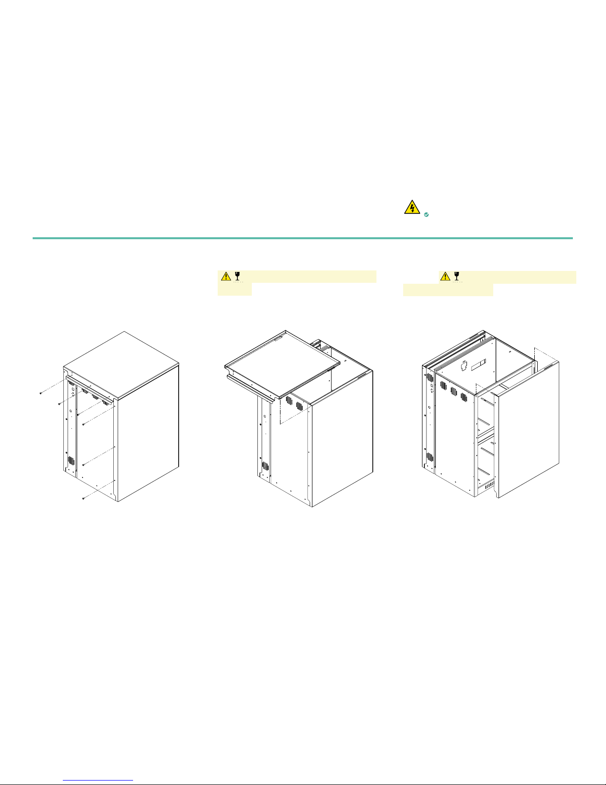
Remove 6 screws to the top and left side panel.
Keep the screws in a safe place.
ii
Slide the top panel backwards and lift carefully
Caution: delicate wiring connected to the
top cover. Disconnect the earth connection and
place the panel in a safe place for the duration of
the battery pack installation.
iii
Carefully lift the left-hand side panel and slide
outwards. Caution: delicate wiring connected
to the left-hand side panel. Disconnect the earth
connection and place the panel in a safe place for
the duration of the battery pack installation.
A A
B B
C C
D D
E E
F F
8
8
7
7
6
6
5
5
4
4
3
3
2
2
1
1
DRAWN
CHK'D
UNLESS OTHERWISE SPECIFIED:
DIMENSIONS ARE IN MILLIMETERS
SURFACE FINISH:
TOLERANCES:
LINEAR: +/- 0.05
ANGULAR: +/- 0.5
FINISH:
DEBURR AND
BREAK SHARP
EDGES
NAME
SIGNATURE
DATE
MATERIAL:
DO NOT SCALE DRAWING
REVISION
TITLE:
DWG NO.
SCALE:1:20
SHEET 1 OF 5
A3
MATERIAL THICKNESS:
C. Tyler
A. Locke
10/05/17
10/05/17
Dynamic Marine Engineering
PV1_A00_8_Full 500 Assembly
Full 500 Assembly
1
mm
A A
B B
C C
D D
E E
F F
8
8
7
7
6
6
5
5
4
4
3
3
2
2
1
1
DRAWN
CHK'D
UNLESS OTHERWISE SPECIFIED:
DIMENSIONS ARE IN MILLIMETERS
SURFACE FINISH:
TOLERANCES:
LINEAR: +/- 0.05
ANGULAR: +/- 0.5
FINISH:
DEBURR AND
BREAK SHARP
EDGES
NAME
SIGNATURE
DATE
MATERIAL:
DO NOT SCALE DRAWING
REVISION
TITLE:
DWG NO.
SCALE:1:20
SHEET 2 OF 5
A3
MATERIAL THICKNESS:
C. Tyler
A. Locke
10/05/17
10/05/17
Dynamic Marine Engineering
PV1_A00_8_Full 500 Assembly
Full 500 Assembly
1
mm
A A
B B
C C
D D
E E
F F
8
8
7
7
6
6
5
5
4
4
3
3
2
2
1
1
DRAWN
CHK'D
UNLESS OTHERWISE SPECIFIED:
DIMENSIONS ARE IN MILLIMETERS
SURFACE FINISH:
TOLERANCES:
LINEAR: +/- 0.05
ANGULAR: +/- 0.5
FINISH:
DEBURR AND
BREAK SHARP
EDGES
NAME
SIGNATURE
DATE
MATERIAL:
DO NOT SCALE DRAWING
REVISION
TITLE:
DWG NO.
SCALE:1:20
SHEET 3 OF 5
A3
MATERIAL THICKNESS:
C. Tyler
A. Locke
10/05/17
10/05/17
Dynamic Marine Engineering
PV1_A00_8_Full 500 Assembly
Full 500 Assembly
1
mm
Part 2: Preparing the Powervault
ELECTRICAL SAFETY
Ensure the Powervault G200 is completely
isolated from the mains supply.
FIGURE 3 FIGURE 4 FIGURE 5

9
i
Ensure the Powervault G200 is completely isolated
from the mains supply and from the rotary isolator.
Follow local lock-out tag-out procedures
ii
If installation of emergency power socket (EPS) is
taking place after battery installation see Part 2 for
panel removal. Remove 3 screws on the right side
panel as shown in figure 6.
iii
Slide right side panel up and lift carefully (figure 7)
Caution: delicate wiring connected to the top
cover. Disconnect the earth connection and place
the panel in a safe place for the duration of the EPS
installation.
Powervault’s Emergency Power Socket (EPS) is not fitted as standard and Installers are therefore
occasionally required to fit this accessory to the Powervault if the customer has ordered it. The EPS gives
customers access to power available in the batteries during black outs; the EPS will be able to power basic
electrical appliances, provided the batteries have energy stored in them at the time, during emergencies and
when there is grid failure.
Part 3: Emergency Power Socket (if purchased)
ELECTRICAL SAFETY
Ensure the Powervault G200 is completely
isolated from the mains supply.
FIGURE 6 FIGURE 7
A A
B B
C C
D D
E E
F F
8
8
7
7
6
6
5
5
4
4
3
3
2
2
1
1
PV1_A03_8_500 Assembly Remove Side and Cover
A A
B B
C C
D D
E E
F F
8
8
7
7
6
6
5
5
4
4
3
3
2
2
1
1
PV1_A03_8_500 Assembly Remove Side and Cover

10
v
Remove the EPS from its box and identify the enclosed
metal bracket (x1), nuts (x2), and washers (x2).
vi
Using the metal bracket, 4 x nuts and 4 x washers,
secure the EPS on the Powervault G200 further by
placing the bracket around the EPS but under the
wiring and fixing the washers and nuts onto the
two screws located above and beneath the EPS on
the Powervault G200 casing. See figure 9.
iv
Facing the front of the Powervault G200, locate
the plastic cover for the EPS in the bottom-right
corner. Remove the cap by pushing it firmly
outwards from inside the unit. See figure 8.
A
DETAIL A
SCALE 2 : 5
A A
B B
C C
D D
E E
F F
8
8
7
7
6
6
5
5
4
4
3
3
2
2
1
1
PV1_A01_8_500 Assembly with Socket
FIGURE 8
FIGURE 9
A A
B B
C C
D D
E E
F F
8
8
7
7
6
6
5
5
4
4
3
3
2
2
1
1
PV1_A03_8_500 Assembly Remove Side and Cover
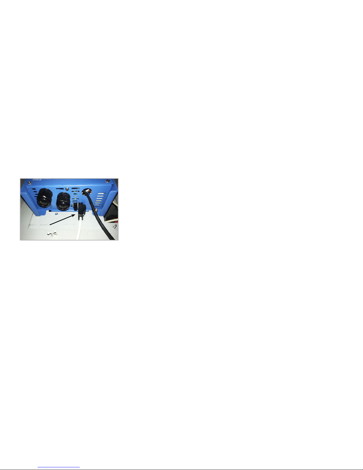
11
vii
Plug the AC-out power cable into the bottom of the
inverter.
viii
Reinstall right side earth wire to panel, attach panel
to unit and reinstall screws see (if finished reinstall
earth wire to top and reinstall screws).
12
Part 4: Loading batteries
ELECTRICAL SAFETY
Ensure the Powervault G200 is completely
isolated from the mains supply.
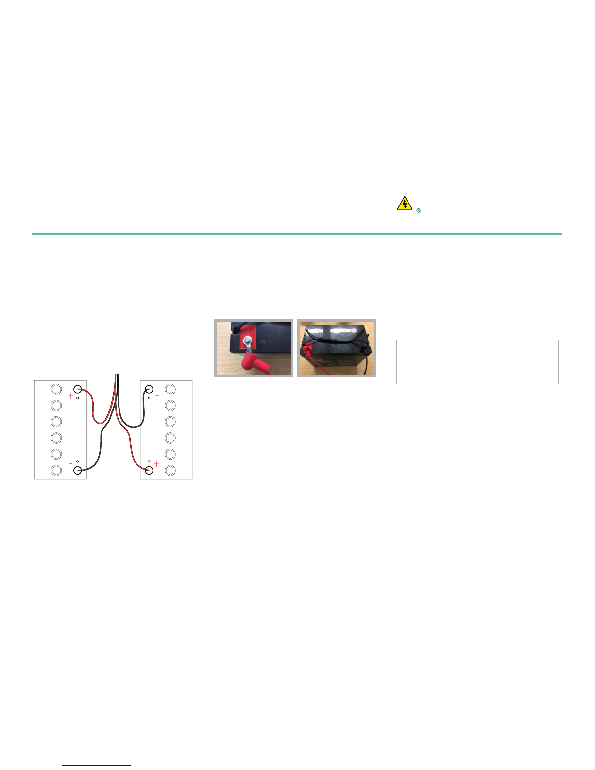
i
Connect the battery cables to the batteries prior to
the loading the batteries into the unit. Connect the
RED cable to the positive terminal and the BLACK
cable to the negative terminal using a socket wrench.
ii
Place the battery terminal covers over the terminals.
iii
Remove screws from top tray to allow for 2nd row
of batteries to slide in place. Keep the screws in a
safe place for re-installation.
Option A:
Loading Lead Acid batteries
Lead Acid Unit
+
-
+
-
Power Connection
To Powervault
Cables Supplied as Part of Accessory Box
Connect Red to positive and Black to Negative
Note: 2 Batteries must be connected on any shelf
Connection Detail 2 Batteries Per Shelf
Cables supplied as part of accessory box
connect RED to positive and BLACK to negative
Power connection
to Powervault
Note: Two batteries should be plugged into the
socket on each level. The unit will not work if
only one battery is plugged into a socket.
FIGURE 10
13
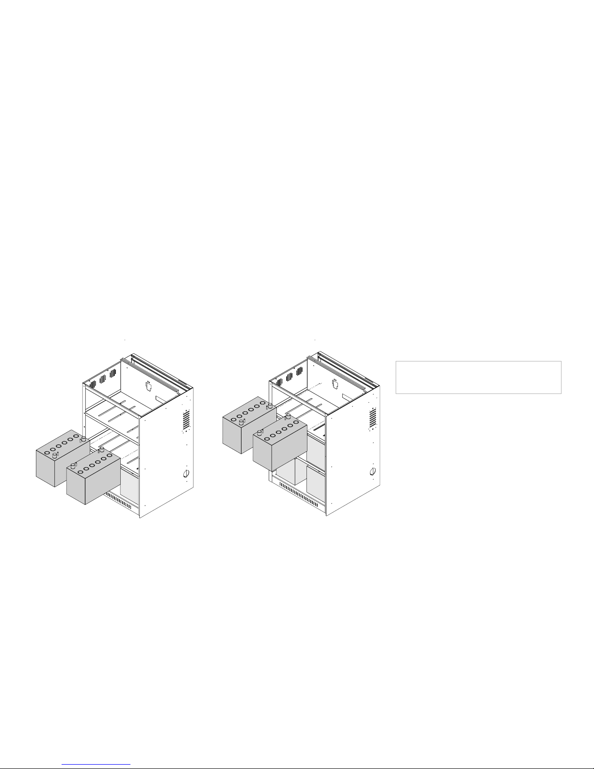
iv
Place the lead acid batteries onto each shelf as shown
in figure11 and 12. For the 3kWh unit place 4 total
batteries. For the 4kWh unit place 6 total batteries.
v
Plug the battery leads into the connectors inside the
Powervault. Insert the plastic end into the Powervault
unit placing the connections on top of each other.
Each connector should click into place. This will be
the case on each shelf.
A A
B B
C C
D D
E E
F F
8
8
7
7
6
6
5
5
4
4
3
3
2
2
1
1
PV1_A00_8_Full 500 Assembly with Batteries
A A
B B
C C
D D
E E
F F
8
8
7
7
6
6
5
5
4
4
3
3
2
2
1
1
PV1_A00_8_Full 500 Assembly with Batteries
FIGURE 11
Battery installation for 3kWh & 4kWh units.
FIGURE 12
Battery installation for 4kWh units only.
Note: The powervault will not function properly if
only 1 battery is plugged in per shelf.
14
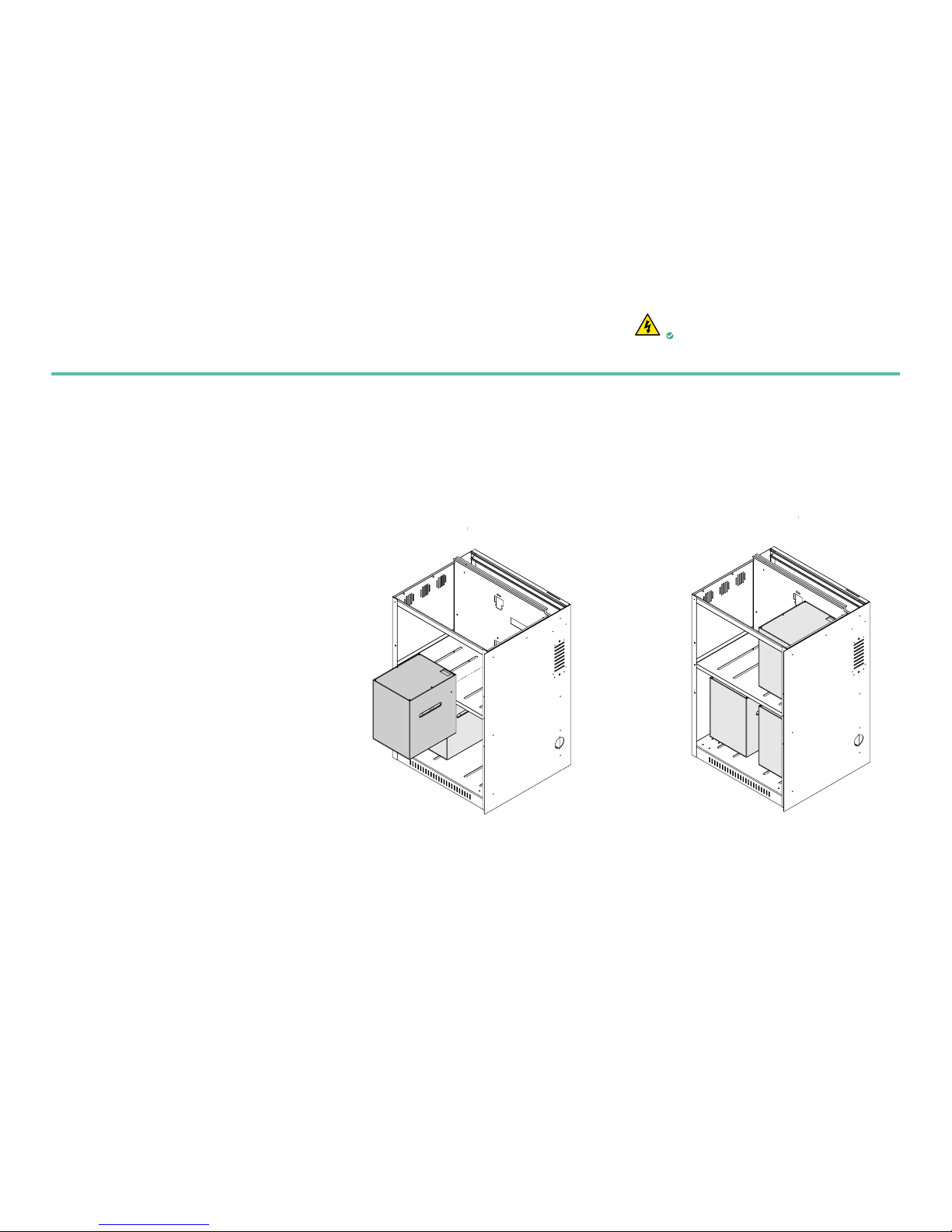
FIGURE 13
4kWh Li-Ion Unit
FIGURE 14
6kWh Li-Ion Unit
Part 4: Loading batteries
ELECTRICAL SAFETY
Ensure the Powervault G200 is completely
isolated from the mains supply.
i
Unpack Li-ion batteries. Record the battery 5 digit
serial numbers on the back page of this manual. It
will be needed for registration later.
ii
For the 4kWh unit place 2 batteries as shown in
figure 13. (One battery per shelf).
iii
For the 6kWh unit place 3 batteries as shown in
figure 14. (Two batteries on the bottom shelf and
one on top shelf).
Option B:
Loading Lithium-ion cells
A A
B B
C C
D D
E E
F F
8
8
7
7
6
6
5
5
4
4
3
3
2
2
1
1
PV1_A00_8_Full 500 Assembly with Li - Ion Batteries
A A
B B
C C
D D
E E
F F
8
8
7
7
6
6
5
5
4
4
3
3
2
2
1
1
PV1_A00_8_Full 500 Assembly with Li - Ion Batteries

15
FIGURE 15
FIGURE 16
iv
Connect the power leads provided in the accessory
box to the battery. In the case of a 2 or 4kWh unit
the 4 wire connection piece will plug into the wall
of the Powervault while both of the 2 cable power
leads should plug into the battery See figure 15.
v
The 6kWh unit will require that the power leads be
split into the two battery packs on the lower shelf.
See figure 16.
Battery power cables Data cable connection
5 Digit Serial Number
Required for
commissioning of unit and
connecting to the portal
Data Jump Connection
Part of Accessory Box
Data connection
Left side in
Right side out
Power connections to Powervault
Part of Accessory Box
Data connection to Powervault
Hard wired into Powervault Unit

16
vi
Connect the data cable that is hardwired into the
Powervault unit to the right hand side of the data
connection see figure 17.
vii
The 6kWh unit will require that the lower shelf
have the batteries connected together via a data
cable see figure 16.
Note: The batteries will charge faster if all 4
power wires are connected into a battery which
is why this is recommended for the top shelf
and on the 4kWh unit.
Note: If the data connection is not made with all
of the batteries the Powervault will not
function.
5 Digit Serial Number
Required for
commissioning of unit and
connecting to the portal
Data Connection on right
hand side of battery
Power connection to Powervault
Use both connectors for 1 battery
Connector supplied in Accessory Box
Data connection to Powervault
Cable hardwired into Powervault unit
FIGURE 17

17
Part 5: Replacing the Powervault G200 panels
i
Slide left side panel down to reattach. Make sure
both hooks on the panel are placed inside the slots.
Caution: delicate wiring connected to the
top cover. Ensure you connect the earth wire to
the top panel before you slide it back into place.
ii
Slide top panel into place making sure to insert the
hooks on the panel into the slots on the frame.
Caution: delicate wiring connected to the
top cover. Ensure you connect the earth wire to
the top panel before you slide it back into place.
iii
Replace the screws that you removed at the
beginning of the installation to secure the panels.
Caution: the earth wire is a safety feature and
all care must be taken to ensure good contact.
A A
B B
C C
D D
E E
F F
8
8
7
7
6
6
5
5
4
4
3
3
2
2
1
1
DRAWN
CHK'D
UNLESS OTHERWISE SPECIFIED:
DIMENSIONS ARE IN MILLIMETERS
SURFACE FINISH:
TOLERANCES:
LINEAR: +/- 0.05
ANGULAR: +/- 0.5
FINISH:
DEBURR AND
BREAK SHARP
EDGES
NAME
SIGNATURE
DATE
MATERIAL:
DO NOT SCALE DRAWING
REVISION
TITLE:
DWG NO.
SCALE:1:20
SHEET 1 OF 5
A3
MATERIAL THICKNESS:
C. Tyler
A. Locke
10/05/17
10/05/17
Dynamic Marine Engineering
PV1_A00_8_Full 500 Assembly
Full 500 Assembly
1
mm
A A
B B
C C
D D
E E
F F
8
8
7
7
6
6
5
5
4
4
3
3
2
2
1
1
DRAWN
CHK'D
UNLESS OTHERWISE SPECIFIED:
DIMENSIONS ARE IN MILLIMETERS
SURFACE FINISH:
TOLERANCES:
LINEAR: +/- 0.05
ANGULAR: +/- 0.5
FINISH:
DEBURR AND
BREAK SHARP
EDGES
NAME
SIGNATURE
DATE
MATERIAL:
DO NOT SCALE DRAWING
REVISION
TITLE:
DWG NO.
SCALE:1:20
SHEET 2 OF 5
A3
MATERIAL THICKNESS:
C. Tyler
A. Locke
10/05/17
10/05/17
Dynamic Marine Engineering
PV1_A00_8_Full 500 Assembly
Full 500 Assembly
1
mm
A A
B B
C C
D D
E E
F F
8
8
7
7
6
6
5
5
4
4
3
3
2
2
1
1
DRAWN
CHK'D
UNLESS OTHERWISE SPECIFIED:
DIMENSIONS ARE IN MILLIMETERS
SURFACE FINISH:
TOLERANCES:
LINEAR: +/- 0.05
ANGULAR: +/- 0.5
FINISH:
DEBURR AND
BREAK SHARP
EDGES
NAME
SIGNATURE
DATE
MATERIAL:
DO NOT SCALE DRAWING
REVISION
TITLE:
DWG NO.
SCALE:1:20
SHEET 3 OF 5
A3
MATERIAL THICKNESS:
C. Tyler
A. Locke
10/05/17
10/05/17
Dynamic Marine Engineering
PV1_A00_8_Full 500 Assembly
Full 500 Assembly
1
mm
FIGURE 20FIGURE 19FIGURE 18

18
Part 6: Connecting the current clamp
i
Clamp the current sensor onto the main incomer
conductor (live feed), with the arrow pointing
in the direction of current flowing into the house
but away from the meter see figure 21. The
current clamp is used to measure all power coming
into and out of the house.
Note: We recommend a 10cm space between
the current clamp cable and any power wiring
for a long run. The cable can share a wall
penetration but should then branch away from
any power wiring to at least 10cm. Do not
install the current clamp cabling in same
conduit as power cables due to interference.
see figure 22.
FIGURE 21
Powervault socket for current clamp
ELECTRICAL SAFETY
Ensure the Powervault G200 is completely
isolated from the mains supply.
WALL WALL
Current clamp wiring 10cm Current clamp wiringPower wiring Power wiring
FIGURE 22
10cm space between current clamp and power wiring
On install No on install of current clamp

19
ii
Plug the 3.5mm jack into the top 3.5 mm socket.
See figure 23.
iii
After all previous steps are complete turn rotary
switch to on position and bring power to the
Powervault unit.
The current clamp wire is 10m in length. A
10m extension lead is provided free of charge. Note: If installing a lithium ion unit the lights
on the front will change colour after 20
seconds. If the colour is red please contact
Powervault or look at FAQs on the website.
FIGURE 4
Correct installation Incorrect installation
FIGURE 23
Current clamp installation example

20
Part 7: Connecting the Powervault G200 to the internet
Either: Connect the Powervault G200 to the
customer’s internet router via Cat5 or Cat6 cable
with RJ45 connectors.
Or: connect the Powervault via wireless wifi
connection a nano router will need to be purchased,
configured and connected directly to the Powervault
RJ45 port located on the back of the Powervault
via ethernet cable (not provided).
We recommend using one of four types of wireless
nano routers:
• TP-link, RE210 Wi-fi extender with Ethernet
output
• TP-link, PA4010KIT Powerline adapter kit.
Alternatively individual units can be purchased
(e.g. for 3 way networks).
• Netgear, WN3000RP Wi-fi extender with
Ethernet output
• Tenda P200 Powerline adapter kit
Table of contents


