PAS26R CROSSOVER AUTOMATIC SCRUBBER
5
This automatic scrubber is driven by an operator seated on board, to wash and dry hard floors and is battery powered;
intended for commercial use.
The main components of the machine are as follows:
• The detergent solution tank and relevant system
• The brush deck
• The dirty water recovery tank and relevant system
• The electrical system and relevant control panel, the steering and speed device.
The function of the detergent solution tank is to store water (with dilution of any detergent); supplying it to the washing
system. The relevant system includes the tank, filter, proportional valve to adjust flow rate and controls.
The tank contains the detergent solution (water and detergent) and supplies it to the washing system when required.
The filter protects the solenoid valve from debris in the water. The proportional solenoid valve controls detergent
solution supply to the washing system. The valve automatically prevents the flow of the detergent solution. The control
selector of the solution flow - by controlling opening duration and section of the solenoid valve - regulates the amount of
detergent solution conveyed to the washing system.
The brush deck includes: two counter-rotating brushes, the electric motor, the actuator to lift the entire brush unit, the
manual cam for lifting the squeegee assembly only and the controls. The brushes wash the floor while the motor and the
pair of gears, solidly attached to the brushes, actuate their motion. The side band, in bristles, lets the detergent solution
remain in the brushes’ working area. The squeegee assembly is the water collecting device. The water flow is regulated
by a proportional solenoid valve.
The function of the squeegee assembly is to suck the dirty water and convey it to the recovery tank.
The recovery system includes: the squeegee, the vacuum motor, the filter, the recovery tank and the controls. The
squeegee collects the dirty solution from the floor as the machine moves forward. The vacuum motor assures the
necessary vacuum to suck the dirty solution from the floor and convey it to the recovery tank. The filter
protects the vacuum motor from the debris and foam. The recovery tank stores the dirty solution.
The maximum recovery water level is controlled by a level sensor connected to the control unit and acting on the suction
motor; therefore ,the turbine will stop sucking water as it reaches the max level in the collection tank.
The function of the control devices and steering wheel (steering and speed devices) is to control the direction and speed
of the machine. The steering control system includes: the speed pedal, the steering wheel, the brake pedal. The speed
pedal is unidirectional. Depending on the setting of the running direction via the suitable panel selector, the machine
moves forwards or backwards. With the steering wheel the operator steers the driving wheel in the desired direction.
The automatic scrubber equipped with a brake that will stop the machine while moving both forward and backward.
Furthermore, this brake also acts as parking brake, stopping the rotation of the wheels of the rear axle, each time the
machine is turned off or left by the operator.
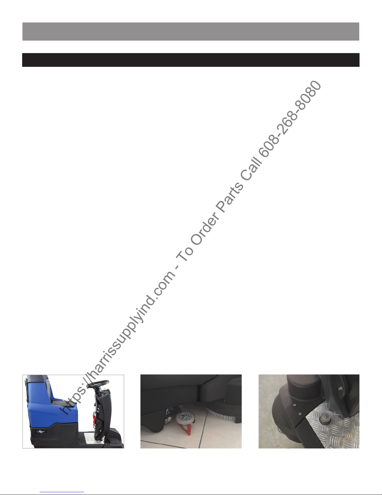
2. MACHINE DESCRIPTION
Large space for operator Squeegee Brake pedal
https://harrissupplyind.com-ToOrderPartsCall608-268-8080