Powrmatic HEM-NVx Series User guide
Stamm International Corporation
PO Box 1929
Fort Lee, NJ 07024
Tel: 201-947-1700
Fax: 201-947-9662
E-mail: stamminc@pobox.com
Stamm International HQ
www.powrmatic.co.uk
www.powrmatic.co.uk
®
Powrmatic Limited
Hort Bridge, Ilminster
Somerset
TA19 9PS
tel: +44 (0) 1460 53535
fax: +44 (0) 1460 52341
e-mail: [email protected]
web: www.powrmatic.co.uk
Powrmatic Ireland
45 Broomhill Close
Tallaght
Dublin 24
tel: +353 (0) 1452 1533
fax: +353 (0) 1452 1764
e-mail: [email protected]
web: www.powrmatic.ie
Getting In Touch
Powrmatic pursues a policy of continues improvement in both design and performance of its products and therefore reserves the right to change, amend or
vary specifications without notice. Whilst the details contained herein are believed to be correct they do not form the basis of any contract and interested
parties should contact the Company to confirm whether any material alterations have been made since publication of this brochure.
EURO-AIR
QUALITY
ICOM
Energy Association
More information is available from our website by scanning the following QR code.
HEM
User, Installation & Servicing Manual
Issue 3.6 Mar 2020
Doc Ref: M103 Issue 3.6 Mar 2020
ErP COMPLIANT
SEPTEMBER 2018
(NVx & SL)

page no. 2 of 44 HEMNVx & HEMSL Range Users, Installation & Servicing Instructions Doc Ref M103 issue 3.6 Mar 2020.
www.powrmatic.co.uk
Important: This certificate
must be kept with the appliance
Failure to provide a copy of the commissioning sheet invalidates the heater warranty
----------------------------------------------------
Powrmatic Ltd, Hort Bridge, Ilminster, Somerset, TA19 9PS
Tel: 01460 53535 Fax: 01460 52341
This is to certify that this heater is guaranteed for two years parts and one year labour from the date
of original commissioning. The heater must be commissioned within 4 weeks of installation.
To make a claim
In the first instance you must contact your appliance supplier, or installer and provide:-
1. The appliance type and serial number.
2. The original commissioning documentation. As much detail as possible on the fault.
3. Your supplier, or installer, will then contact Powrmatic to make a guarantee claim on your behalf.
Conditions of Guarantee
1. The heater must have been installed by a competent qualified installer, and in
accordance with the manufacturer’s instructions, building regulations and local regulations.
2. The heater has been professionally commissioned, within 4 weeks of installation, and a copy of
the commissioning sheet returned to Powrmatic.
3. The heater has been maintained on a yearly basis by a competent and qualified servicing
company.
4. The heater has been used in accordance with the manufacturer’s instructions.
5. The correct specification fuel has been used.
6. No unauthorised repairs of modifications have been made. Powrmatic ‘General Conditions of
Sales’ have been observed.
7. Except for the obligation of Powrmatic Ltd to perform warranty repairs during the guarantee
period, Powrmatic will not be liable in respect of any claim for direct or indirect consequential
losses, including loss of profits or increased cost arising from loss of use of the heater, or any
event arising there from.
Exclusions
Consumables such as gaskets, ignition electrodes, flame rectification electrodes, fusible links, control
batteries are all excluded from guarantee.
CertificateOfGuarantee
Certificate of Guarantee
®

page no. 3 of 44
HEMNVx & HEMSL Range Users, Installation & Servicing Instructions Doc Ref M103 issue 3.6 Mar 2020.
Title Section Contents Page
User Instructions 4
Pre Installation
1.1 Introduction 5
Duties 6
Dimensions 6
1.2 Technical data 10
1.3 General Requirements 12
Installation
2.1 Fitting the unit 15
2.2 General Identification of Items 19
2.3 Electrical Cable Installation 20
2.4 Wiring Terminal Connections 20
2.5 Wiring Diagrams 22
2.6 Commissioning and Testing 26
2.7 Servicing 30
Additional Documents
3.1 Fault Finding Flow Chart 33
3.2 List of Parts 34
Appendices
1. Information required for ecodesign (ErP) Directive 2009/125 HEM NVx 36
2. Information required for ecodesign (ErP) Directive 2009/125 HEM SL 37
3. Flueing and Ventilation requirements for 'stand alone' units 38
Users,InstallationandServicingInstructions
CONTENTS
Contents
page no. 4 of 44 HEMNVx & HEMSL Range Users, Installation & Servicing Instructions Doc Ref M103 issue 3.6 Mar 2020.
D) Description of Operation
Important: The heater must NOT be
controlled by switching ON and OFF the
main electrical supply to it.
1) Standard Units
The ignition sequence commences each time the
external controls e.g. Time clock, room thermostat etc.
call for heat. The internal exhaust fan will run and, when
sufficient combustion airflow is proved by the air pressure
switch, the ignition spark will be generated, the main gas
valve opens and the burners light. The heater fan must
start a maximum of 2 minutes after the burners light.
When the external controls are satisfied the burners
will be turned off and the main fan is required to run on
sufficiently to dissipate the heat from the unit. If the
burners fail to light the control box will make another four
attempts at ignition.
2) High / Low & Modulating Units
When the burners are alight, the heat output will be
controlled either to high fire or low fire or, in the case of
modulating units, to any point between high and low fire;
depending on the requirements of the space being heated
and the external controls fitted.
3) Overheat Thermostat
This operates if high temperatures within the heater are
detected, the burners are turned off and a Red indicator
switch light on the front panel is illuminated. The fault
condition must be identified and rectified.
When the unit has cooled, push the Red indicator switch
inside the front panel to reset the limit thermostat
interlock relay, the red indicator light will go out and the
unit is operational again.
Note: The limit thermostat(s) can only be reset
once the unit has cooled down.
Unless the cause of the fault condition is
readily obvious, for example a power cut whilst
the heater was operating, a service engineer should be
contacted.
E) Maintenance
To maintain efficient, reliable and safe operation of the
heater it must serviced annually by a qualified person.
If the heater has not been left operational
proceed as follows.
A) Checks before operating the Air
Heater
The following preliminary checks should be made before
lighting the heater(s)
a) Ensure that the ELECTRICAL supply to the heater is
switched OFF.
b) Check that any warm air delivery outlets are open.
c) Check that the thermostat is set.
d) Check that the clock control is set to an ON period.
e) Check that any other controls are calling for heat.
B) Operating the Air Heater
1. Switch on the electrical supply at the isolator
2. If the Red Limit indicator lamp is illuminated, identify
the limit stat, remove the black cap and press the reset
button.
3. The startup sequence will commence. After a short
delay the burners will light and the green ‘ON’ indicator on
the front of the heater will be illuminated.
4. If the burners fail to light the control box will
automatically restart the ignition sequence. If after 5
attempts at ignition the burners have still failed to light
the control box will go to lockout and the Amber lockout
lamp on the front of the heater (or on the low level remote
reset, or MC200/MC300 if fitted) will be illuminated. To
restart the ignition sequence depress the reset button on
the low level reset for about 1-2 seconds.
WARNING: If it is not possible to light the
heater after several attempts, contact the
installer or local service company.
C) To Shut Down the Air Heater
1) For Short Periods:
Turn the room thermostat to the OFF, or set to 'Summer
Mode'.
2) For Long Periods:
Complete step 1 above. Wait for 5 minutes and then turn
OFF the electrical supply at the isolator.
UserInstructions
page no. 5 of 44
HEMNVx & HEMSL Range Users, Installation & Servicing Instructions Doc Ref M103 issue 3.6 Mar 2020.
F) IMPORTANT
Free access must be maintained to and around the heater
for servicing purposes and the air supply to the heater
must not be restricted in any way. Combustible materials
must not be stored adjacent to the heater.
If at any time a gas leak is suspected, turn OFF the gas
supply at the meter and contact the local gas undertaking
immediately.
All Powrmatic heaters use gas and electricity to power
them, they may also contain moving parts such as pulleys
and belts. It would be hazardous to tamper with or
attempt to service unless you are a competent person in
the field of Gas and Electrical work.
If you have any safety questions reference the servicing
and installation of any of our heaters please do not
hesitate to contact our head office for expert advice. Your
safety is paramount to us.
Gas Safety (Installation & Use) (Amendment)
Regulations
It is law that all gas appliances are installed,
adjusted and, if necessary, converted by
qualified persons* in accordance with the
current issue of the above regulations.
Failure to install appliances correctly can lead to
prosecution. It is in your own interests and that of safety
to ensure that the law is complied with.
* Gas Safe Registered Engineer
The HEM Range are gas-fired insertion heaters covering
a range of heat outputs from 10.0kW to 200.0kW. They
are certified for use on Natural Gas, Group H - G20**.
Appliance Categories are Cat II2H (GB, IE). All units are
CE certified and conform to all the European directives
stated in section 1.3.1
HEM heaters are based on aluminised mild steel tube
heat exchanger elements with each tube having dedicated
inshot burners, a closed combustion circuit and have an
internal exhaust fan, mounted downstream of the heat
exchanger, to evacuate the products of combustion and
draw in air for combustion, a fully automatic control for
ignition, flame sensing, gas supply control and safety
functions.
Standard units are for internal use and are supplied
without a burner/controls housing for insertion into air
handling units or duct sections. Each unit is fitted with a
condense drain point from an all stainless steel exhaust
box. Optional items include a room sealed burner/controls
housing, T316 stainless steel heat exchanger tubes and
units specifically designed for fresh air input and where
condensate may be generated.
IMPORTANT
Service and Maintenance Engineers shall
ensure that replacement items are fitted,
adjusted and set in accordance with the
data and detail set out in these instructions. If in doubt
consult Powrmatic Technical Department.
Gas Safety (Installation & Use) Regulations 1998
It is law that all gas appliances are installed,
adjusted and, if necessary, converted by
qualified persons* in accordance with the
current issue of the above regulations.
Failure to install appliances correctly can lead to
prosecution. It is in your own interests and that of safety
to ensure that the law is complied with.
* Gas Safe Registered Engineer
* LPG conversion kits available.
1.1Introduction
UserInstructions
page no. 6 of 44 HEMNVx & HEMSL Range Users, Installation & Servicing Instructions Doc Ref M103 issue 3.6 Mar 2020.
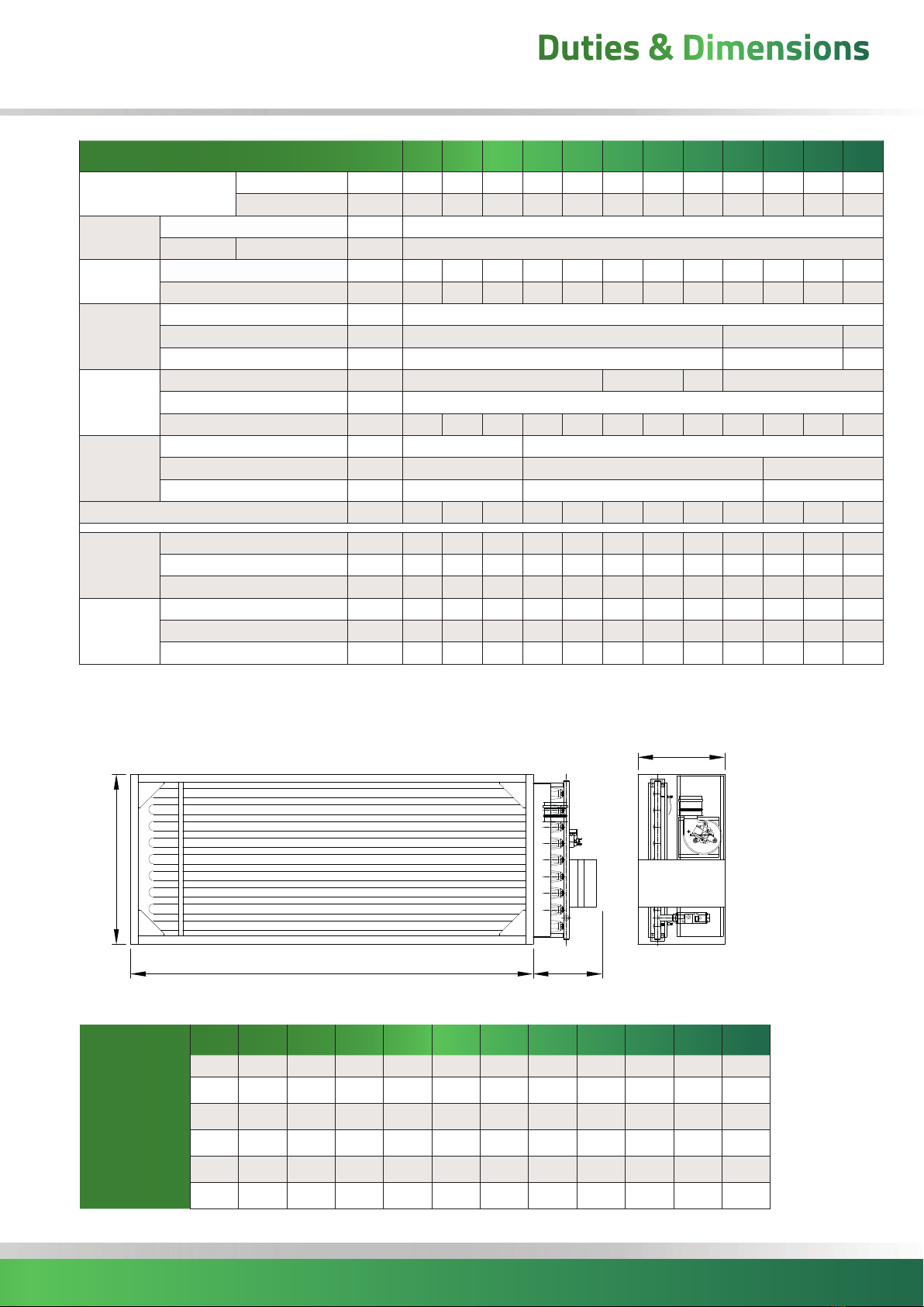
C
B
A D
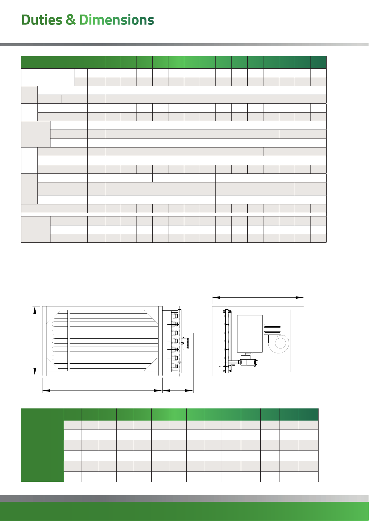
Model 10-3 15-4 18-5 25-5 30-6 40-8 50-6 60-7 75-9 100-12 110-13 125-15 150-18 175-21
Dimension
A550 550 550 680 680 680 1050 1050 1050 1050 1050 1050 1050 1050
B305 458 458 531 531 741 531 601 741 950 1132 1272 1482 1690
C590 590 590 648 648 648 800 800 800 800 930 930 930 930
D400 400 380 400 380 380 400 400 400 400 500 500 500 500
Flue Diameter 80 80 80 100 100 100 100 130 130 130 130 130 130 130
Model HEM-NVx 10-3 15-4 18-5 25-5 30-6 40-8 50-6 60-7 75-9 100-12 110-13 125-15 150-18 175-21
Output Max kW 9.6 14.5 17.7 23.6 27.4 36.0 44.8 54.2 67.6 91.9 98.0 112.0 134.9 154.4
Min. kW 5.0 9.8 11.9 15.7 18.2 23.2 29.0 36.4 49.6 62.5 66.0 76.5 78.8 112.8
Temp Rise Δt °C 35
Air Off Max °C 70
Airflow Min. Airflow m3/s 0.34 0.44 0.58 0.71 0.86 1.01 1.55 1.94 2.28 2.78 2.99 3.39 4.14 4.67
Min. Airflow ΔP Pa 43 26 45 32 47 31 59 67 59 54 43 43 47 45
Electrics
V/ph/Hz 1N/230V/50~
Current A/pha 0.30 0.9
Power kW 0.07 0.21
Fuel
Natural
Gas
Connection BSP/Rc ¾1¼
Minimum Inlet Pressure mbar 20.0
Rate m3/h 1.09 1.72 2.09 2.77 3.22 4.18 5.26 6.52 8.10 10.92 11.62 13.37 16.27 18.40
Flue
Diameter mm ø 80 100 130
Max Length Type B m 14 16 3m max @
Ø130mm**
Max Length Type C m 14* 16* n/a
Nett Weight (single units) kg 38 45 53 60 68 74 91 114 123 140 145 168 195 230
Two
Modules in
Series
Max Δt = 70°C
Heat Output kW 19.2 29.1 35.4 47.2 54.9 72.0 89.5 108.4 135.2 183.8 196.0 224.0 269.7 308.8
Min. Airflow m3/s 0.34 0.44 0.58 0.71 0.86 1.01 1.55 1.94 2.28 2.78 2.99 3.39 4.14 4.67
Min. ΔP Pa 87 52 91 65 95 62 117 134 119 108 86 86 93 91
* length shown is maximum calculated length see section 2.1.4.2 ** see section 2.1.4.1 for longer flue runs
Duties & Dimensions
HEM-NVx
page no. 7 of 44
HEMNVx & HEMSL Range Users, Installation & Servicing Instructions Doc Ref M103 issue 3.6 Mar 2020.
C
B
A D
Model 30-6 45-9 50-6 60-12 75-9 75-15 90-18 100-12 125-15 150-18 175-21 200-24
Dimension
A1250 1250 1850 1250 1850 1250 1250 1850 1850 1850 1850 1850
B531 741 531 950 741 1272 1482 950 1272 1482 1690 1900
C400 400 400 400 400 400 400 400 400 400 400 530
D450 450 450 450 450 450 450 450 500 500 500 550
Flue Diameter 100 100 100 130 130 130 130 130 130 130 130 130
Model - HEM-SL 30-6 45-9 50-6 60-12 75-9 75-15 90-18 100-12 125-15 150-18 175-21 200-24
Output Max kW 27.0 40.5 45.0 54.2 68.5 67.5 80.4 88.7 116.7 135.7 160.8 178.3
Min kW 15.0 23.5 23.9 36.4 44.6 41.5 41.6 62.4 70.5 79.9 82.6 108.3
Temp Rise Δt °C 35
Air Off Max °C 70
Airflow Min. Airflow m3/s 0.97 1.45 1.61 1.94 2.42 2.42 2.90 3.23 4.03 4.84 5.64 6.45
Min. Airflow ΔP Pa 16 17 20 18 21 15 19 22 19 19 20 21
Electrics
V/ph/Hz 1N/230V/50~
Current A 0.30 0.90 3.50
Power kW 0.07 0.21 0.80
Fuel
Natural Gas
Connection BSP/Rc ¾ 1¼ ¾ 1¼
Minimum Inlet Pressure mbar 20
Rate m3/s 3.35 4.76 5.29 6.52 8.15 8.26 9.59 10.31 13.76 16.22 19.43 21.81
Flue
Diameter mm ø 100 130
Max. Length Type B m 14 16 3m max @ Ø130mm**
Max. Length Type C m 14* 16* n/a
Nett Weight (single units) kg 59 85 79 118 106 139 165 130 185 204 235 265
Two Modules
in Series
Max Δt @ 50°C
Heat Output kW 54.0 81.0 90.0 108.4 137.0 135.0 160.8 177.3 233.4 271.4 321.5 356.6
Min. Airflow m3/s 0.97 1.45 1.61 1.94 2.42 2.42 2.90 3.23 4.03 4.84 5.64 6.45
Min. ΔP Pa 27 29 33 30 35 25 31 37 31 32 34 35
Three Modules
in Series
Max Δt @ 75°C
Heat Output kW 81.0 121.5 135.0 162.6 205.5 202.5 241.2 266.0 350.1 407.1 482.3 535.0
Min. Airflow m3/s 1.04 1.56 1.73 2.08 2.59 2.59 3.11 3.46 4.32 5.18 6.05 6.91
Min. ΔP Pa 46 49 56 51 59 43 52 63 52 54 57 58
length shown is maximum calculated length see section 2.1.4.2 * see section 2.1.4.1 for longer flue runs
Duties & Dimensions
HEM-SL

page no. 8 of 44 HEMNVx & HEMSL Range Users, Installation & Servicing Instructions Doc Ref M103 issue 3.6 Mar 2020.
Note:
HEM NVx
The above data refers to a single module pressure drop. For twin models, refer to manufacturer.
10-3
720
1800
2880
3960
5040
6120
7200
7200
8280
9360
10440
11520
12600
13680
14760
14760
15840
16920
18000
19080
20160
21240
22320
22320
23400
24480
25560
26640
27720
28800
29880
29880
30960
32040
33120
34200
35280
36360
37440
37440
38520
39600
40680
41760
42840
43920
45000
45000
46080
47160
48240
49320
50400
51480
52560
52560
53640
54720
55800
56880
57960
59040
60120
60120
Airflow m³/h
15-4
18-5
25-5
30-6
40-8
50-6
60-7
75.9
100-12
110-13 125-15
150-18
175-21
200-24
Pressure Drop Graph
HEM-NVx
Airow m³/h
10-3
15-4
18-5
25-5
30-6
40-8
50-6
60-7
75.9
100-12
110-13 125-15
150-18
175-21

page no. 9 of 44
HEMNVx & HEMSL Range Users, Installation & Servicing Instructions Doc Ref M103 issue 3.6 Mar 2020.
30-6
45-9
50-6
60-12
75-9
75-15
90-18
100-12
125-15
2160
3600
5040
6480
7920
9360
10800
10800
12240
13680
15120
16560
18000
19440
20880
20880
22320
23760
25200
26640
28080
29520
30960
30960
32400
33840
35280
36720
38160
39600
41040
41040
42480
43920
45360
46800
48240
49680
51120
51120
52560
54000
55440
56880
58320
59760
Airflow m³/h
150-18
175-21
200-24
Note:
HEM-SL
The above data refers to a single module pressure drop. For twin & triple models, refer to manufacturer.
Pressure Drop Graph
HEM-SL
Airow m³/h
page no. 10 of 44 HEMNVx & HEMSL Range Users, Installation & Servicing Instructions Doc Ref M103 issue 3.6 Mar 2020.
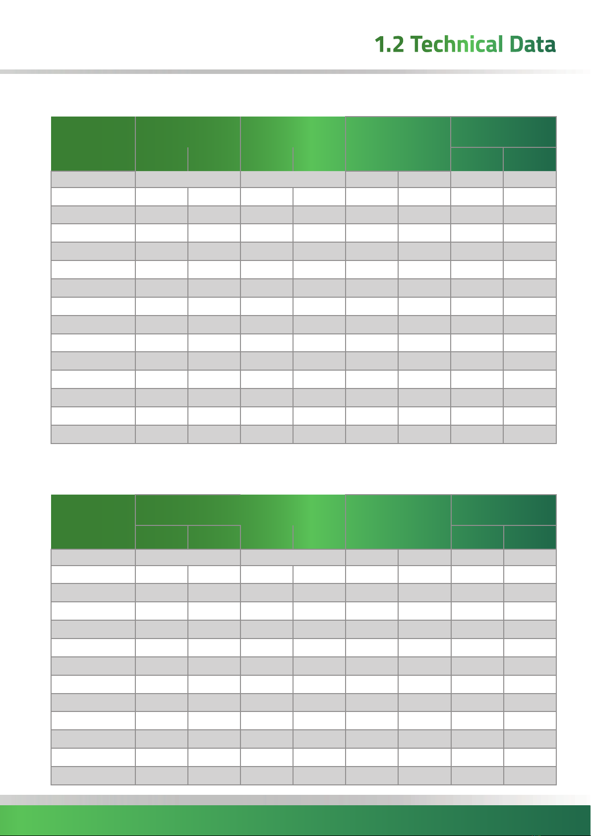
HEM-NVx Injectors
(Max) (Min)
Burner
Pressure Gas Rate
(nominal) Burner
Pressure Gas Rate
(nominal)
MODEL No. Size mm Marked mbar m³/h mbar m³/h
HEMNVx 10-3 31.67 380 8.6 1.1 2.7 0.6
HEMNVx 15-4 41.67 380 12.0 1.7 5.0 1.2
HEMNVx 18-5 51.67 380 12.0 2.1 5.0 1.4
HEMNVx 25-5 51.94 500 12.1 2.8 5.0 1.9
HEMNVx 30-6 61.94 500 12.0 3.2 5.0 2.2
HEMNVx 40-8 81.94 500 10.3 4.2 5.0 2.8
HEMNVx 50-6 62.54 750 10.2 5.3 4.7 3.5
HEMNVx 60-7 72.54 750 11.3 6.5 5.0 4.3
HEMNVx 75-9 92.54 750 10.8 8 .1 6.3 6 .1
HEMNVx 100-12 12 2.54 750 11.4 10.9 5.0 7.6
HEMNVx 110-13 7+6 2.54 750 10.4 11.6 5.0 7.9
HEMNVx 125-15 9+6 2.54 750 10.8 13.4 5.0 9.2
HEMNVx 150-18 9+9 2.54 750 10.5 16.3 4.6 10.6
HEMNVx 175-21 12+9 2.54 750 11.0 18.4 5.0 13.3
Injector Sizes & Burner Pressures - Natural Gas - Group H - G20 Net CV (Hi = 34.02MJ/m³)
HEM-SL Injectors
(Max) (Min)
Burner
Pressure Gas Rate
(nominal) Burner
Pressure Gas Rate
(nominal)
MODEL No. Size mm Marked mbar m³/h mbar m³/h
HEMSL 30-6 61.94 500 12.0 3.4 4.0 1.9
HEMSL 45-9 91.94 500 10.9 4.8 2.9 2.8
HEMSL 50-6 62.54 750 10.0 5.3 1.6 2.9
HEMSL 60-12 12 1.94 500 11.3 6.5 5.0 4.3
HEMSL 75-9 92.54 750 10.6 8.2 4.6 5.3
HEMSL 75-15 15 1.94 500 12.1 8.3 4.0 4.6
HEMSL 90-18 18 1.94 500 10.5 9.6 3.1 4.9
HEMSL 100-12 12 2.54 750 10.0 10.3 5.0 7.4
HEMSL 125-15 15 2.54 750 10.0 13.8 5.0 9.6
HEMSL 150-18 18 2.54 750 9.70 16.2 5.0 10.6
HEMSL 175-21 21 2.54 750 9.70 19.4 5.0 12.1
HEMSL 200-24 24 2.54 750 10.3 21.8 5.5 14.1
1.2 Technical Data
Minimum Inlet Pressure = 20mbar
page no. 11 of 44
HEMNVx & HEMSL Range Users, Installation & Servicing Instructions Doc Ref M103 issue 3.6 Mar 2020.
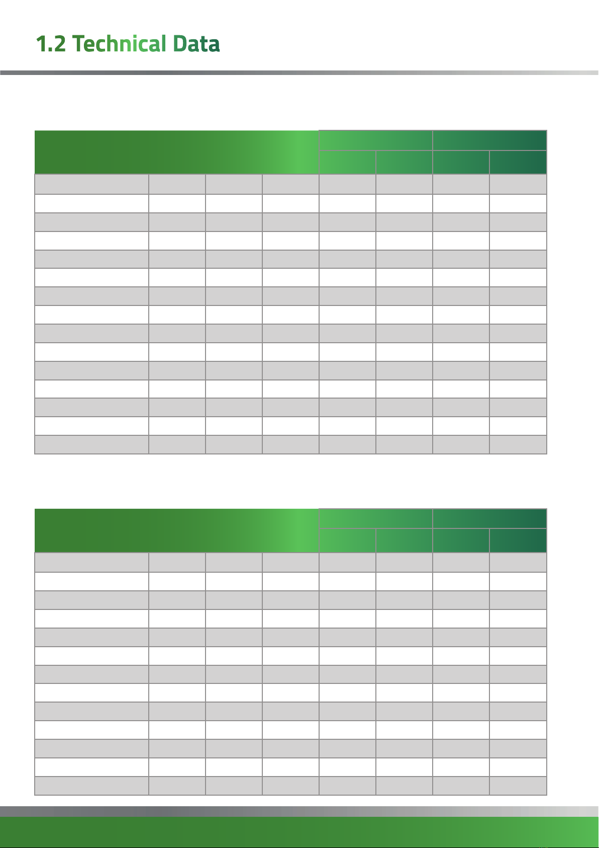
Heater Specifications cont - Natural Gas
HEM-NVx High Fire Low Fire
Min Air Flow
Weights
Input
(Nett) Output Input
(Nett) Output Module
only Packaging
MODEL kW kW m³/s m³/h kg kg
HEMNVx 10-3 10.3 9.6 5.6 5.0 0.34 1220 38 12
HEMNVx 15-4 16.3 14.5 11.0 9.8 0.4 1600 45 12
HEMNVx 18-5 19.8 17.7 13.4 11.9 0.6 2070 53 15
HEMNVx 25-5 26.2 23.6 17.8 15.7 0.7 2550 60 15
HEMNVx 30-6 30.5 27.4 20.6 18.2 0.9 3100 68 15
HEMNVx 40-8 39.6 36.0 26.4 23.2 1.0 3650 74 15
HEMNVx 50-6 49.7 44.8 33.0 29.0 1.5 5570 91 18
HEMNVx 60-7 61.6 54.2 41.0 36.4 1.9 6984 114 18
HEMNVx 75-9 76.6 67.6 57.7 49.6 2.3 8208 123 18
HEMNVx 100-12 103.3 91.9 71.9 62.5 2.8 1000 140 21
HEMNVx 110-13 109.9 98.0 75.0 66.0 3.0 10750 145 21
HEMNVx 125-15 126.4 112.0 86.5 76.5 3.4 12200 168 25
HEMNVx 150-18 153.9 134.9 100.2 78.8 4.1 14900 195 30
HEMNVx 175-21 174.0 154.4 125.7 112.8 4.7 16800 230 32
HEM-SL High Fire Low Fire
Min Air Flow
Weights
Input
(Nett) Output Input
(Nett) Output Module
only Packaging
MODEL kW kW m³/s m³/h kg kg
HEMSL 30-6 31.7 27.0 17.9 15.0 1.0 3492 59 15
HEMSL 45-9 45.0 40.5 26.3 23.5 1.5 5220 85 15
HEMSL 50-6 50.0 45.0 27.3 23.9 1.6 5796 79 18
HEMSL 60-12 61.6 54.2 41.0 36.4 1.9 6984 118 15
HEMSL 75-9 77.0 68.5 50.2 44.6 2.4 8712 105 18
HEMSL 75-15 78.0 67.5 43.6 41.5 2.4 8712 139 18
HEMSL 90-18 90.6 80.4 46.2 41.6 2.9 10440 165 18
HEMSL 100-12 97.5 88.7 69.5 62.5 3.2 11628 130 21
HEMSL 125-15 130.0 116.7 85.4 70.5 4.0 14508 185 25
HEMSL 150-18 153.2 135.7 99.8 79.9 4.8 17424 204 30
HEMSL 175-21 183.6 160.8 114.0 82.6 5.6 20304 235 32
HEMSL 200-24 20 6.1 178.3 133.2 108.3 6.5 23220 265 35
1.2 Technical Data
page no. 12 of 44 HEMNVx & HEMSL Range Users, Installation & Servicing Instructions Doc Ref M103 issue 3.6 Mar 2020.
1.3.1. Related Documents
All HEM heaters comply with the following European
Directives:
Energy Related Product Directive: 2009/125/EC*
Gas Appliance Directive: 2009/142/EC
Electromagnetic Compatibility Directive: 2004/108/EC
Low Voltage Directive: 2006/95/EC
Machinery Directive: 2006/42/EC
Air heater(s) must be installed in accordance with BS6230
and BS5440 plus any relevant requirements of local and
national building codes. * where appropriate.
1.3.2 Electrical Supply
Wiring external to the air heater must be installed in
accordance with the I.E.E. Regulations for Electrical
Installations and any local regulations which apply.
All standard heaters are supplied by 230V - 1ph, 50Hz.
The method of connection to the main electricity supply
must:-
- facilitate the complete electrical isolation of the unit(s)
via a suitable fused isolator (see section 2.4.5 for ratings)
- be in a readily accessible position adjacent to the unit(s)
- serve only the unit(s)
- have a contact separation of at least 3mm in all poles.
See the accompanying wiring diagram for the heater
electrical connections.
1.3.3 Gas Supply
A servicing valve and union to facilitate servicing must
be fitted to the gas inlet pipe work of the heater. The
gas supply must be completed in solid pipe work and be
adequately supported.
WARNING: When completing the final gas
connection to the heater do not place undue
strain on the gas pipe work of the heater.
1.3.3.1 Service Pipes
The local gas undertaking should be consulted at the
installation planning stage in order to establish the
availability of an adequate supply of gas to suit the
building requirements. An existing service pipe must not
be used without prior consultation with the local gas
undertaking.
1.3.3.2 Meters
An existing meter should be checked, preferably by the
gas undertaking, to ensure that the meter is adequate
to deal with the total rate of gas supply required by all
connected equipment.
1.3.3.3. Installation Pipes
Installation pipes should be fitted in accordance with IGE/
UP/2. Pipe work from the meter to the air heater must be
of adequate size.
Do not use pipes of a smaller size than the inlet gas
connection of the heater.
The complete installation must be tested for soundness
as described in the above Code.
1.3.4VentilationRequirementsfor
AHU's
Refer to tables detailed on next page for calculated free
areas of ventilation grilles.
Refer to Index 1 for Air inlet/exhaust flue and ventilation
sketches
1.3.4.1 Type B flued installations.
Where AHU's are installed within the heated space
(ie not in a plant room) and having a building design air
change rate of greater than 0.5/h, additional provision for
ventilation is not required.
If the building design air change rate is less than 0.5/h,
additional provision for natural or mechanical ventilation
is required.
These being:
Natural Ventilation: Grilles having a free area of at least
2cm² per kW of rated heat input shall be provided at low
level i.e. below the level of the heater flue connection.
or
Mechanical Ventilation: Must ensure that the space air
change rate is at least 0.5/h, must be of the ‘input’ type
and interlocked to ensure the heaters cannot work if the
input system is not working.
1.3GeneralRequirements
page no. 13 of 44
HEMNVx & HEMSL Range Users, Installation & Servicing Instructions Doc Ref M103 issue 3.6 Mar 2020.
1.3.4.1 Type B flued installations.
Where AHU's are installed in a plant room (ie not
within the heated space) having combustion air drawn
directly from the room and connected to a flue that
evacuates the products of combustion directly from
the room additional provision for natural or mechanical
ventilation is required.
These being:
Natural Ventilation:
There must be permanent air vents communicating
directly with the outside air, at high level and at low level.
For Plant Rooms
Low level (inlet) 4cm²/kw of total rated net heat input
High level (outlet) 2cm²/kw of total rated net heat input
Mechanical Ventilation: The minimum flow rate of
ventilation shall be 4.14m³/h per kilowatt of total rated
heat input.
1.3.4.3 Type C flued installations.
Note Not applicable for models 175 and 200
Where AHU's are Installed within the heated space
(ie not in a plant room) having combustion air ducted
to the appliance and combustion products ducted to the
outside air, NO additional provision for the supply of
either combustion air or for combustion products dilution
or additional provision for the supply of air is necessary.
1.3.4.3 Type C flued installations.
Where AHU's are installed in a plant room (ie
not within the heated space) having g combustion
air ducted to the appliance and combustion products
ducted to the outside, air vents shall be provided and be
permanently open.
To room or internal space
Low level (inlet) 10cm²/kw of total rated net heat input
High level (outlet) 10cm²/kw of total rated net heat input
Direct to outside air
Low level (inlet) 5cm²/kw of total rated net heat input
High level (outlet) 5cm²/kw of total rated net heat input..
1.3.5 Burner/Controls Enclosure.
Where the flue system is a Type C12 or C32 the burner
and controls enclosure, whether it is part of the unit the
module is fitted in or an enclosure in its own right, must
meet the requirement of BS EN1020 Clause 6.1.1.24 i.e.
the air leakage rate from the enclosure shall not exceed
0.5m³/h per kW of heat input, with a maximum of 25 m³/h.
With the flue connected the terminal is sealed, any access
door is closed and the gas inlet is isolated. Air is passed
into the appliance via a flow meter and the air flow rate is
noted when the pressure inside the enclosure is steady at
0,5mbar above the atmospheric pressure.
NOTE A convenient method of testing the
appliance is to enclose the terminal in a plastic
bag into which an air entry pipe and tube
connected to a pressure gauge can be fitted.
1.3GeneralRequirements

page no. 14 of 44 HEMNVx & HEMSL Range Users, Installation & Servicing Instructions Doc Ref M103 issue 3.6 Mar 2020.
Type B22 Installation (these refer to section
2.2 of these instructions)
Air vents shall be permanently open.
In all cases gures are per heater installed.
For multi heater installations the appropriate values for
each heater must be added together
Type C12 or C32 Installation (these refer to section 2.2 of
these instructions)
Air vents shall be permanently open.
Figures are for heaters in plant rooms or enclosures ONLY
In all cases gures are per heater installed.
For multi heater installations the appropriate values for each heater must be
added together.
Heat
Input
kW
In the heated
space
In a plant room, ventilation
to outside
Ventilation is to a room or
internal space
Ventilation is to a outside
air
Low level grille.
Free area cm² Low level grille.
Free area cm² High level grille.
Free area cm² Low level grille.
Free area cm² High level grille.
Free area cm² Low level grille.
Free area cm² High level grille.
Free area cm²
HEMNVx 10-3 10.3 20.6 41.2 20.6 103.0 103.0 51.5 51.5
HEMNVx 15-4 16.3 32.6 65.2 32.6 163.0 163.0 81.5 81.5
HEMNVx 18-5 19.8 39.6 79.2 39.6 198.0 198.0 99.0 99.0
HEMNVx 25-5 26.2 52.4 104.8 52.4 262.0 262.0 131.0 131.0
HEMNVx 30-6 30.5 61.0 122.0 61.0 305.0 305.0 152.5 152.5
HEMNVx 40-8 39.6 79.2 158.4 79.2 396.0 396.0 198.0 198.0
HEMNVx 50-6 49.7 99.4 198.8 99.4 497. 0 497. 0 248.5 248.5
HEMNVx 60-7 61.6 123. 2 246.4 123.2 616.0 616.0 308.0 308.0
HEMNVx 75-9 76.6 153.2 306.4 153.2 766.0 766.0 383.0 383.0
HEMNVx 100-12 103.3 206.6 413.2 206.6 1033.0 1033.0 156.5 156.5
H EMN Vx 110 -13 109.9 219.8 439.6 219.8 1099.0 1099.0 549.5 549.5
HEMNVx 125-15 126.4 252.8 505.6 252.8 2528.0 2528.0 1264.0 1264.0
HEMNVx 150-18 153.9 307.8 615.6 307. 8 n/a
HEMNVx 175-21 174.0 348.0 696.0 348.0
Type B22 Installation (these refer to section
2.2 of these instructions)
Air vents shall be permanently open.
In all cases gures are per heater installed.
For multi heater installations the appropriate values for
each heater must be added together
Type C12 or C32 Installation (these refer to section 2.2 of
these instructions)
Air vents shall be permanently open.
Figures are for heaters in plant rooms or enclosures ONLY
In all cases gures are per heater installed.
For multi heater installations the appropriate values for each heater must be
added together.
Heat
Input
kW
In the heated
space
In a plant room, ventilation
to outside
Ventilation is to a room or
internal space
Ventilation is to a outside
air
Low level grille.
Free area cm² Low level grille.
Free area cm² High level grille.
Free area cm² Low level grille.
Free area cm² High level grille.
Free area cm² Low level grille.
Free area cm² High level grille.
Free area cm²
HEMSL 30-6 31.7 63.4 126.8 63.4 317.0 317.0 158.5 158.5
HEMSL 45-9 45.0 90.0 180.0 90.0 450.0 450.0 225.0 225.0
HEMSL 50-6 50.0 100.0 200.0 100.0 500.0 500.0 250.0 250.0
HEMSL 60-12 61.6 123.2 246.4 123.2 616.0 616.0 308.0 308.0
HEMSL 75-9 77.0 154.0 308.0 154.0 770.0 770.0 385.0 385.0
HEMSL 75-15 78.0 156.0 312.0 156.0 780.0 780.0 390.0 390.0
HEMSL 90-18 90.6 181.2 362.4 181.2 906.0 906.0 453.0 453.0
HEMSL 100-12 97. 5 195.0 390.0 195.0 975.0 975.0 4 8 7. 5 4 87. 5
HEMSL 125-15 130.0 260.0 520.0 260.0 1300.0 1300.0 650.0 650.0
HEMSL 150-18 153.2 306.4 612.8 306.4
n/aHEMSL 175-21 183.6 3 67. 2 734.4 3 67. 2
HEMSL 200-24 206.1 412.2 824.4 412.2
1.3.6.VentilationRequirements
HEM-NVx
HEM-SL
1.3GeneralRequirements
page no. 15 of 44
HEMNVx & HEMSL Range Users, Installation & Servicing Instructions Doc Ref M103 issue 3.6 Mar 2020.
Before installation, check that the:
- local distribution conditions, nature of gas and pressure,
and the current state adjustment of the appliance are
compatible,
- local electrical supply conditions are compatible with the
electrical data given on the data plate.
2.1.1.Unpacking
The module has been fired and tested at the factory prior
to despatch. Check the despatch documents and the data
plate affixed to the module to confirm that it is as ordered
and compatible with the gas and electrical supplies on
site.
Read the entire document before commencing
installation.
2.1.2 Module Types
Modules are available for:
a) Use within an additional casing e.g. an air handling unit.
i.e no factory fitted burner /controls housing.
b) Internal use with a burner /controls housing.
c) For external use with a weatherproof burner/controls
housing.
Type a) and type b) can be for either B22 (combustion air
taken from the internal space) or C12/C32 (combustion air
taken from outside) flue configurations.
2.1.3 Module Fitment
Modules must be handled safely and lifted using the fitted
lifting brackets. These can be removed on installation if
necessary. The module should slide into the air handling
unit/duct section between top and bottom guide rails
sized to suit the module in question. It must be possible
to easily remove the module at a later date should this be
necessary.
There must be effective sealing between the module
burner/controls section so that there is no air leakage
from the main air flow path into the burner/controls
section.
Modules may be orientated so that the burner manifold(s)
is vertical or horizontal.
For external units please note:
The lowest edge of air inlets must be at least
500 mm above ground level. Access panels
and doors to be removed during normal
servicing shall be designed so that repeated removal and
replacement does not damage the insulation or impair the
waterproofing of the unit.
No opening (e.g. electrical wiring points) from the inside of
the appliance to the outside air shall permit the entry of a
16 mm diameter ball.
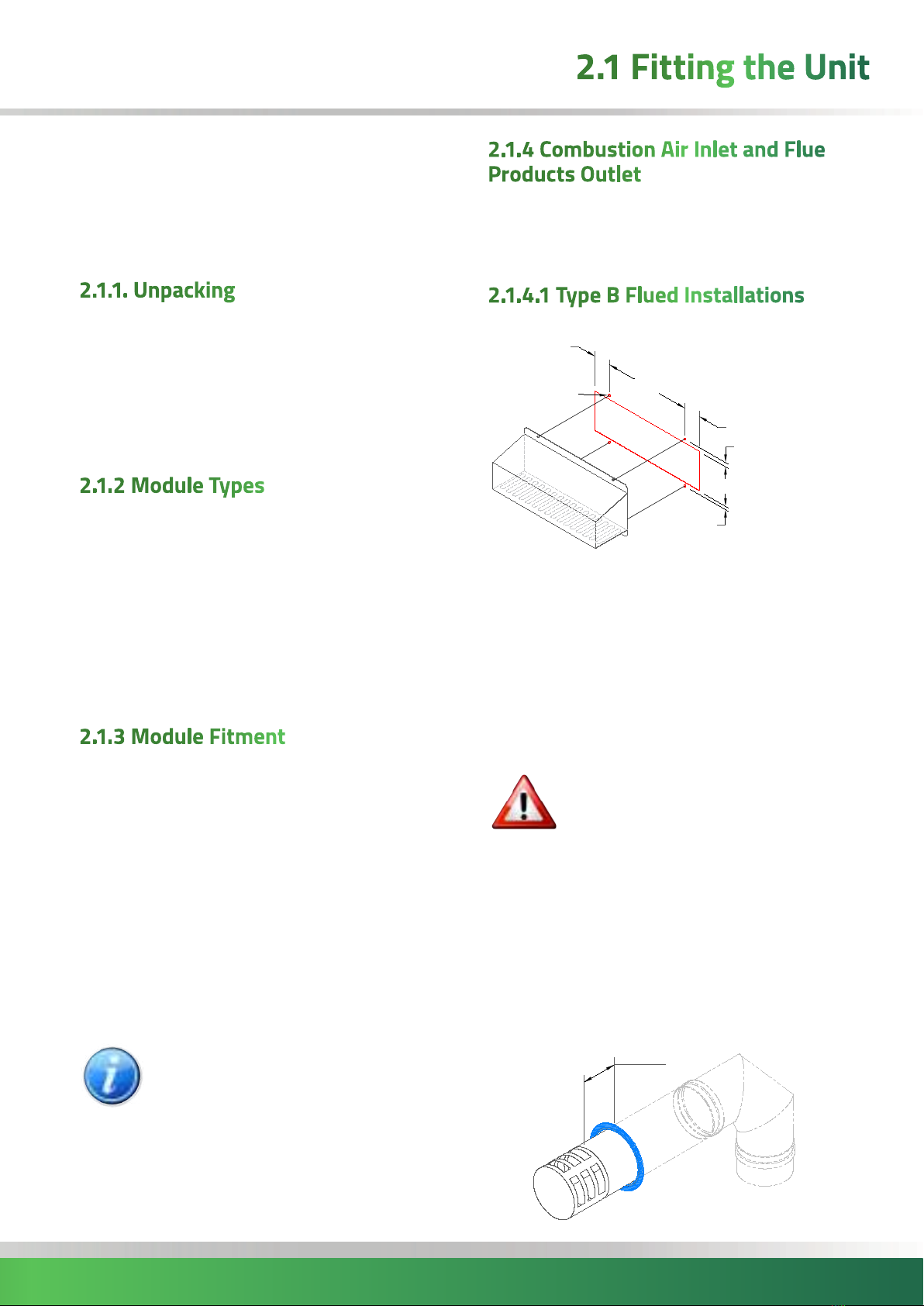
2.1.4 Combustion Air Inlet and Flue
Products Outlet
Combustion air inlet(s) and flue outlets must be
connected to each HEM unit so when the unit is installed,
their termination is at least 500mm from ground level.
2.1.4.1 Type B Flued Installations
The combustion
air inlet
attachment
requires an
aperture to be
cut and four
pilot holes to
be drilled in the
front plate of
the controls
compartment
to the following
dimensions and must be installed on a level plane.
The combustion air inlet attachment can then be offered
up to the front plate and secured using self tapping
screws ensuring a positive seal to prevent any ingress of
water.
Alternatively an air inlet orifice having a free area of at
least 110 cm² (app 105 x 105mm) can be cut into the
burner enclosure panel to facilitate the combustion air.
Two air inlet attachments (or free area of
220cm²) are required on models SL75-15;
SL90-18; NVx & SL125; NVx & SL150; NVx &
SL175.
Three air inlet attachments (or free area of
330cm²) are required on models HEM SL200
A flue outlet terminal is required with every module and
is connected to the exhaust fan. Flue outlet terminals can
be either standard 450mm long terminals or Powrmatic
approved flue system. Flue terminals may be extended by
the use of a Powrmatic approved flue piece with sealing
ring or cut down to suit the particular application ensuring
the flue terminal projects from the front plate by at least
75mm
min 75mm
2.1 Fitting the Unit
220
96
12
12
40.5
40.5
4 HOLES Ø3
page no. 16 of 44 HEMNVx & HEMSL Range Users, Installation & Servicing Instructions Doc Ref M103 issue 3.6 Mar 2020.
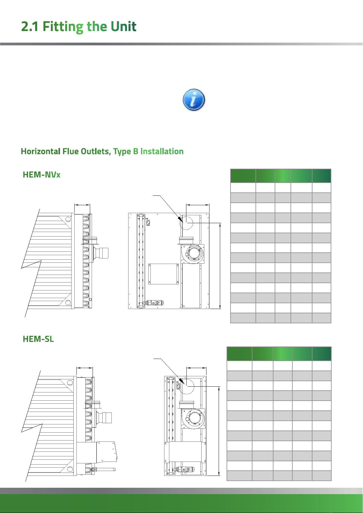
For horizontal type B flued installations a Combustion
Air Inlet and Flue Termination piece is supplied for each
module (two Combustion Air Inlets are supplied with
models HEMNVx 150 & 175). For Vertical type B flued
installations a Combustion Air Inlet and Flue Termination
piece is supplied for each module (two Combustion Air
Inlets are supplied with models HEMNVx 150 & 175).
The total calculated maximum permitted length of flue
system for sizes up to and including model 50 is 14m,
from model 60 to 125 is 16m. If an offset is required a set
Size A B C ØD
10-3 399 167 108 91
15-4 399 167 108 91
18-5 399 167 108 91
25-5 443 187 121.5 112
30-6 443 187 121.5 112
40-8 637 187 121.5 112
50-6 443 217 121.5 112
60-7 501 227 145.5 142
75-9 641 227 145.5 142
100-12 848 226 151.5 142
110-13 997 204 181 142
125-15 1137 204 181 142
150-18 1347 204 181 142
175-21 1554 204 181 142
A
B
HORIZONTAL FLUE POSITION
ØD HOLE FOR FLUE SEAL
C
A
B
HORIZONTAL FLUE POSITION
ØD HOLE FOR FLUE SEAL
C
HORIZONTAL FLUE POSITION
ØD HOLE FOR FLUE SEAL
A
BC
HORIZONTAL FLUE POSITION
ØD HOLE FOR FLUE SEAL
A
BC
Size A B C ØD
30-6 453.5 179 121.5 112
45-9 659 179 121.5 112
50-6 453.5 179 121.5 112
60-12 815 188 145.5 142
75-9 651 188 145.5 142
75-15 1172 188 145.5 142
90-18 1333 187 151.5 142
100-12 848 187 151.5 142
125-15 1135 35 180.5 142
150-18 1345 35 180.5 142
175-21 1552 35 180.5 142
200-24 1769 116 181 142
of 45° bends should be used being equivalent to 0.5m of flue
length. 90° bends may be used but each set will be equivalent
to 1.0m of flue length.
For HEM150/175/200 units: use Ø130 flue
system for a total calculated length of up to 3M,
Ø150 for a total calculated length in excess of
3M up to 9M, Ø180 for a total calculated length
in excess of 10m up to 18M and Ø200 for in
excess of 18m up to 24M.
HEM-NVx
HEM-SL
2.1 Fitting the Unit
HorizontalFlueOutlets,TypeBInstallation
Exhaust flue outlet positions are shown in the following diagrams and tables.
page no. 17 of 44
HEMNVx & HEMSL Range Users, Installation & Servicing Instructions Doc Ref M103 issue 3.6 Mar 2020.
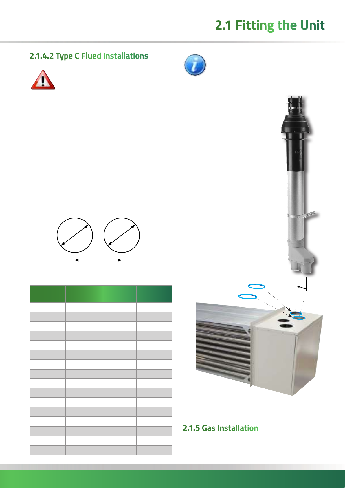
2.1.4.2 Type C Flued Installations
IMPORTANT:
Not applicable for models 150, 175 & 200
For Type C flued installations, a concentric flue system
should be used of the appropriate orientation.
The total calculated maximum permitted length of flue
system for sizes up to and including model 50 is 14m,
from model 60 to 125 is 16m. Concentric flue terminals are
equivalent to 5m of flue length. If an offset is required two
sets of 45° bends should be used each set being equivalent to
0.5m of flue length. 90° bends may be used but each set will
be equivalent to 1.0m of flue length.
Exhaust flue outlet positions are shown in the previous
diagrams and tables.
Air inlet holes should be cut to the dimensions in the
following table to accept the silicone seals supplied.
(where ØD is the actual cut size in the casing/sheet metal).
Type C Flue and air inlet cut hole sizes and centres
distances. (refer to table below)
HEMNVx HEMSL A CRS ØD
10-3 n/a 120 91
15-4 n/a 120 91
18-5 n/a 120 91
25-5 n/a 142 112
30-6 30-6 142 112
40-8 n/a 142 112
n/a 45-9 142 112
50-6 50-6 142 112
60-7 n/a 220 142
n/a 60-12 220 142
75-9 75-9 220 142
n/a 75-15 220 142
n/a 90-18 220 142
100-12 100-12 220 142
110-13 n/a 220 142
125-15 125-15 220 142
2.1 Fitting the Unit
The silicone seals supplied are not water tight
and should not be used in external vertical
applications. A suitable water tight seal or
sealant must be used in these instances
Silicone
Seals
A CRS
2.1.5GasInstallation
The whole of the gas installation, including the meter,
should be inspected and tested for soundness and purged
in accordance with the recommendations of IM/16:1988.
Simulated enclosure
A CRS
ØD
ØD
page no. 18 of 44 HEMNVx & HEMSL Range Users, Installation & Servicing Instructions Doc Ref M103 issue 3.6 Mar 2020.
2.1.8FlueSystem
Only flue systems supplied through Powrmatic Ltd may be
used with HEM modules. The flue outlet socket must be
connected via the provided flue system to outside air.
The maximum permitted length of flue system is shown in
duties on page 6 and 7. If an offset is required, two sets of
45° bends should be used each set being equivalent to 0.5m
of flue length. 90° bends may be used but each set will be
equivalent to 1.0m of flue length.
All outer joints must be finished with the provided locking
bands. A smear of silicon grease to the inside of sockets
will assist in fitting components together.
All flue and combustion air ducts must be supported
independently of the air heater.
The flue or flue/combustion air terminal must not be
installed so as to be less than:
300mm below an opening e.g. window, air brick etc.
200mm below eaves or gutter.
300mm from an internal or external corner.
1200mm from a surface facing the terminal.
1500mm vertically from another terminal on the same wall.
300mm horizontally from another terminal on the same wall.
The flue must terminate in a freely exposed position and be
sited to prevent the products of combustion entering any
opening in a building in such concentration as to be
prejudicial to health or a nuisance.
Twin Wall Flue can also be used
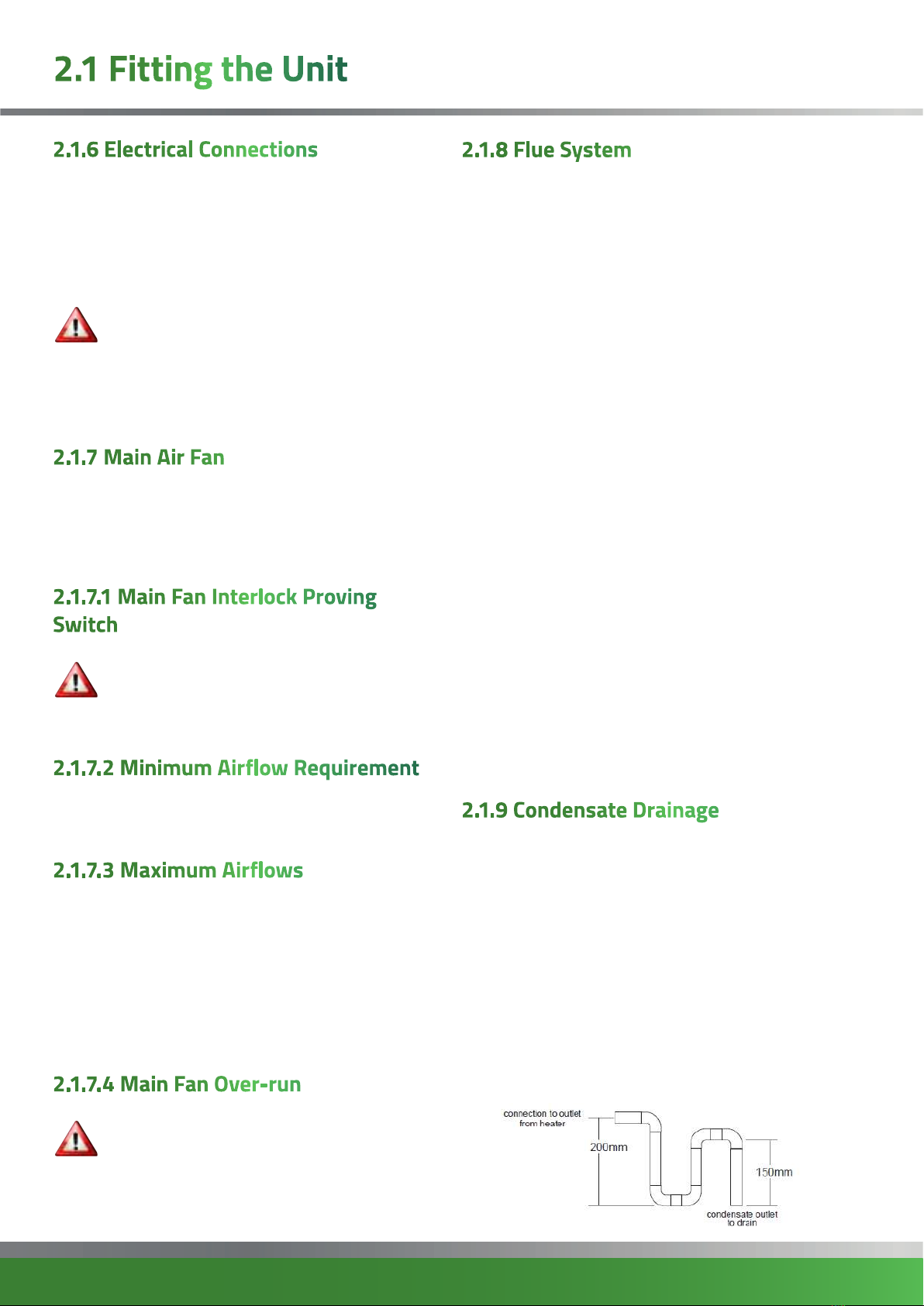
2.1.9CondensateDrainage
If, given the application and usage of the module, it is
considered that condensate will be formed at times then
the condensate drain pipe at the base of the unit must be
fitted with an external trap, equivalent to that shown below,
the outlet of which must be run to a local drain point. The
trap can be a proprietary item or fabricated using standard
domestic 32mm waste water fittings in which case ensure
that the dimensions shown are adhered to.
The trap must be filled with water after installation and
before the heater is commissioned. The trap and associated
pipe work must be protected from freezing. If drainage
under gravity is not possible a condensate pump should be
used and installed following the manufacturers instructions.
2.1 Fitting the Unit
2.1.6ElectricalConnections
Only a suitably qualified operative can complete the
electrical installation and must observe the rules in force.
All electrical connections are made to the screw terminals
in the control section and should be in accordance with
the terminal markings and the wiring diagram for the
module.
Module(s) must be earthed.
A lockout indicator light and reset button are fitted in
the control panel. If required these functions can be
duplicated remotely from the module.
2.1.7 Main Air Fan
The module(s) does not include the main air moving fan.
Direction of airflow may be either R-L or L-R for vertically
orientated modules or from top to bottom or bottom to
top for horizontally orientated units.
2.1.7.1 Main Fan Interlock Proving
Switch
The main fan must be interlocked to the module
by a pressure switch or sail switch or equivalent
so that if the main air flow fails for any reason
the module(s) is shut down.
2.1.7.2MinimumAirflowRequirement
The minimum airflows specified in section 1.2 must not
be reduced.
2.1.7.3 Maximum Airflows
The airflow across the module(s) should be kept at a level
that ensures condensation in the tubes will not occur with
the remainder of the air flow passing through a bypass
section to be mixed with the heated air downstream of
the module(s).
Please contact the Powrmatic office to obtain the
appropriate bypass dimensions to suit the specific heater.
2.1.7.4 Main Fan Over-run
The main fan controls must ensure that when
the module is tuned off, i.e. the heat demand is
satisfied, the main fan continues to run for 3-4
minutes to dissipate the residual heat from the module.
page no. 19 of 44
HEMNVx & HEMSL Range Users, Installation & Servicing Instructions Doc Ref M103 issue 3.6 Mar 2020.
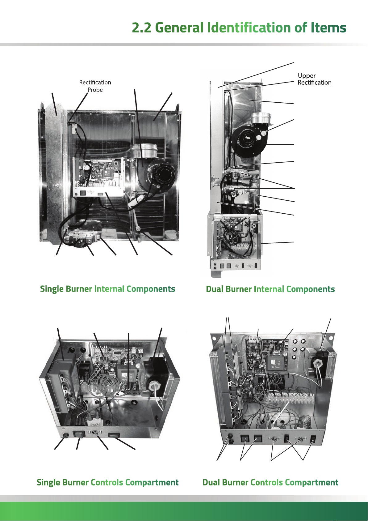
Dual Burner Controls Compartment
Exhaust
Header Box
Upper
Burner Set
Lower
Burner Set
Exhaust Fan
Exhaust Fan Flow
Sensing Point
Gas Valves
Gas Inlet
Controls
Panel
Upper Spark
Ignition Probe
Probe
Limit
Thermostat
Sequence
Controllers Exhaust Fan
APS
Incoming
Electrical
Connection
Point
Limit
Indicators
Lockout
Indicators
Fuses
Burner Set
(behind Heat Shield)
Exhaust Fan Exhaust
Header Box
Spark Ignition
Probe
Gas Valv
Inlet
Control
Panel
Exhaust Fan
Flow Sensing
Point
Sequence
Controller
Exhaust Fan
APS
Limit
Thermostat
Limit
Indicator
Lockout
Indicator
Fuse
eGas
SingleBurnerControlsCompartment
SingleBurnerInternalComponents DualBurnerInternalComponents
2.2GeneralIdentificationofItems
Incoming
Electrical
Connection
Point
Modulating
Interface
Board
(where tted)
Modulating
Interface
Board
(where tted)
page no. 20 of 44 HEMNVx & HEMSL Range Users, Installation & Servicing Instructions Doc Ref M103 issue 3.6 Mar 2020.
Warning: THIS APPLIANCE MUST BE
EARTHED.
Warning: Lockout reset is by a switched
Neutral to the controls in the heater.
Warning: Wiring external to the unit must be
carried out by an appropriately qualified
person to current IEE regulations for
Electrical Installations and any local regulations which
apply. Wiring should be completed in flexible conduit.
The local electrical supply must be run to a point adjacent
to the heater and be suitably terminated to provide an
isolation point that will prevent remote activation of the
unit during servicing.
The local electrical supply conditions must be compatible
with the electrical data given on the appliance data plate.
Wiring should be completed in flexible conduit.
Heaters are for use with 230V, 1N, 50Hz supplies.
The method of connection to the main electricity supply
must:-
- facilitate the complete electrical isolation of the
heater(s) via a suitable fused isolator that will prevent
remote activation of the heater during servicing (see
section 1.2 for ratings).
- be in a readily accessible position adjacent to the
heater(s).
- serve only the heater(s).
- have a contact separation of at least 3mm in all poles.
See section 2.5 or the accompanying wiring diagram for
the heater electrical connections.
Reference must be made to Section 2.4.5 to ascertain
the electrical loading of the unit(s) being installed so that
cables of adequate cross-sectional area are used for
the electrical installation. The length of the conductors
between the cord anchorage and the terminals must be
such that the current carrying conductors become taut
before the earth conductor if the cable or cord slips out
of the cord anchorage. All external controls must be of an
approved type.
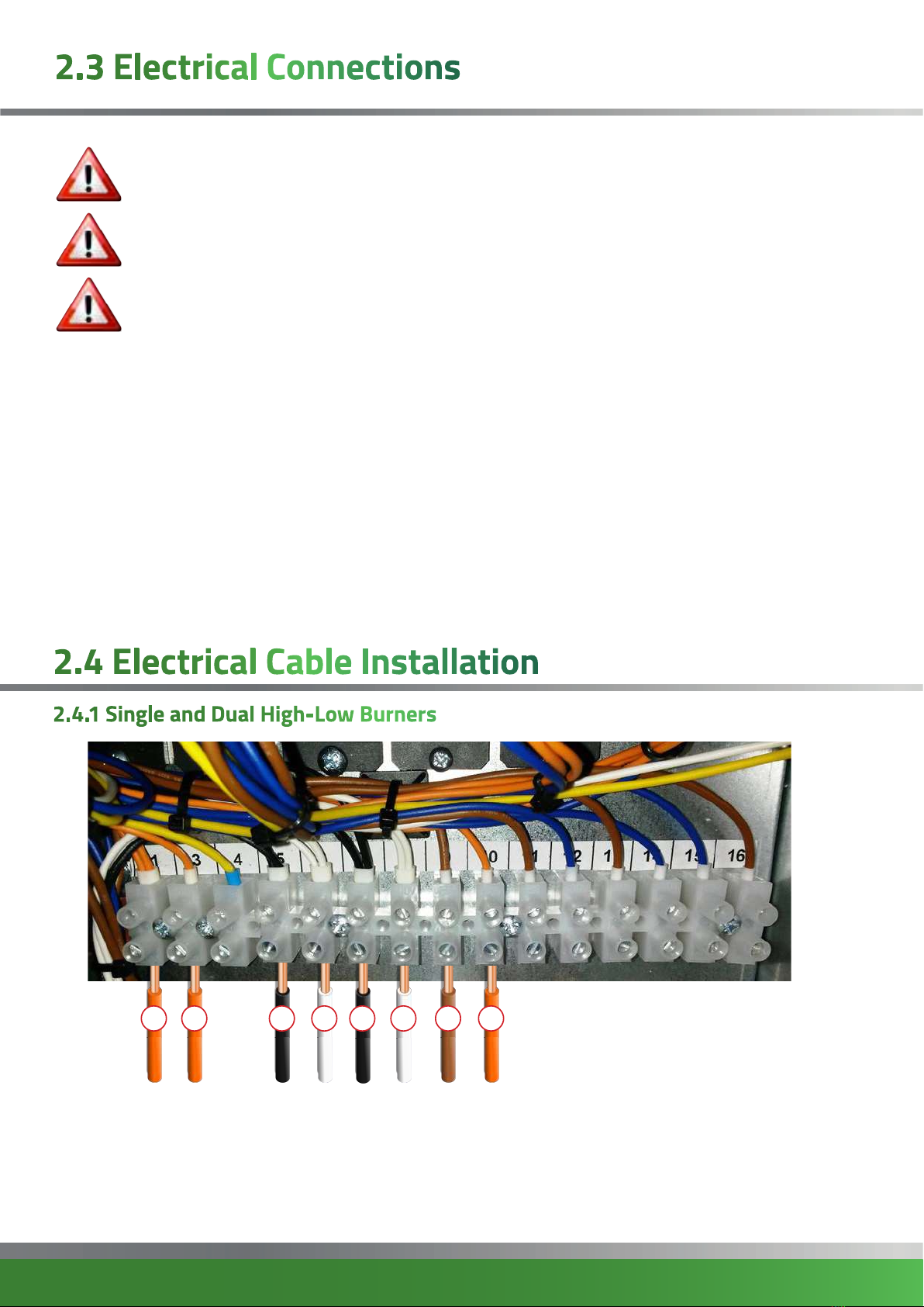
2.4.1 Single and Dual High-Low Burners
* where used
Heat LOW Demand
230V Input
Lockout 1 Indication
230V Output
Lockout 1 Reset
Neutral Input
Main fan
Proving Switch
(suppled by others)
*Heat HIGH Demand
230V Input
*Lockout 2 Indication
230V Output
*Lockout 2 Reset
Neutral Input
t1 t10
t8 t9
t3 t5 t6 t7
2.3ElectricalConnections
2.4ElectricalCableInstallation
This manual suits for next models
27
Table of contents


