manuals.online logo
Brands
  1. Home
  2. •
  3. Brands
  4. •
  5. GE
  6. •
  7. Circuit Breaker
  8. •
  9. GE Power-Break TSUV1 User manual

GE Power-Break TSUV1 User manual

GEH
-
3401
Rev
.
D
vm
IT
V
/
\
7
LinUAi
FIELD
INSTALLABLG
ACCGSSORIGS
UNDERVOLTAGE
RELEASE
DEVICE
\
rUK
ZUUU
-
^
UUUrt
rKHMLi
A
/
UL
Listing
is
voided
when
the
circuit
is
modified
to
add
an
accessory
.
Remove
and
discard
the
UL
!
abe
!
.
INSTALLATION
IMOZO
:
\
A
f
/
1
/
"
J
A
/
i
A
/
«
1
>
1
/
^ ^
<
£
«
«
II
!
M
I
L
.
vv
/
in
/
v
/
/
vc
7
.
vvnen
insicuimy
auuessur
itts
,
iriu
h
m
2
L
-
ar
m
11
of
ha
aa
m
n
I
aialw
Wo
_
nnQi
-
n
/
vnW
onW
uunv
/
:
IMUVJI
I
!
\
s
i
y
I
{
.
.
KsCA
CM
/
V
_
l
disconnected
from
the
electrical
circuit
.
This
is
mandatory
since
breaker
must
be
on
during
certain
stages
of
installation
and
testing
.
ELECTRICAL
DATA
Rated
Voltage
r
\
MA
current
/
on
I
I
“
7
A
Z
"
"
'
\
1
UU
n
/
L
MO
/
A
r
*
MO
nv
/
"
*
OO
/
~
>
_
j
_
M
.
Od
L
.
IMU
.
1
.
Disassemble
the
circuit
breaker
;
see
GEH
-
4382
.
TSUV
1
TSUV
2
TSUV
4
f
TSUV
6
TSUV
7
25
120
V
AC
240
V
AC
480
V
AC
600
V
AC
12
V
DC
A
/
^
«
/
\
1
U
LG
.
Verify
that
circuit
breaker
handie
has
been
r
^
runlsnri
t
\
A
/
Jr
*
ci
h
\
/
3
f r
\
r
\
r r
\
r
'
aarii
nrt
C
/
/
Ul
fc
V
/
IUI
/
A
-
/
O
/
O
/
ly
L
/
UL
/
UU
/
;
/
y
.
111
!
U
A
—
B
25
J
-
25
/
7
25
©
'
2
.
Remove
the
right
-
hand
center
pole
knockout
as
shown
in
Fig
.
2
.
211
A
,
1
n
/
i
I
\
J
~
X
o
/
i
\
/
np
V
L
/
U
TCI
i
\
/
Q
IOUVU
48
V
DC
125
V
DC
250
V
DC
54
TSUV
9
TSUV
10
TSUV
11
t
3
.
Remove
aii
debris
from
inside
breaker
.
Ol
24
24
f
Externally
mounted
dropping
resistor
supplied
with
device
.
\
nn
fP
>
7
U
/
/
X
/
m
/
A
/
\
A
/
\
A
1
/
32
"
MAX
.
FIGURE
2
T
£
GENERAL
DESCRIPTION
LATCH
MOUNTING
SCREWS
-
DIMENSION
SHOWN
SHOULD
NOT
BE
n
EXCEEDED
The
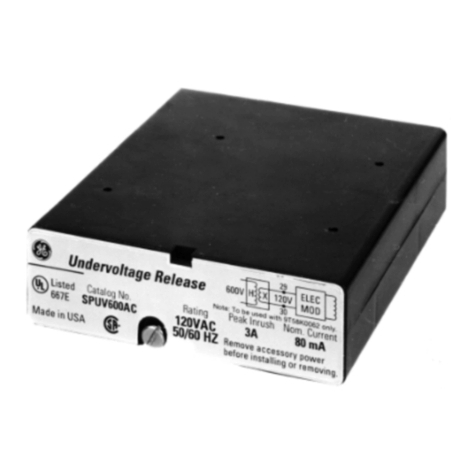
undervoltage
release
device
,
Fig
.
1
,
is
used
to
open
the
circuit
breaker
when
the
supply
voit
-
<
*
*
•
*
3
rr
r
.
'
4
M
tr
«
x
JL
i
«
i
—
_
aye
uiujjb
LVJ
OO
-
UVJ
puruuiiL
ui
mu
raLUU
vuuage
.
n
U
(
Q
)
111
!
s
^
*
^
V
s
<
/
V
“
f
I
r
i i
&
1
S
'
PpH
<
!
m
UK
nniilUi
\
RESETTING
r
*
i
mr
A
r
-
r
\
ovnrHveo
TRIP
SLiDE
Fig
.
1
.
Undervoltage
release
device
Fig
.
2
.
Center
-
pole
knockout
removal
I
H
o
co
mcfnipf
ir
»
n
c
n
A
n
AT
n
nm
AT
1
#
T
A
^
AI
/
A
»
*
AII
A
I
/
P
/
\
p
M
AMI
.
IM
^
^ ^
M
X
~
M
^
^
L
_
_
i
-
-
.
..
i
_
L
_
•
"
v
''
'
x
'
"
.
vi
»
wvi
>
v
>
>
<
#
ww
f
.
wt
^
w
>
^
/
v
«
i
i
•
v
»
ui
MM
u
w
«
MI
i
j
MI
r
ui
luiiuiij
in
CUUIUIIICIII
nui
/
u
ui
uviuc
ivji
cvci
/
UUiJIUlC
LUfll
f f
/
QCflCy
TO
UK
met
in
connection
with
installation
,
operation
or
maintenance
.
Should
further
information
be
desired
or
should
particular
problems
arise
which
are
not
covered
sufficiently
for
the
purchaser
'
s
purposes
,
the
matter
should
be
referred
to
the
General
Electric
Company
.
Courtesy of NationalSwitchgear.com
GEH
-
3401
Rev
.
D
RESETTING
ROLL
PIN
1
/
16
"
to
3
/
32
“
-
n
MOUNTING
1
SCREWS
Fig
.
3
.
View
snowing
mounting
screws
4
.
Place
the
undervoltage
release
device
inside
the
circuit
breaker
mechanism
frame
as
shown
in
Fig
.
3
.
Fig
.
5
.
View
showing
resetting
roll
pin
Note
:
It
is
very
important
to
be
sure
the
resetting
roll
pin
is
beneath
the
resetting
surface
of
the
re
-
setting
lever
.
See
Fig
.
4
.
7
.
Preparing
for
functional
check
:
a
.
For
Manual
Circuit
Breakers
:
Replace
the
breaker
cover
.
b
.
For
Electrical
Circuit
Breakers
:
1
)
Instaii
inner
cover
;
see
GEH
-
4382
.
2
)
Install
outer
cover
.
1
RESETTING
LEVER
*
8
.
Functional
Check
Apply
rated
voltage
to
the
coil
and
close
the
breaker
.
Reduce
the
voltage
to
the
coil
and
verify
that
the
device
drops
out
.
ROLL
PIN
9
.
Reassemble
the
circuit
breaker
;
see
GEH
-
4382
.
*
*
vyV
Fig
.
4
.
Roll
pin
position
10
.
Apply
descriptive
label
to
right
side
of
circuit
breaker
.
5
.
Install
the
mounting
screws
(
two
)
through
the
slots
in
the
mechanism
frame
and
into
the
tap
-
ped
holes
in
the
frame
of
the
undervoltage
re
-
lease
device
.
Position
the
unit
to
provide
1
/
16
-
inch
to
3
/
32
-
inch
gap
,
as
shown
in
Fig
.
5
,
and
torque
the
screws
to
15
inch
-
pounds
.
6
.
Insert
the
leads
through
the
knockout
and
posi
-
tion
them
,
as
shown
in
Fig
.
6
,
with
tape
to
en
-
sure
that
leads
will
not
be
pinched
under
the
breaker
mounting
pads
during
installation
.
Check
the
leads
at
the
undervoltage
release
de
-
vice
to
be
sure
they
do
not
interfere
with
any
moving
parts
.
BREAKER
MOUNTING
PAD
’
7
B
&
W
SasdfeSSv
=
GENERAL
ELECTRIC
CO
.
,
CIRCUIT
PROTECTIVE
DEVICES
DEPARTMENT
,
PLAINVILLE
,
CT
06062
Printed
in
U
.
Jj
.
A
.
M
913
5
/
77
Courtesy of NationalSwitchgear.com

This manual suits for next models

8

Other GE Circuit Breaker manuals

GE Power Break II User manual

GE

GE Power Break II User manual

GE AK-15 User manual

GE

GE AK-15 User manual

GE MicroVersaTrip AKR-75 User manual

GE

GE MicroVersaTrip AKR-75 User manual
GE GE-200A User manual

GE

GE GE-200A User manual

GE AM-13.8-500-7 User manual

GE

GE AM-13.8-500-7 User manual

GE A Series Pro-Stock TQD User manual

GE

GE A Series Pro-Stock TQD User manual

GE AKR-3-50 User manual

GE

GE AKR-3-50 User manual

GE Power Break II User manual

GE

GE Power Break II User manual

GE AK-1-50 User manual

GE

GE AK-1-50 User manual

GE AKR Series Configuration guide

GE

GE AKR Series Configuration guide

GE MicroVersaTrip AK-50 User manual

GE

GE MicroVersaTrip AK-50 User manual

GE MicroVersa Trip Plus User manual

GE

GE MicroVersa Trip Plus User manual

GE Spectra Series User manual

GE

GE Spectra Series User manual

GE AKR User manual

GE

GE AKR User manual

GE Power Break II SPUV012DC User manual

GE

GE Power Break II SPUV012DC User manual

GE AM-13.8-500-5C User manual

GE

GE AM-13.8-500-5C User manual

GE GL 310 F3/4031 P/VR User manual

GE

GE GL 310 F3/4031 P/VR User manual

GE AM-2.4/4.16-100/150- 3 User manual

GE

GE AM-2.4/4.16-100/150- 3 User manual

GE AM-4.16-250-6 User manual

GE

GE AM-4.16-250-6 User manual

GE POWER BREAK MICRO-VERSATRIP E39ME20 User manual

GE

GE POWER BREAK MICRO-VERSATRIP E39ME20 User manual

GE EntelliGuard GT-H User manual

GE

GE EntelliGuard GT-H User manual
GE ReliaGear Pro-Stock Spectra RMS User manual

GE

GE ReliaGear Pro-Stock Spectra RMS User manual

GE GL 310 F1/4031 P/VR User manual

GE

GE GL 310 F1/4031 P/VR User manual

GE PowerVac User manual

GE

GE PowerVac User manual

Popular Circuit Breaker manuals by other brands

Eaton LS-S ZBZ Series operating instructions

Eaton

Eaton LS-S ZBZ Series operating instructions

eMitter DC1600A specification

eMitter

eMitter DC1600A specification

GenInterlock SYL-200 manual

GenInterlock

GenInterlock SYL-200 manual

hager h3 x250 User instructions

hager

hager h3 x250 User instructions

Siemens SIMATIC ET 200SP HA Equipment manual

Siemens

Siemens SIMATIC ET 200SP HA Equipment manual

Doepke DRCBO 4 Hi 1 Installation and operating manual

Doepke

Doepke DRCBO 4 Hi 1 Installation and operating manual

Vertical Power VP-X Pro Installation and operating manual

Vertical Power

Vertical Power VP-X Pro Installation and operating manual

Doepke DRCCB 5 Series Installation and operating instructions

Doepke

Doepke DRCCB 5 Series Installation and operating instructions

Siemens 3WN6 operating instructions

Siemens

Siemens 3WN6 operating instructions

Eaton DIL-11-PI Series Instruction leaflet

Eaton

Eaton DIL-11-PI Series Instruction leaflet

Schrack BES2 Series operating instructions

Schrack

Schrack BES2 Series operating instructions

CHINT NB1-63 Series User instruction

CHINT

CHINT NB1-63 Series User instruction

Gewiss MSX manual

Gewiss

Gewiss MSX manual

Siemens 3AH6 operating instructions

Siemens

Siemens 3AH6 operating instructions

ensto SMARTCLOSER installation manual

ensto

ensto SMARTCLOSER installation manual

Bticino FC80AC quick start guide

Bticino

Bticino FC80AC quick start guide

ABB DEH41820 Installer's instructions

ABB

ABB DEH41820 Installer's instructions

Delixi NAVIGATOR DZ47L Series user manual

Delixi

Delixi NAVIGATOR DZ47L Series user manual

manuals.online logo
manuals.online logoBrands
  • About & Mission
  • Contact us
  • Privacy Policy
  • Terms and Conditions

Copyright 2025 Manuals.Online. All Rights Reserved.