Siemens Energy SB ICCB Instruction Manual

Siemens Energy & Automation, Inc.
Bellefontaine, OH 43311 U.S.A.
Installing Sensitrip
and SB Electronic Trip Units In Zone
Selective Interlocking or ACCESS
Communications Systems
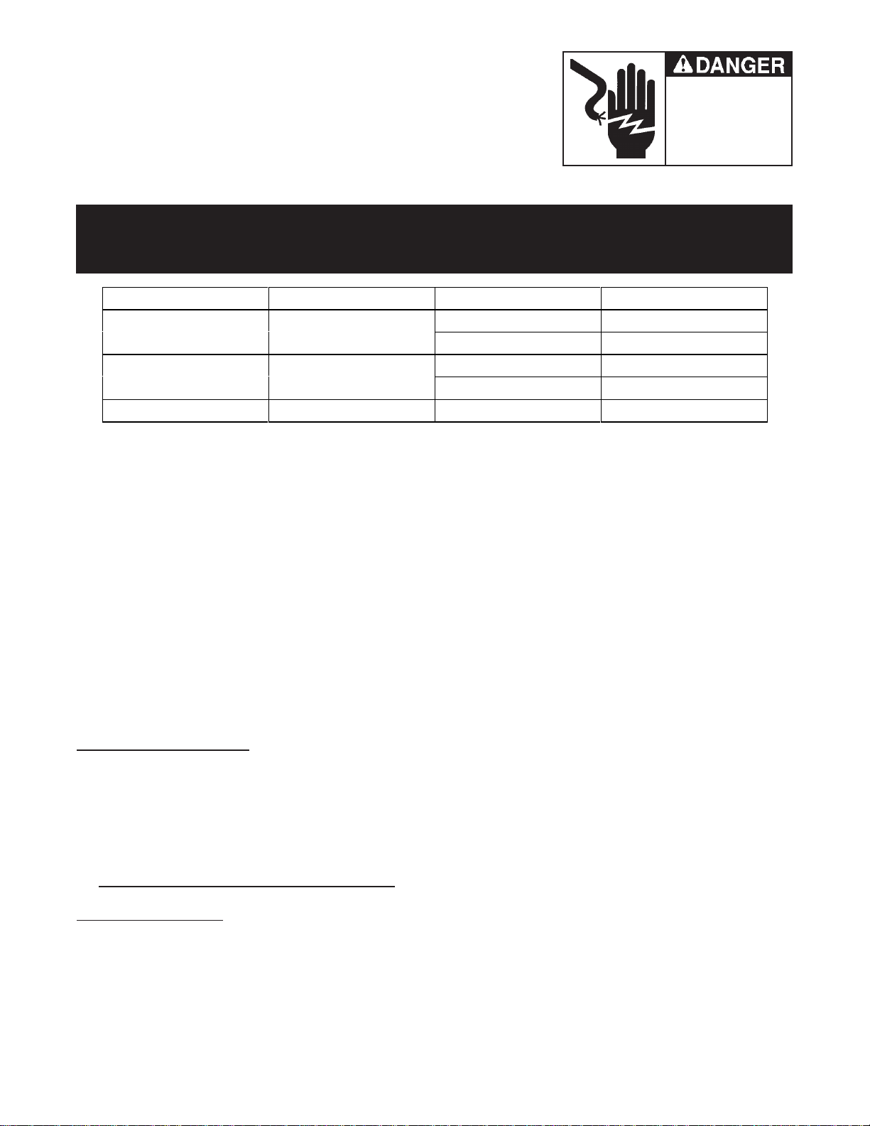
Hazardous voltage.
Will cause death or serious
injury.
Turn off and lock out all power supplying
the circuit breaker prior to cover(s)
removalorwhilecover(s)areremoved
and when installing any internal or
externalaccessory.
Replace the cover(s) and shield(s)
before power supplying this device is
turned on.
Mechanical Hazard.
Mechanism can cause
severe injury when cover is
removed.
Before removing cover
Remove motor fuse
Push open button
Push close button
Push open button again.
Page 1 of 7
Introduction
This Instruction Sheet provides the component selection, cabling and interconnect information to configure
Siemens Sensitrip MCCB and SB Systems Breaker ICCBs in either a Zone Selective Interlocking (ZSI)
network or in an ACCESScommunications system. Installed ICCB SB breakers without communication
capability may be field upgraded by Siemens Field Service personnel only. MCCB breakers may be field
upgraded by Siemens Field Service or the end user. Refer to Figure 1 for a diagram of the possible intercon-
nect schemes described in the following scenarios.
Referenced Publications
The following publications are referenced in this instruction sheet, with the latest versions obtainable through the
local Siemens sales office:
_ACCESSSystems Installation Guide [Manual SG-6028-01]
_Isolated Multi-Drop RS-232 to RS-485 Converter, Operators Manual [Manual SG-6048-01]
_Multiplexer Translator (MT), Information and Instruction Guide [Bulletin 2.21-1A]
_Expansion Plug for Siemens Multiplexer Translator, Information and Instruction Sheet [Bulletin 2.21-2A]
_Electronic Trip Unit for SB Encased Systems Breakers, Information and Instruction Guide [Bulletin 2.20-3A]
_Sentron Systems Breaker, Energy Communicating Trip Unit, Information and Instruction Guide [Bulletin IPIM-
2208]
Referenced Components
The following components are referenced in this instruction sheet, with the latest versions obtainable through the
local Siemens sales office:
•Siemens MTZ (Multiplexer Translator, Zone Interlock) [Cat. No. MTZ] a microprocessor-based device
required for configuring and controlling a Zone Selective Interlocking (ZSI) network of up to eight (8) Sensitrip
or SB circuit breakers; multiple MTs may be interconnected for a total of 31 MTs and 248 breakers.
•Siemens MTA (Multiplexer Translator, ACCESS) [Cat. No. MTA] a microprocessor-based device for config-
uring and controlling up to eight (8) Sensitrip MCCBs and/or SB Trip Units within an ACCESS Communica-
tions System; multiple MTs may be interconnected for a total of 31 MTs and 248 breakers. The MTA also
provides Zone Selective Interlocking capability. Note: the SB-EC trip unit is direct ACCESS compatible but
requires an MTZ or MTA for ZSI capability.
•Siemens type EP (Expansion Plug) - an isolation device to connect Sensitrip MCCBs and SB trip units to an
MTA or MTZ. One (1) per trip unit when required.
Released Production, 2P v1, Jan 13, 2000
Siemens Energy & Automation, Inc.
Bellefontaine, OH 43311 U.S.A.
Page 2 of 7
Hazardous voltage.
Will cause death or serious
injury.
Turn off and lock out all power supplying
thecircuitbreakerpriortocover(s)removal
or while cover(s) are removed and when
installinganyinternalor external accessory.
Replace the cover(s) and shield(s) before
power supplying this device is turned on.
➀Factory wired when ACCESS communications or ZSI is ordered for the SB breaker from the factory.
Breaker Type Frame Size Mounting Type Cat. No.
SB ICCB 1200A, 2000A Fixed EPSBFMK
Drawout EPSBDMK
SB ICCB 3200A, 5000A Fixed EPSB4FMK
Drawout EPSB4DMK
Sensitrip MCCB ALL ALL EP
•Siemens EPC Ribbon Cable [Cat. No. EPC## (where: ## = 08, 12, or 18 inches)] a 16-conductor cable used
to connect the Sensitrip MCCB to an EP; qty. of 1 per trip unit. Order longest standard length when unsure of
application.
•Siemens MTC 4-Wire Telephone Cable [Cat No. MTC## (where: ## = 08, 15, 25 or 50 feet)] a 4-conductor
phone cable, with a male RJ11 connector on each end, to connect an EP to an MT for Sensitrip MCCB applica-
tions or to connect adjacent MTs together. MTC cables may be special ordered in alternate lengths up to 100
feet. Order longest standard length when unsure of application.
•Siemens MTCSB 4-Wire to RJ11 Cable [Cat. No. MTCSB## (where: ## = 8, 15, 25 or 50 feet)] a 4-conductor
phone cable with a male RJ11 connector on one end and 4 spade lugs on the other end; used with SB Trip
Units with rear connected, factory installed EPSB expansion plugs; Used to connect an MT to the factory
installed EPSB expansion plug via the SB breaker secondary terminals or sliding disconnects. MTCSB
cables may be special ordered in alternate lengths up to 100 feet. Order longest standard length when unsure
of application.
•Siemens Isolated Multi-Drop Converter [Cat. No. 18-658-852-537] an optional device used to convert four
(4) RS-485 communications loops to one (1) RS-232 port for host PC communications.
Sensitrip MCCB Breakers
All Siemens Sensitrip Molded Case Circuit Breakers have the capability to function in both a ZSI network and
within an ACCESScommunications system. A separate device, the Siemens Multiplexer Translator, enables
up to eight (8) breakers to communicate in either a ZSI-only scheme (via an MTZ), or in an ACCESScommuni-
cations system (via an MTA) plus ZSI capability. The following scenarios describe the steps and accessories
required to configure these types of systems:
A. Sensitrip MCCB Zone Selective Interlocking (only)
Components Required:
•Siemens MTZ - one per 8 trip units
•Siemens EP expansion plug - one per trip unit
•Siemens type EPC cable - one per trip unit
•Siemens type MTC cable - one per trip unit
➀
➀
➀
➀
Installing Sensitrip
and SB Electronic Trip Units In Zone
Selective Interlocking or ACCESS
Communications Systems
Released Production, 2P v1, Jan 13, 2000

Siemens Energy & Automation, Inc.
Bellefontaine, OH 43311 U.S.A.
Page 3 of 7
Hazardous voltage.
Will cause death or serious
injury.
Turn off and lock out all power supplying
thecircuitbreakerpriortocover(s)removal
or while cover(s) are removed and when
installinganyinternalor external accessory.
Replace the cover(s) and shield(s) before
power supplying this device is turned on.
Installation:
1. Connect an EPC ribbon cable from the front of the Sensitrip Trip Units Test Connector to an EP; note that
the connector is keyed, so that it can only be inserted one way.
2. Based on the sites coordination study, configure the EPs DIP switches for Short Time and/or Ground Fault
ZSI per the EP Information and Instruction Sheet.
3. Connect an MTC cable from the EP to one of eight MTZ communication ports.
4. Configure the MTZs DIP switches to identify the zones for each breaker, per the sites coordination study and
the MTZ instruction sheet.
5. If multiple MTs are used, the Com terminal from the first MTs SEABus Out port must be connected to the
Com terminal of the next MTs SEABus In port on each MT being used.
6. See figure 1 for system connection diagram.
B. Sensitrip MCCB ACCESS Communications (with or without Zone Interlocking)
Components Required:
•Siemens MTA - one per 8 trip units
•Siemens EP expansion plug - one per trip unit
•Siemens type EPC cable - one per trip unit
•Siemens type MTC cable one per trip unit
Installation:
1. Connect an EPC ribbon cable from the front of the Sensitrip Trip Units Test Connector to an EP; note that
the connector is keyed, so that it can only be inserted one way.
2. If ZSI is required, configure per the sites coordination study, and configure the EPs DIP switches for Short
Time and/or Ground Fault ZSI per the EP Information and Instruction Sheet. If ZSI is not required, adjust the
EPs DIP switches to NO ZONE (0000).
3. Connect an MTC cable from the EP to one of eight MTA communication ports.
4. If ZSI functionality is additionally required, per the sites coordination study, configure the MTA to identify the
zones for each breaker according to the MTAs instruction sheet. If multiple MTs are used, the Com termi-
nal from the first MTs SEABus Out port must be connected to the Com terminal of the next MTs SEABus
In port on each MT being used.
5. If ZSI is not required, set the MTAs Device Configuration DIP switches to NO ZONE (00) and the MTAs
Device Type DIP switch to MCCB/ICCB (0001).
6. Connect RS-485 twisted pair communication cable to the MTAs A(+), B(-) terminals and only one end of the
cables shield to the MTs GND terminal. Configure the ACCESS system network, per Installing the ACCESS
System manual. An Isolated Multidrop Converter may be installed as an option. See figure 1 for system
connection diagram.
Installing Sensitrip
and SB Electronic Trip Units In Zone
Selective Interlocking or ACCESS
Communications Systems
Released Production, 2P v1, Jan 13, 2000

Siemens Energy & Automation, Inc.
Bellefontaine, OH 43311 U.S.A.
Page 4 of 7
Hazardous voltage.
Will cause death or serious
injury.
Turn off and lock out all power supplying
thecircuitbreakerpriortocover(s)removal
or while cover(s) are removed and when
installinganyinternalor external accessory.
Replace the cover(s) and shield(s) before
power supplying this device is turned on.
SB System Breakers
The following sections describe both types of SB trip units, the standard Type TL unit with rotary switches, and
the SB Energy-Comm (SB-EC) Trip Unit with keypad and display. Since the SB-EC Trip Unit has integral commu-
nications capability, the MTA device is not required to connect within an ACCESS system, however for SB-EC
Trip Units in a ZSI system, an MTZ or MTA is required.
The type EPSB expansion plug is factory wired to the SB breaker trip units rear connector and also located near
and wired to the SB breakers secondary terminal block for fixed mount breakers or sliding disconnects for
drawout breakers. These connections are factory wired when the SB breaker is ordered with the standard switch
based type TL trip unit for ACCESS communications or for any trip unit with ZSI capability.
Installed ICCB SB breakers without communication capability may be field upgraded for communication capability
by Siemens Field Service personnel only.
The MTCSB cable is used to connect an MTA or MTZ to an EPSB expansion plug via the SB breaker secondary
terminal block or sliding disconnect.
A. SB Breaker Zone Selective Interlocking (only)
1. All SB Breaker Trip Units
Components Required:
•Siemens type MTZ - one per 8 trip units
•Siemens type EPSB expansion plug - one per trip unit, factory wired
•Siemens type MTCSB cable one per trip unit
Installation:
1. When the factory-installed ZSI option is present, the EPSB expansion plug is already wired to the breaker
and secondary control terminals. Connect an MTCSB cables spade lugs from the appropriate SB breakers
secondary terminals (LB9, 10, 11, & 12) to one of eight communication inputs on the MTZ.
2. If multiple MTs are used, the Com terminal from the first MTs SEABus Out port must be connected to the
Com terminal of the next MTs SEABus In port on each MT being used.
3. Based on the sites coordination study, configure the expansion plugs DIP switches for Short Time and/or
Ground Fault ZSI per the EP Information and Instruction Sheet.
4. Configure the MTZ to identify the zones for each breaker, per the sites coordination study and information
and instruction sheet. Refer to figure 1 for system connections diagram.
B. SB Breaker ACCESS Communications (with or without Zone Interlocking)
1. Standard type TL switch-based trip unit
Components Required:
•Siemens type MTA - one per 8 trip units
•Siemens type EPSB expansion plug - one per trip unit, factory wired
•Siemens type MTCSB cable one per trip unit
Installing Sensitrip
and SB Electronic Trip Units In Zone
Selective Interlocking or ACCESS
Communications Systems
Released Production, 2P v1, Jan 13, 2000

Siemens Energy & Automation, Inc.
Bellefontaine, OH 43311 U.S.A.
Page 5 of 7
Hazardous voltage.
Will cause death or serious
injury.
Turn off and lock out all power supplying
thecircuitbreakerpriortocover(s)removal
or while cover(s) are removed and when
installinganyinternalor external accessory.
Replace the cover(s) and shield(s) before
power supplying this device is turned on.
Installation:
1. When the factory-installed ACCESS communications option is present, the EPSB expansion plug is already wired
to the breaker and secondary control terminals. Connect an MTCSB cables spade lugs to the appropriate SB
breakers secondary terminals (LB9, 10, 11, & 12) then to one of eight communication inputs on the MTA.
2. If ZSI functionality is additionally required, per the sites coordination study, configure the expansion plugs
DIP switches for Short Time and/or Ground Fault ZSI per the expansion plugs Information and Instruction
Sheet. Configure the MTA to identify the zones for each breaker, per the sites coordination study and the
MTAs instruction sheet.
3. If multiple MTs are used, the Com terminal from the first MTs SEABus Out port must be connected to the
Com terminal of the next MTs SEABus In port on each MT being used.
4. If ZSI is not required, set the expansion plugs DIP switches to NO ZONE (0000), the MTAs Device Configu-
ration DIP switches to NO ZONE (00) and the Device Type MTAs DIP switch to MCCB/ICCB (0001).
5. Connect RS-485 twisted pair communication cable to the MTAs A(+) and B(-) terminals. Connect only one
end of the cables shield to the MTs GND terminal. Configure the ACCESS system network, per Installing the
ACCESS System manual. An Isolated Multidrop Converter may be installed as an option. See figure 1 for
system connection diagram.
2. SB-EC Trip unit
Since the SB-EC Trip Unit has direct communications with an ACCESS network, no intermediate devices are
required unless ZSI functionality is required.
If ZSI is required, connect as per above using an MTA if type TL SB breaker trip units or Sensitrip MCCB trip
units are part of the overall system and both ACCESS communications and ZSI are required.
Any application requiring only ZSI requires an MTZ configured as above.
If multiple MTs are used for ZSI functionality, the Com terminal from the first MTs SEABus Out port must be
connected to the Com terminal of the next MTs SEABus In port on each MT being used.
As referenced in the SB-EC Trip Unit Information and Instruction Manual, the trip units ACCESS communication
lines are located on the breakers secondary control terminals <LB5> to RS485(+), <LB6> to RS-485(-), and
<LB7> to Shield/Common. Refer to figure 1 for system connection diagram.
Installing Sensitrip
and SB Electronic Trip Units In Zone
Selective Interlocking or ACCESS
Communications Systems
Released Production, 2P v1, Jan 13, 2000

Siemens Energy & Automation, Inc.
Bellefontaine, OH 43311 U.S.A.
Installing Sensitrip
and SB Electronic Trip Units In Zone
Selective Interlocking or ACCESS
Communications Systems
Summary
The following table summarizes the required Component Types per each trip unit in the system. One component
per trip unit unless otherwise noted:
Component Selection Guide ➀
➀When ordered with circuit breaker from the factory.
➁One MTA or MTZ per eight trip units when required.
➂Always required when multiple MTs are used. One additional cable per each additional MT.
Notes:
1. It is recommended that for long, single-ended runs (over 1000 ft.), that a 120 ohm, 1/4 watt terminating
resistor between the Data+ and Data- terminals of the furthest devices be added. Adding a terminator
resistor is not an absolute requirement, but using it will minimize reflected interference on the communication
bus.
2. Both loop and straight RS-485 topologies are acceptable. The advantage of the straight topology is further
distance to the last device (4000 ft.) The advantage to the loop topology is that the devices will continue to
communicate even with a break in the line. The disadvantage of the loop topology is the distance to the
furthest device is only 2000 ft.
3. A Siemens Isolated Multi-Drop Converter [Cat. No. 18-658-852-537] may be used as an optional device used
to convert four (4) RS-485 communications loops to one (1) RS-232 port for host PC communications.
4. Protocol converters are available from the Siemens ACCESS group to provide plug-and-play capability with
over 25 different PLC protocols (Siemens S7, Modbus, etc.), Profibus, DeviceNet, and LonWorks.
5. If multiple MTs are used for ZSI applications, the Com terminal from the first MTs SEABus Out port must
be connected to the Com terminal of the next MTs SEABus In port on each MT being used.
6. Installed ICCB SB breakers without communication capability may be field upgraded by Siemens Field
Service personnel only. MCCB breakers may be field upgraded by Siemens Field Service or the end user.
7. Refer to Installing the ACCESSä System Installation Guide [Manual SG-6028-01] for proper system shield
and grounding connections schemes.
Trip Units and Application
Component
Type
ZSI (only)
with Sensitrip
MCCB’s
ACCESS
and/or ZSI
with Sensitrip
MCCB’s
ZSI (only)
with all
SB-EC
Trip Units
ACCESS
and/or ZSI
with SB-TL
Trip Units
ACCESS
with SB-EC
Trip Units
EP
EPSB
MTZ
MTA
EPC Cable
MTC Cable
MTCSB Cable
➁
➁
➂
✔✔✔✔
✔✔
✔✔
✔✔
✔✔✔✔
Hazardous voltage.
Will cause death or serious
injury.
Turn off and lock out all power supplying
thecircuitbreakerpriortocover(s)removal
or while cover(s) are removed and when
installinganyinternalor external accessory.
Replace the cover(s) and shield(s) before
power supplying this device is turned on.
Page 6 of 7
Released Production, 2P v1, Jan 13, 2000

Siemens Energy & Automation, Inc.
Bellefontaine, OH 43311 U.S.A. Hazardous voltage.
Will cause death or serious
injury.
Turn off and lock out all power supplying
thecircuitbreakerpriortocover(s)removal
or while cover(s) are removed and when
installinganyinternalor external accessory.
Replace the cover(s) and shield(s) before
power supplying this device is turned on.
Pc. No. 411152A02
Page 7 of 7
©Siemens Energy & Automation, Inc. 1999
Installing Sensitrip
and SB Electronic Trip Units In Zone
Selective Interlocking or ACCESS
Communications Systems
Figure 1 - System Connection Diagram
Released Production, 2P v1, Jan 13, 2000
This manual suits for next models
1
Popular Circuit Breaker manuals by other brands


GE
GE AM-13.8-750-4C INSTRUCTIONS AND RECOMMENDED PARTS FOR MAINTENANCE

Siemens
Siemens 3VA9978-0AA Series operating instructions

Siemens
Siemens 3VS16 operating instructions

Eaton
Eaton NZM1-XHB-DA-OAG Instruction leaflet

Mitsubishi
Mitsubishi NF-S Series Technical notes

Green Brook
Green Brook PowerBreaker J62-Y Installation & operating instructions