Powtran PB6012 User manual

Foreword
Thank you for choosing POWTRAN Brake Unit.
This manual provides user the relevant precautions on model
no and specification, installation, wiring, function, routine
maintain, abnormal diagnosis and remove, and how to select
brake resistor etc. The manual can be used for system designer
reference.
In order to ensure correct installation and operation of the
frequency converter, please carefully read this manual before
installing it.
POWTRAN is committed to the continuous improvement of
the product performance, if any change of this information
without prior notice
Powtran
August,2014

Contents
Section I Safety Precautions ...............................................1
Section II Inspection............................................................4
Section III Installation.........................................................5
Section IV Function Parameter Description.....................8
Section V Single Unit Running...........................................9
Section VI Paralleled running ..........................................11
Section VII Fault Diagnosis and Solutions......................13
Section VIII Standard specification.................................14
Section IX Warranty .........................................................17

1
Section I Safety Precautions
Please read the manual before the installation, operation and inspection of
the product. For the safe operation, remind you to pay special attention to the
“Warning” and “Attention” in the manual.
*Attention:
The potential danger will lead to slight or medium life harm or
equipment damage. It could also warn the violate operation.
!Warning:
The potential danger could lead to life harm or private loss!
Statement: When the brake unit is used with other brand
frequency inverter together, our company is only undertake the
product quality problems of 3 packets of responsibility; If the
customer need other projects of joint liability guarantee, Please
cover insurance of the related domestic property insurance company
yourself, In order to obtain relatively good liability to pay
compensation.
*Attention:
*Attention:
●Do not use any brake unit and brake resistor lack of or with
damaged spares.
●Do not touch the internal spares for there are CMOS spares on the
control card of the brake unit. Otherwise it will damage the
spares.
●Please add the fan or other cooling equipment when multiple
brake units installed parallel in the one cabinet.

Section I Safety Precautions
2
*Attention:
*Attention:
* Attention:
!Warning:
●Ensure the right setting of brake unit and brake resistor.
●Do not make voltage resistance test on the brake unit, or it will lead
semiconductor spares damaged in the main circuit of the brake unit.
●Fix the srew when connecting, or the loose connection will lead fire
or creepage.
●Do not touch the brake unit, the internal spares and printing board
after the brake unit is connected, otherwise it will lead to electric
shock. There is high voltage direct current inside.
●Do not touch the heat sink of the brake unit and the brake resistors,
otherwise it will lead to scald or electric shock. There is high
temperature and heated spares inside after the brake unit is connected.
●The brake resistor should be with temperature and other protection.
Because the brake unit is defective when the brake resistor keeps
heated, it should have been isolated itself. Powtran will not take the
responsibility of such accident caused by no automatic isolation.
●The unit and brake resistor should be installed on the medium
with flame retardancy.
●Connection is allowed only when the power is switched off
and completely out of power.
●Only well-trained personnel are allowed to use this unit.
4

Section I Safety Precautions
3
!Warning:
!Warning:
!Warning:
!Warning:
●Ensure the correct connection before running.
●Ensure the right host and slave selection and voltage class before
running.
●Only when the charge light is off and ensure the charge voltage is
0 with the multimeter, the brake unit could be adjusted and
repaired.
●During the running, do not touch any spares inside.
●Please refer to the content in the manual when analyze and
manage the fault of the brake unit. Any modification to the brake
unit is not allowed otherwise the life harm and property loses will
not be burdened by Powtran.
●This product is the accessories of the inverter, if it is used
improperly which would not only do damage to itself but also to
the inverter. Please pay much attention to this.

4
Section II Inspection
Powtran Brake Unit has been tested and inspected before leaving the
manufacturer. Before unpacking the product, please check if the package is
damaged due to careless transportation, and if the specifications and type of the
product complies with the order. Please contact the supplier of Powtran
products if any problems are found.
Only the well-trained personnel are allowed to use this
unit, and such personnel must read through the parts of this
manual relating to the safety, installation, operation and
maintenance before using the unit. The safe operation of this
unit depends on correct transport, installation, operation and
maintenance.

5
Section III Installation
3-1.Conditions for Use
Hangging Brake unit should be installed inside the house where is
ventilative.
Ambient condition should accord with the followings:
(1).Environmental temperature -10℃to 50℃Above 40℃,the capacity will
decrease 3% by each 1℃.So it is not advisable to use inverter above 50℃
(2).Preventing electromagnetic interference, away from the interference so
urces
(3).Prevent dropping dust, powder, cotton fiber or fine metal powder from
entering it.
(4).Prevent oil, salt and corrosive gas from entering it.
(5).Avoid vibration.
(6).Avoid high temperature and moisture and avoid being wetted due to raining,
with the humidity below 90%RH (not dewing).
(7).Prohibit the use in the dangerous environment where inflammable or
combustible or explosive gas, liquid or solid exists.
3-2.Sharp size
(A)PB6012/PB6014
8

Section III Installation
6
(B)PB6022/PB6024
(C) PB6032/PB6034
3-3.Main circuit specification:

Section III Installation
7
Connection diagram of Brake unit and Inverter
*NOTE:
(1) Cable length of the frequency converter and braking unit is less than
5 m
(2) Cable length of the Braking resistor (Rb) and brake unit is less than
10 m, and must use heat-resisting conductors
(3) P, N is the terminal "+""-" of the frequency inverter dc bus, P is the
positive terminal, e, N is a negative terminal "-"
(4) P, N line must be twisted together, Rb and Rb ' line must be twisted
together..
!Warning:Incorrect connection of the main circuit will lead the
damage to the brake unit and inverter.
8
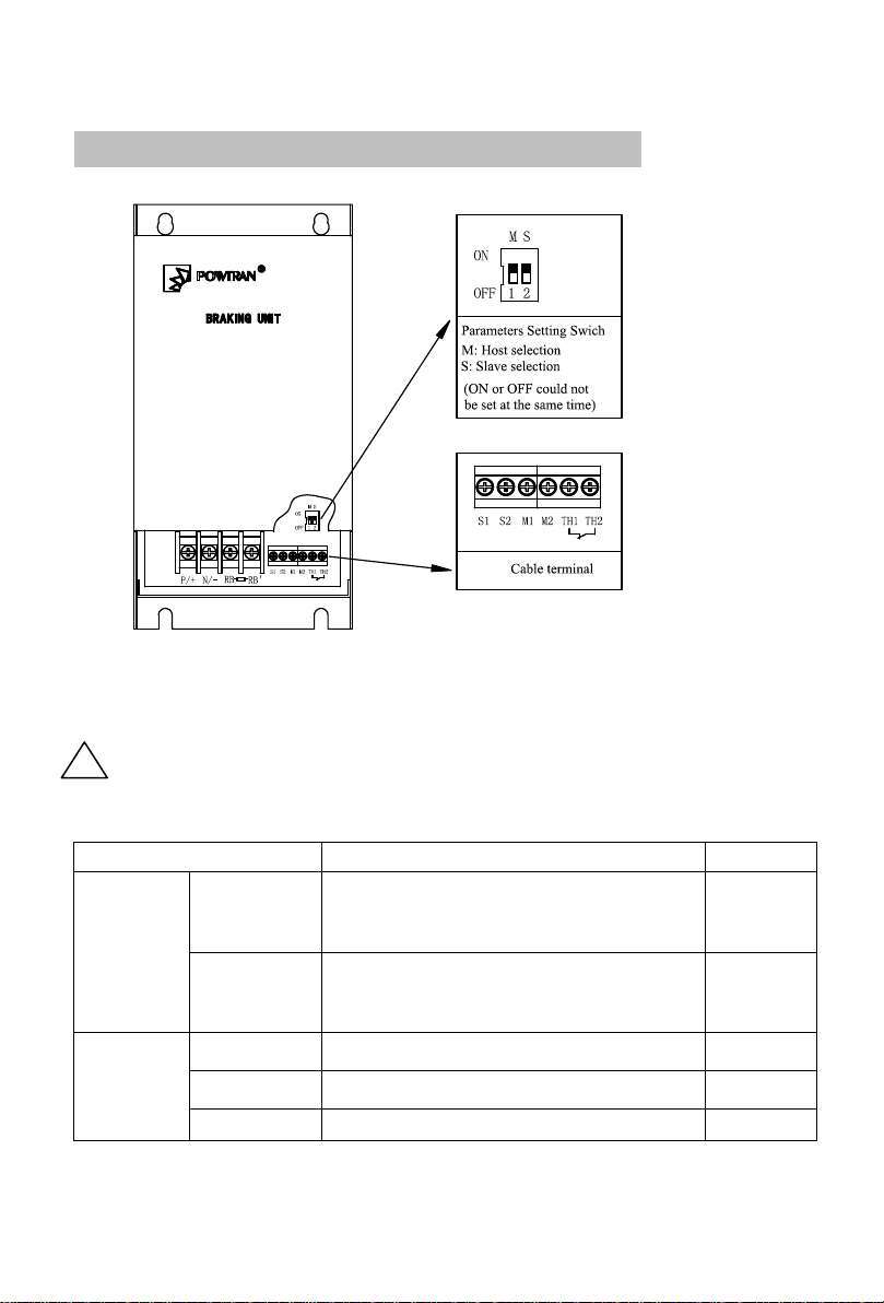
Section IV Function Parameter Description
Parameter setting switch and control terminal
Note:Only PB6032,PB6034 have M,S slave and host selection,but other type
no. The voltage class is set OK during the factory setting.
!Warning:Incorrect selection of the slave and host will lead
abnormal running and damage!
Description of control circuit terminal of the brake unit
Terminal
Specification
Note
Parameter
Setting
switch
1
Slave and host selection switch, when
M is ON, the brake unit is set to be
host brake unit
Factory
setting:O
N
2
Slave and host selection switch, when
S is ON, the brake unit is set to be
slave brake unit.
Factory
setting:O
FF
Control
M1/M2
Slave and host control terminal
S1/S2
Slave and host control terminal
TH1/TH2
OH protection switch(always close)
9
14

9
Section V Single Unit Running
Connection diagram of single brake unit and inverter
When 1 unit is used, please refer to the above diagram, connect the
inverter, brake unit and brake resistor and run it.
200V grade
Voltage
selection
the input power supply
voltage of the
frequency inverter
Brake starting voltage (PN
voltage)
220V
220VAC
365VDC±3%
400V grade
Voltage
selection
the input power supply
voltage of the
frequency inverter
Brake starting voltage (PN
voltage)
380V
380VAC~415VAC
690VDC±3%
* NOTE:
(1) if the grid voltage 20% higher than the normal voltage supply, please set the
larger voltage.
12

Section V Single Unit running
10
(2) please confirm starting braking voltage macth the device .
!Warning: in the CHARGE indicating lamp before fully
extinguished (there is voltage between PN) not allowed to adjust
the settings!
16
9
14

11
Section VI Paralleled running
Diagram of the connection of paralleled running brake unit and inverter
(Only PB6032,PB6034 with this function)
If 2 or more over brake units are paralleled, please refer to the above
diagram and connect the inverters, multiple brake units and brake resistors.
6-1、Host and slave select of function setting
(1) The factory setting of the brake unit is set to be the host (M), do not
modify the factory setting if only one brake unit is used.
(2) When 2 or more over brake units are paralleled, the control terminal
(S) is used. Please refer to the “Host and slave control connection”.
6-2、Host and slave control connection
(1) The brake unit has host/slave switch. Set the brake unit 1 to be “M”,
the brake unit 2 and 3 to be “S”
(2) Connect separately M1, M2 of the brake unit 1 with S1, S2 of the
brake unit 2;
Connect separately M1, M2 of the brake unit 2 with S1, S2 of the

Section VI Paralleled running
12
brake unit 3. Etc.
*Note:
Double wind the M1, M2 and S1, S2, and please make it as short as you
can; the maximum paralleled brake units is only 10.
16

13
Section VII Fault Diagnosis and Solutions
NO.
Fault state
Reason
Processing
method
1
The brake
resistor
heated badly
when it
brakes.
Main circuit power IGBT of
the unit short circuit
Change brake
unit
Incorrect selection of the brake
unit voltage
Choose suit
voltage brake
unit
Brake unit faulted
Change brake
unit
2
Inverter OU
Lack of braking of the brake
resistor
check the brake
condition
Not suited brake unit voltage
braking unit
voltage too high
Brake unit faulted
Change brake
unit
3
relay action
over heat
protection
Heat sink temperature over
80℃
Braking rate is
too high, forced
air cooling
*NOTE:
The electric net voltage is too high, please select the high voltage
setting.
!Warning:Open the P and N, ensure there is no voltage
between PN when use and inspect the unit! This unit
control circuit is not isolated circuit.

14
Section VIII Standard specification
8-1、Model specification:
200V level(200/220/240V)
Type
Sharp size
Allowed max. brake current (65℃)*
PB6012
A
40A
PB6022
B
70A
PB6032
B
140A
400V level(380/415V)
Type
Sharp size
Allowed max. brake current (65℃)*
PB6014
A
40A
PB6024
B
70A
PB6034
B
140A
*NOTE:
The allowed maximum current of the power spares IGBT inside the brake
unit with the certain temperature.
8-2、Model designation:
e.g.:
6: Design Series No.
01/02/03: Capacity No.
2: 200V 4:400V
PB: Powtran Brake Unit

Section VIII Standard Specification
15
8-3、200V specification and selection reference:
Capacity no.
HP(kW)
Brake Unit
Brake resistor(150% brake
torque)
Type
Qty(pc)
Type
Qty(pc)
7.5(5.5)
PB6012
1
30Ω/520W
1
10(7.5)
1
20Ω/780W
1
15(11)
1
13.6Ω/2400W
1
20(15)
1
10Ω/3000W
1
25(18.5)
PB6022
1
8Ω/4800W
1
30(22)
1
6.8Ω/4800W
1
40(30)
1
5Ω/6000W
1
50(37)
1
5Ω/6000W
1
60(45)
PB6032
1
3.4Ω/9600W
1
75(55)
1
3.4Ω/9600W
1
100(75)
PB6032
2
5Ω/6000W
2
125(93)
PB6032
3
5Ω/6000W
3
150(110)
3
5Ω/6000W
3
8-4、400V specification and selection reference:
Capacity no.
HP(kW)
Brake Unit
Brake resistor(150% brake
torque)
Type
Qty(pc)
Type
Qty(pc)
7.5(5.5)
PB6014
1
75Ω/780W
1
10(7.5)
1
50Ω/1040W
1
15(11)
1
50Ω/1040W
1
20(15)
1
40Ω/1560W
1
25(18.5)
1
32Ω/4800W
1
30(22)
1
27.2Ω/4800W
1
40(30)
PB6024
1
20Ω/6000W
1
50(37)
1
16Ω/9600W
1
60(45)
1
13.6Ω/9600W
1
75(55)
1
10Ω/12000W
1
100(75)
PB6034
1
6.8Ω/12000W
1
125(93)
1
6.8Ω/12000W
1

Section VIII Standard Specification
16
150(110)
1
6.8Ω/12000W
1
175(132)
PB6034
2
6.8Ω/12000W
2
200(160)
2
6.8Ω/12000W
2
250(187)
PB6034
3
6.8Ω/12000W
3
300(220)
3
6.8Ω/12000W
3
8-5、Brake resistor selection:
(1) The best braking resistance with no sense of resistance, in order to
reduce the inductance.
(2) Braking resistor grounded is strictly prohibited, otherwise it will lead
the serious damage to the unit and inverter
(3) Selection of the brake resistor capacity is for reference, it depends on
the load intertia, brake frequency, etc characteristic. Please inquire
Powtran when you have questions
*NOTE:
(1) Parallel braking unit can improve the braking capability.
(2) Braking ability of 2 sets brake unit parallel is 2 times for single one.
Example: PB6032= PB6022×2 = PB6012×4.

17
Section IX Warranty
The product quality shall comply with the following provisions:
1. Warranty terms
1-1. The product from the user the date of purchase, the warranty period
of 12 months (limited to domestic market).
1-2. Export products and non-standard products warranty period is 12
months or according to the agreement of warranty execution.
1-3. The product from the user the purchase date, guarantee to return,
replacement, repair service, within one month after the date of shipment.
1-4. The product from the user the date of purchase, replacement, repair
within three months after the date of shipment.
1-5. The product from the user the purchase date, enjoy lifelong
compensable service.
2. Exceptions clause
If belongs to the quality problems caused by following reasons products,
not within the warranty.
2-1. The user is not in accordance with the "products manual" is used
method of operation caused the failure.
2-2. Users without permission to repair or alteration caused by product
failure.
2-3. Users beyond the standard specifications require the use of the
inverter caused by product failure.
2-4. Users to buy and then fell loss or damage caused by improper
handling.
2-5. Because the user use environment device caused by aging lead to
product failure.
2-6. Due to the fault cause of earthquake, fire, lightning, wind or water
disaster, abnormal voltage irresistible natural disasters.
2-7. Damaged during shipping (Note: the transport mode specified by
the customer, the company to assist to handle cargo transfer procedures).
3. The following conditions, manufacturers have the right not to be
warranty
3-1. No product nameplate or product nameplate blurred beyond
recognition.
3-2. Not according to the purchase contract agreement to pay the
money.
3-3. For installation, wiring, operation, maintenance and other users can
not describe the objective reality to the company's technical service center.
4. In return, replacement, repair service, shall be returned the company,
confirmed the attribution of responsibility, can be returned or repair
This manual suits for next models
5
Table of contents
Other Powtran Circuit Breaker manuals

Popular Circuit Breaker manuals by other brands


Siemens
Siemens NXPLUS C Installation and operating instructions

Delixi
Delixi NAVIGATOR DZ47L Series user manual

TEL
TEL TAVRIDA ELECTRIC VCB15 LD user guide

ABB
ABB HD4/R Installation and operating instructions

CHNT Power
CHNT Power Smart Meter CPS1000 user manual

Eaton
Eaton Cutler-Hammer Digitrip RMS 810 instructions