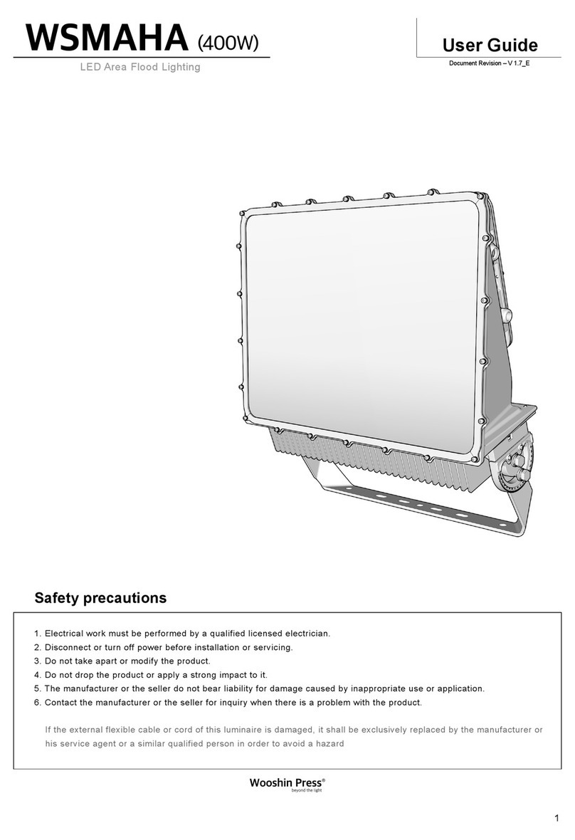
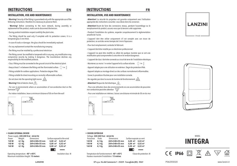
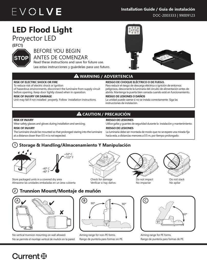
PR XR230 BEAM User manual

2
INDEX
1. SAFETYAND WARNINGS ……………………………………………………………………………………… 3
2.
3.
INSTRUCTIONS……………………………………………………………………………………………………
APPEARANCE ……………………………………………………………………………………………………
4
5
4. INSTALLATION…………………………………………………………………………………………………… 5
5. SETUP AND CONFIGURATION…………………………………………………………………………………… 9
6. OPERATION MENU………………………………………………………………………………………………… 12
7. DMX PROTOCOL………………………………………………………………………………………………… 13
8. ERROR MESSAGES ……………………………………………………………………………………………… 16
9. TECHNICAL DATA………………………………………………………………………………………………… 16
10. CIRCUIT DIAGRAM AND PCB CONNECTIONS………………………………………………………………… 19
11. COMPONENT ORDER CODES…………………………………………………………………………………… 21
ACCESSORIES
The following items are supplied with the projector and please check:
Name
Quantity
Unit
Remark
Safety cord
1
Pc
Clamp
2
Pc
Foldable clamp
2
Pc
Optional
User manual
0
Pc
QR code
Please note that as part of our ongoing commitment to continuous product development, specifications are subject to change
without notice. Whilst every care is taken in the preparation of the manual we reserve the right to change specifications in the
course of product improvement. The publishers cannot be held responsible for the accuracy of the information herein, or any
consequence arising from them.
Every unit is tested completely and packed properly by the manufacturer. Please make sure the packing and / or the unit are in
good condition before installation and use. Should there be any damage caused by transportation, consult your dealer and do not
use the unit. Any damage caused by improper use will not be assumed by the manufacturer and / or dealer.
Any future technical change in the user manual won’t be with any notice.
Note: For the products made by Guangzhou PR lighting Ltd, the warranty for the whole product is one year starting from the
delivery date but the light source is not within the warranty

3
1. SAFETY AND WARNINGS
NOTE
Before a projector’s installation, power-on, operation and maintenance, please carefully read
the safety information hereinafter!
The following safety signs are used in the user manual.
Warning
User
Manual
Electrical
shock
Goggles
Protective
Gloves
Flames
High
Temperature
● When unpacking, check if there is transportation damage before using a projector. Should there be any damage
caused by transportation, consult your dealer and do not use it.
●The manufacturer is not responsible for any loss caused by the user not following the manual or changing a
projector as he/she likes.
●Please be noted that the damage caused by changing a projector at will is not warranted.
● Do not hesitate to contact the dealer or the manufacturer if any questions or advice.
● If a lamp is deformed by heat or damaged , please replace it with a new one.
● A projector with IP20 can only be used indoors.
●For a projector with IP20, keep it away from rain and moisture, excessive heat, humidity and dust. Do not allow
its contact with water or any other liquids.
●A projector should be kept away from high temperature, fire, electrical surge, vibration and strong light while
running.
●.Any maintenance and repair of a projector shouldn’t be carried out by a user and the user shouldn't open it for
any repair work.
●Don’t look straightly into the light sources especially for epileptics, otherwise eyes will be burned.
●Do not connect a projector to any type of dimmer pack.
●If the lamp, lens and screen protective cover of the a projector have obvious damage, i.e., to the extent that it
hurts the performance like cracking or deformation. Please stop using it and replace them with the original parts,
otherwise its performance will be compromised.
● For the installation location of a projector, it shouldn’t be seen in the distance of less than 4 meters for a long
time.
●Before operation, please confirm that all covers (housing) are on and screws tightened. It’s forbidden to use a
projector while covers (housing)are off .
●Keep the lamp clean and do not touch it with bare hands.
●While operating it, wear protective items like eye goggles , gloves and etc..
●Any electrical connection must be carried out by a qualified person .
●Before installation, please confirm the voltage supplied matches what is required for a projector.
●Each projector must be properly earthed and installed as per related electrical standards.
●Do not use power cord with its insulator damaged and connect the power cord with other cables.
●If a projector is not used or under cleaning,, please hold the plug and unplug it. Do not unplug it forcefully or by
pulling the power cable.
●All power cords must conform to related safety and regulations.
●If a projector is not water and dust proof, while being operated it should not be under rains or in humidity to

4
avoid short circuit.
●Do not switch on and off a projector constantly in very short intervals, otherwise the light source’s and other
electrical parts’ life will be shortened .
●There are safety cord holes at the bottom of the base of a projector. In view of safety, please run the safety cord
supplied through the safety cord holes for safety support.
●Before any installation, maintenance and cleaning work, please ensure a projector is disconnected from power
mains.
●After stable operation under normal situation , its temperature is 80℃.
●While the lamp is stricken for the first time, there will be smoke and strange smell. It’s normal and does not
mean a projector has some defects.
●While it running, don’t touch the metal housing to avoid being burned!
●Do not mount a projector directly on inflammable surface.
●Do not project the beam straightly on combustible items and the minimum distance between a
projector
and illuminated items is 5m.
●A projector should be installed with good ventilation and the minimum distance between a projector and a wall
is 50cm. At the same time, please ensure the fans and air inlets and outlets are workable.
●Do not let the front lens under sunlight or other strong light sources at any angle, otherwise the danger of fire
can be caused by the focused beam by the lens inside a projector.
●The product meets The General Technical Requirements and Standards for Recycle and Use Of Expired
Appliance and Electronic Products.
●When the product meets disposal standards and needs to be disposed, a client needs to dispose and recycle it.
2. INSTRUCTIONS
●CLEANING AND MAINTENANCE
Keeping a projector is necessary and the dust, oil and smoke should not accumulate on or in it, otherwise its light output will be greatly
compromised. Regular cleaning will ensure light output at maximum and reliable running during its whole life span. It’s advised to use
soft cloth with good quality detergent. Under whatever circumstances, it should not use alcohol or other solvent.
For the accumulation of oil and smoke on the front lens, thus sharp decrease in light output, the front lens should be cleaned once every
week. Cooling fans cleaned once every month. Internal items inside the projector should be cleaned once every year using vacuum or
blower. Color filters, rotators and internal mirrors should be cleaned once every month.
Regular inspection of air filters and clean them before they fully blocked. Clean air filters at the bottom of the base. Please vacuum or
compressed air to clean and put them back after cleaning.
●Before any maintenance and cleaning, please ensure the project is off the power
●Only qualified person is allowed to do maintenance
●During maintenance and before maintenance, the projector must be off power.
●To avoid internal damage, sun light or other light mustn’t penetrate into the projector via front lens whether
it runs or not
●Do not use alcohol or other organic solvent to clean the housing to avoid damage.
●Do not use any solvent with chemical elements to clean color filters or hot mirror.
. Hot mirror should be cleaned every 3 days and coated with

5
●LUBRICATION
To ensure smooth movement of gobos and zoom and focus lens, it’s advised rotators’ bearings and 2 sliding bars for zoom and focus
lens be lubricated every 2 months. High quality and high temperature lubricant/grease is advised..
●TROUBLESHOOTING
PROBLEM ACTION
The projector doesn’t switch on
Check the fuse on the power socket.
Check the lamp.
The lamp is on but the projector doesn’t respond
to the controller
Make sure that the fixture’s start address is right
Replace or repair the XLR signal cable.
The projector functions intermittently
Make sure the fan is working well or fans and their shields are not blocked
Beam appears dim, Low in brightness
Make sure the lamp is within its lifespan
Remove dust or grease from the lenses.
The project image appears to have a halo
Carefully clean the lamp, optical lenses and other components.
Heavily Defective Beam
Check if lens are in good condition(not cracked)
Clean dust or grease on the lens.
3. APPEARANCE
4. INSTALLATION
A projector can be placed on the stage floor directly or mounted on a truss at any direction without impacting its performance. Please
use a safety cord, which can support 10 times the weight of the projector, while mounting it on the truss. The safety cord should be
used with magazine with a lock. Just as the figures below, please run the safety cord through the holes at the bottom of the base and
around the truss.
● RIGGING
1. Use M12 bolt to fix the clamp(1) into the omega holder (3), run the bolt through the holder’s holes
2. Push 2 quick-lock fasteners(4) into holes at the bottom of the base, fix them and tighten them clockwise
3.Run safety cord(2) through holes at the bottom of the base and around the truss(6)
Arm
Base
Body

6
Use fixing devices like spanner for safe installation.
Note:
1. the distance between the foot
of the base and the front lens
cover(the head facing
downward)
2. the
distance between
mounting truss and the front
lens cover( the head facing
downward)
3. The maximum diameter of
the rotating head ( minimum
spacing between fixtures)

7
WARNING:
●The projector MUST be lifted or carried by the HANDLES instead of clamps.
●.For safety the safety cord should afford 10 times the Projector’s weight.
It must use secondary safety accessory like appropriate net. The structures of the secondary accessory must ensure that while
malfunction happens, the installed parts won’t fall to the ground.
While rigging, mounting or maintaining, the projector mustn’t be placed in the areas listed hereinafter: the bridge, high work areas
or other dangerous areas.
The operator of the projector or its related safety items must be accepted by safety experts before first launching or re-running after
any replacements or repairing.
The operator must ensure a test before acceptance every 4 years and the related safety measures and installation accepted by
experts.
The operator must ensure the related safety measures and its installation must be approved by the technicians every year. The
projector may be installed in places under which people may walk by or sit. Important! Installations in high places requires wide
experience, including but not limited to load limit calculation, the installing materials needed and regular inspection of installing
materials and the projectors. If lacking the qualifications, please don’t try installation by yourself, but seek help from professionals
using designated lifting gears. Abnormal installation may cause body harm or property damages.
The projectors must be installed in places where people can’t reach. If they are removed from ceiling or high places, professional
truss must be used. It is forbidden to let any projector move freely in a room after installation.
Note: Device falling down can cause heavy body harm! If you have any questions about its safety, don’t install any projector!
Before installation, please ensure mounting areas can endure 10 times the weight of a project at least.
●POWER CONNECTION
Connect the power cord as follows:
L (live) =brown
E (earth) =yellow/green
N (neutral) =blue
Before power connection, please ensure the power supplied must match what the nameplate says. It is recommended that each
projector be connected with power separately so that they may be individually switched on and off.
●The earth wire(yellow/green) must be connected to the ground. And electrical connection
must be in accordance with the standards concerned.
●If any questions about the electrical installation, do not continue but consult a qualified
electrician.
●DMX CONTROL CONNECTION
Connection between controller and projector and between one projector and another must be made with a twin-screened cable, with each
wire having at least a 0.5mm in diameter. Connection to and from the projector is via cannon 5 pin (which are included with the projector)
or 5 pin XLR plugs and sockets. The XLR's are connected as shown in the figure above.
4N/C
N/C
5
PIN FUNCTION
GND
1
3DATA+
DATA-
2
DMX 512
DMX IN
DMX OUT
1
2
3
4
55
4
3
2
1

8
Note: care should be taken to ensure that none of the pins touch the metallic body of the plug or each other. XLR plugs and sockets mustn’t
be connected in any way other than mentioned in the above figure. The XR330BWS accepts digital control signals in protocol DMX512
(1990).
Connect the controller’s DMX output to the first fixture’s DMX input, and connect the first fixture’s DMX output to the second fixture’s
DMX input and connect the rest fixtures in the same way. Eventually connect the last fixture’s DMX output to a DMX terminator as shown
in the figure below.
●DMX TERMINATOR
In the Controller mode, at the last fixture in the chain, the DMX output has to be connected with a DMX terminator. This prevents electrical
noise from disturbing and corrupting the DMX control signals.
The DMX terminator is simply an XLR connector with a 120Ω(ohm) resistor connected across pins 2 and 3, which is then plugged into
the output socket on the last projector in the chain. The connections are illustrated below.
●ADJUSTMENT/INSTALLATION/REPLACEMENT OF A LAMP
The procedures for the replacement/adjustment of a lamp
1. Select LAMP OFF under the menu after a fixture is on mains power. Then shut it off from the mains power
2. Loosen 8 screws of the plastic cover
3. Loosen 4 screws of the fan frame, unplug the fan and remove the module
4. Push the upper lamp clipping plate making the spring contract, at the same time push the lamp towards the opposite direction
till it is off the plate. At last remove the lamp obliquely.
5. The installation of the lamp is like its removal

9
6. After the lamp is in the right position, install the fan module, fix it using screws, plug the fan with fan wires, check if the lamp
wires are plugged properly and strike the lamp at last.
7. After lamp on, focus a gobo well. If the light spot is not centered, use flat screwdriver to adjust the lamp’s adjusting screws
8. After lamp adjustment, set LAMP OFF under menu. Shut the fixture off the main power and fix the plastic cover to complete
it.
5. SETUPAND CONFIGURATION
●FRONT PANEL OPERATION
DMX ADDRESS CODE SETTINGS: Set the DMX address(划强调线部分需要与灯具实际英文菜单比对)
CHANNEL MODE: Set DMX channel mode. The numbers stipulated in the menu options mean DMX Channel Number.
RESET: Reset motors
MOTOR POWER:If ON selected, all motors are off power, otherwise all motors will be re-powered and reset. The submenu
is used to re-power and reset motors after re-plugged without mains power being shut off.
PAN TILT : Reset Pan and Tilt motors
………..
RUN:Set running mode
Functions for all submenus are as follows (Note: AUTO mode differs in functions between different products)
DMX :Running via DMX 512 controller
AUTO(Factory test) : Running via programs set by the factory and for factory test
USER : running via programs made by the user. Edit scenes via SELF PROGRAM under RUN SETTINGS
LAMP : Turn on or turn off the lamp. After the value changed, it takes about 3s to execute it. The operation can be canceled via getting the
value back to the original within 3s. After the lamp-off, it must wait between 1 and 2 minutes to re-strike the lamp. If the lamp is
re- stricken within 2minutes, the lamp won’t be on. After 2 minutes lapse, the lamp will be on automatically.
If ON selected, after mains power on, the system will try to strike the lamp.
MANUAL :Set DMX channel values manually
CHANNEL 1 : Set its DMX value
CHANNEL 2: Set its DMX value
CHANNEL 3: Set its DMX value
………..
RUNNING SETTINGS : Set running parameters
MASTER/SLAVE MODE : Set master/slave mode
PAN/TILT SETTINGS :
X REVERSE : If “Y” selected, reverse the rotating direction of the pan motor, otherwise the default.
Y REVERSE : If “Y” selected, reverse the rotating direction of the pan motor, otherwise the default.
X SETTINGS:
STA RT FROM 0-254
FINISH AT 0-255
Y SETTINGS:
STA RT FROM 0-254
FINISH AT 0-255
LINEAR COLOR: If “Y” selected, color wheel moves linearly

10
DIMMER CURVE: Options for dimmer curves( specially for LED fixtures)
SELF PROGRAM:
STEPS
DMX 512 signal detected, it runs in this way.
POWER ON : If there is no DMX signal during the initialization of the fixture, the above-mentioned mode will be executed.
Otherwise, keep the last position before power-off last time.
Middle: the values of all DMX channels at 0 excluding Pan and Tilt at middle point
Auto(Factory test/gobos/colors): runs programs set by the factory
User:runs programs edited by a user
RUN TIME: If DMX signal loss, it will execute it at any time
Keep:Keep last frame of DMX value
Shutter off:Shutters close.
DISPLAY SETTING: Set LCD display
AUTO IGNITION: If “NO” selected, after reset the lamp won’t be on, otherwise it will be on automatically.
ADVANCED SETTINGS:
ADJ: factory testing function and it needs password.
LANGUAGE: Set the system’s language
HIBERNATION: Set the status of the motors after lamp-off. “Hibernation” means shutting all motors from power but those two for
Pan and Tilt( Motors for Pan and Tilt won’t be shut off from power and can run normally)
WAITING FOR SIGNALS Set the time without any DMX signal before it goes into HIBERNATION mode
LIGHT CLOSED Set the time after light closed before it goes into HIBERNATION mode
THRESHOLD FOR LIGHT CLOSED: Set the threshold for closed light, i.e., if the value of the Dimmer channel is lower than it,
it is regarded as light closed.
INFO
DMX VALUE Shows the value received via DMX signal
DMX CHANNEL Select the DMX channel for view
VALUE shows DMX value of selected channel
ERROR shows error information(If there is any error in the menu, a exclamatory mark will appear on the top-light of the screen)
RAM shows if the RAM works properly. Otherwise, it won’t record ,read menu, lamp time and the data for user program will lose
RAM ERROR internal memory allotment of the chip fails. If it occurs, please contact the factory
BUS COMMUNICATION If any error, all motors won’t run normally. If it appears, please check the wires between the PCBs are
connected well or not
LAMP Communication with the lamp striking board, if any error, the main chip can’t decide if the lamp is turned off or on normally,
which can cause some function failures.
LAMP STRIKING BOARD Communication with lamp striking board
X RESET if it fails, check if optical coupler or motor works normally
Y RESET if it fails, check if optical coupler or motor works normally
COLOR WHEEL RESET Color wheel reset fails
FIXED GOBO WHEEL RESET Fixed gobo wheel reset fails
FAN FAILURE Blowers fail and the lamp will be turned off automatically some time after the failure
LAMP shows lamp running time
TOTAL TIME shows the total hours of the lamp since last lamp hour reset
RESET HOURS reset total lamp hours to zero
TEST MODE ONLY for product test or temporary use
PROUDCT CODE product’s internal code, reference only for production or maintenance or repair
Description of the 1st page of the screen

11
1- Current DMX address in large font
2- Customer’s logo
3- FPS of DMX signal
4- Current DMX channel mode and the numbers mean the number of DMX channels
5- Fan speeds( it will appear or not based on actual product)
6- Current mode( Master/slave)
7- Current running mode(DMX512,auto,user)
8- Error info. If any info in red with “X”, there are errors found during self test(push DOWN key for more details)
9- Temperature or other info( actual info based on actual product)
10-SN (lock and deadline status)
●STAND-ALONE MODE
Operate the projector without connecting with a controller, enable the master mode through the operation panel, the
projector will run in Stand-Alone mode automatically.
DMX address can be set at any number within 512.
●MASTER/SLAVE MODE
Many projectors can run synchronously in the Master/Slave mode by linking them with each other. First,
connect the first fixture’s DMX output to the second fixture’s DMX input using XLR-XLR control cable and then connect the second
fixture’s DMX output to the third fixture’s DMX input, and so on until all projector are connected in this way. Eventually connect the last
fixture’s DMX output to a DMX terminator. Set 1st projector as the master and others are Slaves. It’s advised that the
maximum quantity of projectors in a DMX chain is less than 32.
Start Addresses of all Slaves are 001; Operation mode of the Master can be set any mode for a Master’ and Slaves’ operation mode can be
set accordingly.
After Powered on, the group will run in Master/Slave Mode

12
6. OPERATION MENU
Level 1 Level 2 Level 3 Press the
button
DMX Address
code Settings
Address:
001 001-512
Channel Mode: 16Ch/20CH
Reset
Motor Power On/off
Reset all On/off
Pan Tilt On/off
Dim On/off
Color On/off
Gobo On/off
Beam Path On/off
Run DMX/User/Auto
Lamp On/off
Manual
Color 0-255
Strobe 0-255
Dim 0-255
Gobo 0-255
Prism 0-255
Prism Rot 0-255
Frost 0-255
Foucs 0-255
Pan 0-255
Pan Fine 0-255
Tilt 0-255
Tilt Fine 0-255
P/T Speed 0-255
Functinl 0-255
Run Settings
Pan/Tilt Settings
Manual
Pan/Tilt On/off
X Reverse N/Y
Y Reverse N/Y
Speeed Chn Yes/N o
If No DMX Power On Middle/On

13
7. DMX PROTOCOL
Level 1 Level 2 Level 3 Press the
button
DMX Address
code Settings
Address:
001 001-512
Channel Mode: 16Ch/20CH
Effect/User/
Auto
Run Time Shtter
Off/Keep
Auto Ignition On/off
Advanced Settings Adj ****
Language English/Chinese
Ignore Raster Waveform Yes /N o
Adj Recover ****
Info DMX Value
Error
Lamp Usage Times ****hr
Clear Times ****
Test Mode Fan Test
Pan/Tilt
Product Code
******
DMX Chart OF PR-2204
Short
mode
Standard
mode
Value Function
1 1
Color
000-128
Linear Color
129-133
Open
134-137
Color1
138-141
Color2
142-145
Color3
146-149
Color4
150-153
Color5
154-157
Color6
158-161
Color7
162-165
Color8
166-169
Color9
170-173
Color10

14
174-177
Color11
178-181
Color12
182-185
Color13
186-193
Color14
194-225
Clockwise rotation from fast to slow
226-255
Anti-clockwise rotation from slow to fast
2
2
Strobe
000-003
Close
004-103
Strobe from slow to fast
104-107
Open
108-207
Pulse strobe from slow to fast
208-212
Open
213-225
Slow Random strobe
226-238
Medium Random strobe
239-251
Fast Random Strobe
252-255
Open
3 3
Dimmer
000-255
Linear Dimmer 0-100%
4
4
Fixed gobo wheel
000-004
Open
005-009
GOBO1
010-014
GOBO2
015-019
GOBO3
020-024
GOBO4
025-029
GOBO5
030-034
GOBO6
035-039
GOBO7
040-044
GOBO8
045-049
GOBO9
050-054
GOBO10
055-059
GOBO11
060-064
GOBO12
065-069
GOBO13
070-074
GOBO14
075-079
GOBO15
080-084
GOBO16
085-089
GOBO17
090-094
GOBO1 SHAKE: Slow->Fast
095-099
GOBO2 SHAKE: Slow->Fast
100-104
GOBO3 SHAKE: Slow->Fast
105-109
GOBO4 SHAKE: Slow->Fast
110-114
GOBO5 SHAKE: Slow->Fast
115-119
GOBO6 SHAKE: Slow->Fast

15
120-124
GOBO7 SHAKE: Slow->Fast
125-129
GOBO8 SHAKE: Slow->Fast
130-134
GOBO9 SHAKE: Slow->Fast
135-139
GOBO10 SHAKE: Slow->Fast
140-144
GOBO11 SHAKE: Slow->Fast
145-149
GOBO12 SHAKE: Slow->Fast
150-154
GOBO13 SHAKE: Slow->Fast
155-159
GOBO14 SHAKE: Slow->Fast
160-164
GOBO15 SHAKE: Slow->Fast
165-169
GOBO16 SHAKE: Slow->Fast
170-174
GOBO17 SHAKE: Slow->Fast
175-214
Clockwise rotation: Fast->Slow
215-255
Anti-clockwise rotation: slow->fast
5 5
Prism
000-032
Open
033-255
Prism in
6 6
Prism rotation
000-127
Prism indexing 0-360
°
128-190
Clock wise rotation from fast to slow
191-192
Stop
193-255
Anti-clockwise rotation from slow to fast
7 7 Color Wheel in 16 bit
000-255
0-100%
8 8
Frost
000-255
0-100%
9 9
Focus
000-255
0-100%
10 10
Pan
000-255
0-100%
11 11
Pan in 16 bit
000-255
0-100%
12 12
Tilt
000-255
0-100%
13 13
Tilt in 16 bit
000-255
0-100%
14 14
Pan and Tilt Speed
000-255
Speed from fast to slow
15 15
Reset
000-099
No
100-109
Pan and Tilt reset
110-119
Head reset
120-127
No
128-130
Total Reset
131-255
No

16
8. ERROR MESSAGE
Name Type Correction
Pan
Optical sensor error: Pan
Check if wiring, optical sensor and motors are normal
Tilt
Optical sensor error: Tilt
Check if wiring, optical sensor and motors are normal
Pan & Tilt driver board
Communication error: module1
Check if wiring, hall sensor and motors are normal
Motor driver board
Communication error: module2
Check if wiring, hall sensor and motors are normal
Focus
Hall error: Focus
Check if wiring, hall sensor and motors are normal
Color wheel
Hall error: Color wheel
Check if wiring, hall sensor and motors are normal
Fixed gobo wheel
Hall error: Fixed gobo wheel
Check if wiring, hall sensor and motors are normal
Lamp striking
Lamp striking error
Check if wiring and igniter are normal and if the voltage of
the igniter is normal
9. TECHNICAL DATA
ELECTRIC PARAMETERS
Input voltage100V~240V AC,50/60Hz
Input power 350W@230V
Power factor PF>0.90
THE SPECIFICATIONS OF THE LIGHT SOURCE
Lamp Osram 7R
Color temperature 8000K
rated life 2000hrs
COLORS
1color wheel: 14colors+ Open
16 16
Lamp Control
000-064
No
065-068
Lamp off
069-178
No
179-181
Lamp on
182-255
No
17
Pan and Tilt speed
000-255
From fast to slow
18
Color Wheel Speed
000-255
From fast to slow
19
Focus Speed
000-255
From fast to slow
20
Fixed Gobo Wheel Speed
000-255
From fast to slow

17
FIXED GOBO WHEEL
1 fixed gobo wheel: 17gobos+open
PRISM/FROST
1 16-facet prism, bi-directional rotation from slow to fast , both can be overlapped
FOCUS
DMX linear focus
DIMMER /STROBE
Strobe at variable speeds(15 F.P.S at maximum)
0-100% linear dimmer
HEAD MOVEMENT
Pan 540º, Tilt 270º with 16 bit control
BEAM ANGLE
2.5°
CONTROL
International standard DMX 512 protocol, 5-pin interface
16channels in short mode and 20channels in standard mode

18
HOUSING
High temperature and anti-UV ABS and aluminum , IP20
NET WEIGHT
17.5Kg
OPERATION TEMPERATURE
Ambient temperature at maximum:45°C
SIZES
LIGHT OUTPUT

19
10. CIRCUITDIAGRAM

20
PCB CONNECTIONS
12-channle motor driverboard
12-channel motor driver board
1 Pan motor 14 Hall for color wheel
2
Tilt motor
15
Hall for focus
3
Fixed gobo wheel motor
16
Hall for Tilt
4
Color wheel motor
17
Magnet sensor for Tilt
5
Prism motor
18
Magnet sensor for Pan
6 Prism rotation motor 19 Voltage input 12V 36V
7
Frost motor
8
Focus motor1
9
Focus motor 2
10
Strobe motor 1
11
Strobe motor 2
12
Signal input
13
Hall for fixed gobo wheel
This manual suits for next models
1
Table of contents
Other PR Floodlight manuals
Popular Floodlight manuals by other brands
Lithonia Lighting
Lithonia Lighting TFX3 installation instructions

Maxi Led
Maxi Led NightSearcher Solaris Pro user manual
Ryobi
Ryobi R18ALW Original instructions
Ledj
Ledj PERFORMER 54 RGBW user manual
Showline
Showline SL ParBlazer 100 UV Installation & user manual
Lumineux
Lumineux Frankly Plus installation instructions

