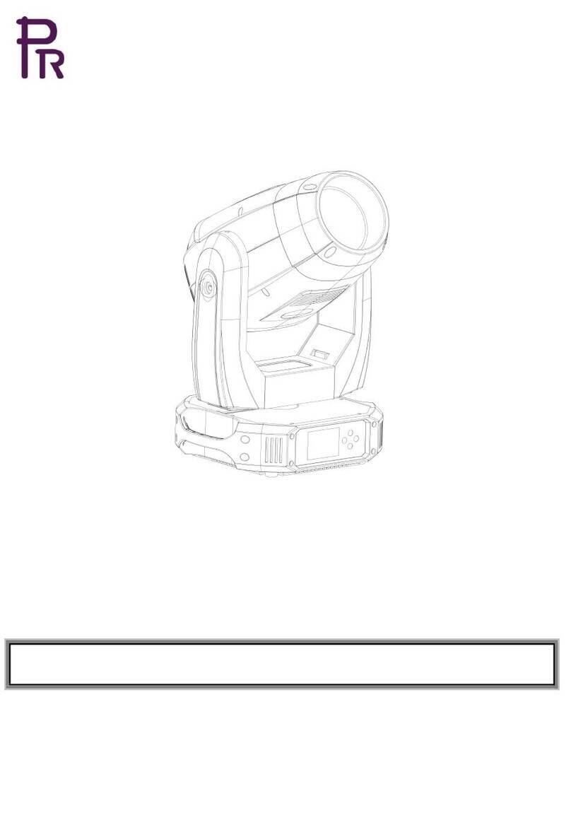
PR XRLED 400 BWS User manual

2
INDEX
1.
SAFETY AND WARNINGS…………………………………………………………………………………
3
2.
INSTRUCTIONS……………………………………………………………………………………………
4
3.
APPERANCE…………………………………………………………………………………………………
5
4.
INSTALLTION…………………………………………………………………………………………………
5
5.
SETUP AND TONFIGURATION……………………………………………………………………………
10
6.
OPERATION MENU…………………………………………………………………………………………
11
7.
DMX PROTOCOL ……………………………………………………………………………………………
13
8.
ERROR MESSAGES………………… ………………………………………………………………………
16
9.
TECHNICAL DATA…………………………………………………………………………………………
16
10.
CIRCUIT DIAGRAM …………………………………………………………………………………………
20
11.
COMPONENT ORDER CODES………………………………………………………………………………
21
APPENDIX……………………………………………………………………………………………………
22
ACCESSORIES
The following items are supplied with the projector and please check:
Name
Quantity
Unit
Remark
Safety cord
1
Pc
Clamp
2
Pc
Foldable clamp
2
Pc
Optional
User manual
1
Pc
Please note that as part of our ongoing commitment to continuous product development, specifications are subject to change
without notice. Whilst every care is taken in the preparation of the manual we reserve the right to change specifications in the
course of product improvement. The publishers cannot be held responsible for the accuracy of the information herein, or any
consequence arising from them.
Every unit is tested completely and packed properly by the manufacturer. Please make sure the packing and / or the unit are in
good condition before installation and use. Should there be any damage caused by transportation, consult your dealer and do not
use the unit. Any damage caused by improper use will not be assumed by the manufacturer and / or dealer
Any future technical change in the user manual won’t be with any notice.
Note: Products are calculated on the date of delivery by the company, the warranty for the whole product is one year starting
from the delivery date but the light source is not within the warranty

3
1. SAFETYAND WARNINGS
NOTE
Before a projector’s installation, power-on, operation and maintenance, please carefully read the
safety information hereinafter!
The following safety signs are used in the user manual.
Warning
User
Manual
Electrical
shock
Goggles
Protective
Gloves
Flames
High
Temperature
●● When unpacking , check if there is transportation damage before using the projector. Should there be
any damage causedby transportation,consultyourdealer and do not use it.
●● The manufacture is not responsible for loss caused by the user not following the manual or changing
the projector as he/shelikes
●● Pleasebe notedthatthedamage causedby changing theprojectorat willis notwarranted.
●● Do nothesitateto contactthe dealeror the manufacturerif any questionsor advice.
●● If a lamp is damagedor deforms becauseof heat, it shouldbe replaced.
● Theprojectoris for indoor use only,IP20.
● It cannot be used in humid and dusty areas. And it cannot contact water and other non-corrosive
liquids.
● The projector should be kept away from high temperature, fire, electrical surge, vibration and
strong light while being operated
● The projector is only intended for installation, operation and maintenance by qualified personnel.
And the operation must strictly follow the procedures in the manual
● No repairable parts in the projector and do not open covers for maintenance by yourself.
● Don’t look straightly into the light sources especially for epileptics, otherwise eyes will be burned.
● Do not connect a projector to any type of dimmer pack.
● If the lamp, lens and screen protective cover of the a projector have obvious damage, i.e., to the
extent that it hurts the performance like cracking or deformation. Please stop using it and replace
them with the original parts, otherwise its performance will be compromised.
● For the installation location of a projector, it shouldn’t be seen in the distance of less than 4 meters
for a long time.
● Before operation, please confirm that all covers (housing) are on and screws tightened. It’s
forbidden to use a projector while covers (housing)are off .
● Keep the lamp clean and do not touch it with bare hands.
● While operating it, wear protective items like eye goggles , gloves and etc.
● Anyelectricalconnectionmustbe carried out by a qualifiedperson .
● Beforeinstallation,pleaseconfirm the voltagesuppliedmatcheswhat is requiredfortheprojector
● Eachprojectormustbe properlyearthedandinstalledas per relatedelectricalstandards.
● Do notusepower cordwith its insulator damagedandconnect the powercordwith other cables.
● If the projector is not used or under cleaning,, please hold the plug and unplug it. Do not unplug it forcefully
or by pullingthe powercable.
● All power cordsmust conform to relatedsafety and regulations
● While beingoperated, the projectorshouldnot be under rains or in humidity.
● Do not switch on and off the projector constantly in very short intervals, otherwise the light source’s and

4
other electrical parts’ life will be shortened
●There are safety cord holes at the bottom of the base of a projector. In view of safety, please run the
safety cord supplied through the safety cord holes for safety support.
●Before any installation, maintenance and cleaning work, please ensure a projector is disconnected
from power mains.
●After stableoperationunder normalsituation, its temperature is 80℃.
●While the lamp is stricken for the first time, there will be smoke and strange smell. It’s normal and
does not mean a projector has some defects.
●While it running, don’t touch the metal housing to avoid being burned!
●Do not mount a projector directly on inflammable surface.
●Do not project the beam straightly on combustible items and the minimum distance between a
projector and illuminated items is 8m.
●A projector should be installed with good ventilation and the minimum distance between a
projector and a wall is 50cm. At the same time, please ensure the fans and air inlets and outlets are
workable.
●Do not let the front lens under sunlight or other strong light sources at any angle, otherwise the
danger of fire can be caused by the focused beam by the lens inside a projector.
● The product meets The General Technical Requirements and Standards for Recycle and Use Of Expired
Appliance and ElectronicProducts
● Whentheproduct meetsdisposalstandardsandneedsto be disposed,a clientneedsto disposeandrecycleit.
2. INSTRUCTIONS
●
CLEANINGAND MAINTENANCE
Keeping a projector is necessary and the dust, oil and smoke should not accumulate on or in it, otherwise its light output will be greatly
compromised. Regular cleaning will ensure light output at maximum and reliable running during its whole life span. It’s advised to use
softcloth with goodqualitydetergent. Under whatevercircumstances, it shouldnot use alcoholor other solvent.
For the accumulation of oil and smoke on the front lens, thus sharp decreasein light output, the front lens should be cleaned once every
week. Cooling fans cleaned once every month. Internal items inside the projector should be cleaned once every year using vacuum or
blower. Colorfilters, rotators and internalmirrorsshould be cleanedonce every month.
Regular inspection of air filters and clean them before they fully blocked. Clean air filters at the bottom of the base. Please vacuum or
compressedair to cleanand put them backafter cleaning.
●Beforeany maintenanceandcleaning,please ensurethe projectis off thepower
●Only qualifiedperson is allowed to do maintenance
●During maintenanceand before maintenance,theprojectormustbe off power.
●To avoid internal damage, sun light or other light mustn’t penetrate into the projector via front lens whether it
runs ornot
●Do notusealcoholor otherorganic solventto clean thehousingto avoiddamage.
●Do notuseany solventwith chemical elementsto clean color filters or hot mirror.
. Hot mirror should be cleaned every 3 days and coated with
●
LUBRICATION
To ensure smooth movement of gobos and zoom and focus lens, it’s advised rotators’ bearings and 2 sliding bars for zoom and focus
lensbe lubricated every 2 months.High qualityand hightemperature lubricant/grease is advised..

5
●
TROUBLESHOOTING
PROBLEM
ACTION
The projector doesn’t switch on
Check thefuseon thepowersocket.
Check thelamp.
The lamp is on butthe projectordoesn’t respond
to thecontroller
Makesure that the fixture’sstart addressis right
Replace or repairtheXLR signalcable.
The projector functions intermittently
Makesurethefanisworkingwellorfansandtheirshieldsarenotblocked
Beam appears dim, Low in brightness
Makesurethelamp is withinitslifespan
Remove dust or greasefrom the lenses.
The project image appears to have a halo
Carefullyclean thelamp,opticallensesandother components.
Heavily Defective Beam
Check if lens are in good condition(not cracked)
Cleandust or grease on the lens.
3. APPEARANCE
4. INSTALLATION
A projector can be placed on the stage floor directly or mounted on a truss at any direction without impacting its performance. Please
use a safety cord, which can support 10 times the weight of the projector, while mounting it on the truss. The safety cord should be
used with magazine with a lock. Just as the figures below, please run the safety cord through the holes at the bottom of the base and
around thetruss.
●
RIGGING
1.
UseM12 bolt to fixthe clamp(1)intothe omega holder (3), run the bolt through the holder’s holes
2.
Push2 quick-lockfasteners(4)into holesat the bottomof thebase, fix themandtightenthem clockwise
3.Runsafety cord(2)through holes at thebottom of the base and around the truss(6)
Head
Arm
Base

6
The bracket of BASE:
Use the spanner supplied with a projector to help installation.
WARNING:
●TheprojectorMUST be lifted or carriedby theHANDLESinstead of clamps.
●.Forsafetythesafety cordshould afford10 times the Projector’s weight.
It must use secondary safety accessory like appropriate net. The structures of the secondary accessory must ensure that while
malfunction happens, the installed parts won’t fall to the ground.
While rigging, mounting or maintaining, the projector mustn’t be placed in the areas listed hereinafter: the bridge, high work
areas or other dangerous areas.

7
The operator of the projector or its related safety items must be accepted by safety experts before first launching or re-running
after any replacementsor repairing.
The operator must ensure a test before acceptance every 4 years and the related safety measures and installation accepted by
experts.
The operator must ensure the related safety measures and its installation must be approved by the technicians every year. The
projector may be installed in places under which people may walk by or sit. Important! Installations in high places requires
wide experience, including but not limited to load limit calculation, the installing materials needed and regular inspection of
installing materials and the projectors. If lacking the qualifications, please don’t try installation by yourself, but seek help from
professionals using designated lifting gears. Abnormal installation may cause body harm or property damages.
The projectors must be installed in places where people can’t reach. If they are removed from ceiling or high places,
professional truss must be used. It is forbidden to let any projector move freely in a room after installation.
Note: Device falling down can cause heavy body harm! If you have any questions about its safety, don’t install any projector!
Before installation, please ensure mounting areas can endure 10 times the weight of a project at least.
●
POWER CONNECTION
Connect the power cord as follows:
L(live) =brown
E (earth)
=yellow/green N
(neutral) =blue
Before power connection, please ensure the power supplied must match what the nameplate says. It is recommended that each
projector be connected with power separately so that they may be individually switched on and off.
●
The earth wire(yellow/green) must be connected to the ground.And electrical
connection must be in accordance with the standards concerned.
●
If any questions about the electrical installation, do not continue but consult a qualified
electrician.
●
DMXCONTROLCONNECTION
Connection between controller and projector and between one projector and another must be made with a twin-screened cable, with
each wire having at least a 0.5mm in diameter. Connection to and from the projector is via cannon 5 pin (which are included with the
projector) or 5 pin XLR plugs and sockets. TheXLR'sare connected as shown in the figureabove.
Note: care should be taken to ensure that none of the pins touch the metallic body of the plug or each other. XLR plugs and sockets
mustn’t be connected in any way other than mentioned in the above figure. The fixture accepts digital control signals in protocol
DMX512 (1990).
Connect the controller’s DMX output to the first fixture’s DMX input, and connect the first fixture’s DMX output to the second
fixture’s DMX input and connectthe rest fixtures in the same way. Eventuallyconnect the last fixture’sDMX output to a DMXterminator
as shown in the figurebelow.

8
●
DMXTERMINATOR
In theController mode,at the last fixturein thechain, the DMX output has to be connectedwith a DMX terminator.Thisprevents
electrical noisefromdisturbingandcorruptingthe DMXcontrol signals.
The DMX terminator is simply an XLR connector with a 120(ohm) resistor connected across pins 2 and 3, which is then plugged into
the output socket on the last projector in the chain. The connections are illustrated below.
21
3
120
DMX TERMINATOR
CONNECTION
Connect a 120 (OHM) resistor
across pins 2 and 3 in an XLR plug
and insert into the DMX out socket
on the last unit in the chain.
PIN 3
PIN 2
GOBO REPLACEMENT
1.
Disconnect the projectorwith mains powerand letit cool
2.
After loosening 4 1/4 fasteners of the head cover,remove it
3.
Gentlypull the gobo holder(3)fromrotating gobo wheel upward.
4.
Use appropriate tool like flat screwdriver of small size to remove spring lock(1). Do not use bare hand to touch pattern side of
the gobo.
5.
Remove the old gobo(2) and insert new one with the smooth side facing light source. At the edge of the Gleelite gobo, there
is small positioning point(8), which must overlap with gobo holder’s positioning point(4). Insert spring lock and fix the gobo
inside the goboholder.
6.
Insert the gobo holder into the rotating gobo wheel via locking pins (6 and 7) and ensure positioning point (4) overlaps
extruding point in the shape of tooth at the edge of the rotating wheel(5). Important! After inserting rotators into the wheel, the
neighboring rotators must be positioned based on same rules, which means positioning point(4) must overlap extruding point(5)
at the edge of the wheel. With 2 markings (4) and (5), when the wheel is at proper position where the rotators can be inserted,
the rotators can be placedone by one.
7.
Beforepoweron,pleaseinstalltheheadcover.
8.
Use menuto fine tune replaced gobos( Service->Calibration->Standard effect->R. Gobo Indexing1…R Gobo Indexing(6)
Note:The magnet(9) in the gobo holderis of thesame function as thepositioningpoint(4).

9
DANGER!
BEOFORE GOBO REPLACEMENT, IT MUST BE OFFPOWER!

10
5. SETUPAND CONFIGURATION
●
FRONTPANELOPERATION
To browse through or view a projector’s function settings, push any key to activate the screen after power-on.. After screen
unlocked, push both key and to enter into menus. Each main menu has its sub-menus with different special functions, for
detailspleasesee the 5th point hereinafterOPERATIONMENU.
1、Under menu page for functionsettings,push ▲or▼to select function desired.
2、During menu operation▶key is to escape,OK key means ENTER,push OK key to save settings or enter into
submenus,push
▲or▼key to change values(plus or minus). Push▶key to go back to uppermenu.If not, the screenwill go
backto initial displayautomatically.
●DMXSTARTADDRESS
Push any key to enter into options interface.
If multipleprojectors are controlled by DMX controller, each projector must have its own DMX address to receive DMX signals from the
controller and respond to them. The projector has 2 DMX modes. There are short mode and standard mode. For example standard mode
has 27 channels, so set the No. 1 projector’s address 001, No. 2 projector’s address 028, No. 3 projector’s address 055, No. 4 projector’s
address82 andso on.
Turn on a projector and push any key to enter into options interface
SelectCHANNELMODE iconandpushENTERkey OK . Select DMXADRESS in 2nd levelmenuto set start address
PushkeyUP ▲or DOWN▼to set value desired.
PushENTERkey OK to confirmit.
Push ESCAPEkey▶to enterintoupper levelmenus.
●STAND-ALONEMODE
Without connecting a projector with a controller via XLR cable, after preset memories under the master mode enabled, it
will run in Stand-Alone mode.
●MASTER/SLAVEMODE
(1)
Edit the scene desired
Twowaysto edit scene
a.
Editmanually
Disconnect a projector from XLR cable and enter into scene editing via control panel.A scene has 20 steps and select any step via its
sequence No.. Enter into channel control to edit its data. After disconnected from a DMX controller, a projector will respond to data
editedsimultaneously.
b.
Editwithhelpof a DMXcontroller
Use a DMX controller to control a projector. After the projector is controlled properly in positions, select the sequence No. of step to
be saved and click to store DMX values.
Current DMX data will be automatically saved to its scene’s data and the sequence NO. added 1. And so on, it can save 20-step scene.
(2)
Select use mode from scene menu.There are 2 modesforselection:singleand recycle. If not used,it can be closed.

11
6. OPERATION MENU
Main Menu
Level 1
Level 2
Level 3
Press the button
DMX Address
code Settings
Address:
001
001-512
Channel Mode:
22CH/28CH
Reset
Motor Power
On/off
Reset All
On/off
Pan Tilt
On/off
Color
On/off
Gobo
On/off
Beam Path
On/off
Run
DMX/User/Auto
Manual
Pan
0-255
Tilt
0-255
P/T Speed
0-255
Strobe
0-255
Dim
0-255
Color
0-255
Gobo
0-255
GoboWheel
0-255
Rot Gobo
0-255
Prisml
0-255
Rot Prisml
0-255
Fire Arm
0-255
Fire Wheel Rot
0-255
Frost
0-255
Zoom
0-255
Focus
0-255
C
0-255
M
0-255
Y
0-255
CTO
0-255
Run Settings
Pan/Tilt Settings
Manual Pan/Tilt
On/off
X Reverse
N/Y
Y Reverse
N/Y
Speeed Chn
Yes/No

12
DimCurve
Linear/Square/Square
Root/S-Curve/Log
If No DMX
Power On
Middle/Auto/User/No Effect
Run Time
Shutter Off/Keep
Silent Mode
OFF/ON
Advanced Settings
Adj
Input PSW
****
LCD Display
Sleep
30sec/2min/10min/No
Flip
No/Yes
Auto Lock
N/Y
Language
English/Chinese
Ignore Err
Raster Waveform
No/Yes
Adj Recover
Input PSW
****
Info
DMX Value
Error
LED
Usage Times
****hr
Clear Times
****
Test Mode
Fan Test
Pan/Tilt

13
7. DMX PROTOCOL
DMX channel
Value
Function
Short Mode
22CH
Standard
28CH
1
1
Pan
0-255
0-100%
2
Pan Fine
0-255
0-100%
2
3
Tilt
0-255
0-100%
4
Tilt Fine
0-255
0-100%
3
5
Pan and Tilt speed
0-255
Fast ->Slow
4
6
Strobe
0-3
Close
4-103
Strobe: Slow->Fast
104-107
Open
108-207
Pulse strobe: Slow->Fast
208-212
Open
213-225
Strobe at random: slow speed
226-238
Strobe at random: medium speed
239-251
Strobe at random: fast speed
252-255
Open
5
7
Dimmer
0-255
0-100%
8
Dimmer Fine
0-255
0-100%
6
9
C
0-255
0-100%
7
10
M
0-255
0-100%
8
11
Y
0-255
0-100%
9
12
CTO
0-255
0-100%
10
13
CMY macro
0-3
No function
4-255
CMY to-and-fro movement
11
14
Colors
0-7
Open
8-15
Open+Color1
16-23
Color1
24-31
Color1+Color2
32-39
Color2
40-47
Color2+Color3
48-55
Color3
56-63
Color3+Color4
64-71
Color4

14
72-79
Color4+Color5
80-87
Color5
88-95
Color5+Color6
96-103
Color6
104-111
Color6+Color7
112-119
Color7
120-127
Color7+Open
128-190
Clockwise rotation: Fast->Slow
191-192
Stop
193-255
Anti-clockwise rotation: slow->fast
12
15
Fixed gobo wheel
0-5
Open
6-15
GOBO1
16-25
GOBO2
26-35
GOBO3
36-45
GOBO4
46-55
GOBO5
56-65
GOBO6
66-75
GOBO7
76-92
GOBO1 SHAKE: Slow->Fast
93-109
GOBO2 SHAKE: Slow->Fast
110-126
GOBO3 SHAKE: Slow->Fast
127-143
GOBO4 SHAKE: Slow->Fast
144-160
GOBO5 SHAKE: Slow->Fast
161-177
GOBO6 SHAKE: Slow->Fast
178-199
GOBO7 SHAKE: Slow->Fast
200-201
Open
202-227
Clockwise rotation: Fast->Slow
228-229
Stop
230-255
Anti-clockwise rotation: slow->fast
13
16
Rotating GOBO wheel
0-5
Open
6-15
GOBO1
16-25
GOBO2
26-35
GOBO3
36-45
GOBO4
46-55
GOBO5
56-65
GOBO6
66-75
GOBO7
76-92
GOBO1 SHAKE: Slow->Fast
93-109
GOBO2 SHAKE: Slow->Fast
110-126
GOBO3 SHAKE: Slow->Fast
127-143
GOBO4 SHAKE: Slow->Fast
144-160
GOBO5 SHAKE: Slow->Fast
161-177
GOBO6 SHAKE: Slow->Fast
178-199
GOBO7 SHAKE: Slow->Fast
200-201
Open
202-227
Clockwise rotation: Fast->Slow
228-229
Stop

15
230-255
Anti-clockwise rotation: slow->fast
14
17
GOBO Rotation
0-127
Positioning:0-360°
128-191
Clockwise rotation: Fast->Slow
192-255
Anti-clockwise rotation: slow->fast
18
GOBO Rotation fine
0-255
0-100%
15
19
4 facet prism
0-127
No Function
128-255
Prism in
16
20
4 facet prism rotation
0-127
0-360°
128-190
Clockwise rotation: Fast->Slow
191-192
Stop
192-255
Anti-clockwise rotation: slow->fast
17
21
Effect wheel
0-127
No Function
128-255
Effect wheel in
18
22
Effect wheel rotation
0-3
No Function
4-129
Clockwise rotation: Fast->Slow
130-255
Anti-clockwise rotation: slow->fast
19
23
Frost
0-255
0-100%
20
24
Zoom
0-255
0-100%
25
Zoom Fine
0-255
0-100%
21
26
Focus
0-255
0-100%
27
Focus Fine
0-255
0-100%
22
28
Functional channel
0-199
No Function
200-209
Pan & Tilt reset
210-219
Head reset
220-229
All reset
230-255
No Function

16
8.ERROR MESSAGE
Name
Type
Correction
Pan
Optical sensor error: Pan
Check if wiring, optical sensor and motors are normal
Tilt
Optical sensor error: Tilt
Check if wiring, optical sensor and motors are normal
Pan & Tilt driver board
Communication error: module1
Check if wiring, hall sensor and motors are normal
Motor driver board
Communication error: module2
Check if wiring, hall sensor and motors are normal
Focus
Hall error: Focus
Check if wiring, hall sensor and motors are normal
Zoom
Hall error: Zoom
Check if wiring, hall sensor and motors are normal
Effect wheel
Hall error: Effect wheel
Check if wiring, hall sensor and motors are normal
Color wheel
Hall error: Color wheel
Check if wiring, hall sensor and motors are normal
Fixed gobo wheel
Hall error: Fixed gobo wheel
Check if wiring, hall sensor and motors are normal
Rotating gobo wheel
Hall error: Rotating gobo wheel
Check if wiring, hall sensor and motors are normal
GOBO Rotation
Hall error:GOBO Rotation
Check if wiring, hall sensor and motors are normal
9. TECHNICALDATA
ELECTRIC PARAMETERS
Input voltage : 120V~240VAC,50/60Hz
Input power : 600W @ 220V
Current at Maximum : 4.5A @ 120V
Power factor: PF>0.9
THE SPECIFICATIONS OF THE LIGHT SOURCE
LED : 500W White LED Engine
Colortemperature :7800K±200K
CRI : >72 (Standard)
CRI : >90 (Optional)
LED life expectancy: 40000Hrs L70
*It may change based on various factors, for example like the type of usage and environment condition*
COLORS
1Color wheel: 7colors + Open
CMY+CTO

17
CMY
C M
Y CTO
FIXED GOBO WHEEL/EFFECTWHEEL
1 fixedgobowheel:7gobos+open, gobodiameter=6.5mm,itsthickness=0.5mm
1
2
3
4
5
6
7
1 fireeffectwheel
ROTATING GOBO WHEEL
1 rotating gobo wheel: 7 gobos +open Gobo diameter Ф19.5mm, 4mm thick
1
2
3
4
5
6
7

18
PRISM/FROST
1 4-facet prism
1 Frost
FOCUS
DMX linear focus
DIMMER /STROBE
Strobe at variable speeds
0-100% linear dimmer
HEAD MOVEMENT
Pan 540º, Tilt 270º with 16 bit control
BEAMANGLE
Beam: 5°~45°
Spot :11°~46°
Wash: 8°~ 48°
CONTROL
Projectorand lamp information readable,externalDMX value receivedand thermal sensor built-in forerrorandmalfunction
analysis Presetmemory
Unintentional head move to cause power-off, quiet fans for cooling
International standard DMX 512 protocol, 5-pin interface 22channelsin short mode and 28channels in standard mode
OPTIONALWIRELESS CONTROLMODULE/RDM MODULE
Compliantwith USITTDMX-512(1986and 1990)and512-AFullDMX for fidelity and DMX framingintegrity
Auto-detecting DMX framing size and speed
<5ms DMX delay
Frequency range: 2402-2480 MHz
HOUSING
High temperature ABS and aluminum , IP20
OPERATION TEMPERATURE
Ambient temperature at maximum:45°C
Ambient temperature at minimum:-5°C
NET WEIGHT:
21.5Kg
SIZES:

19
LIGHT OUTPUT

20
10. CIRCUIT DIAGRAM
This manual suits for next models
1
Table of contents
Other PR Light Fixture manuals
Popular Light Fixture manuals by other brands

dtec
dtec Denta/Dentaplus owner's manual

Sensio
Sensio TRIOTONE SE21100 installation instructions
Fisher
Fisher Mini Strobe Light quick start guide

Martin Professional
Martin Professional Wizard Extreme user manual
Tungsram
Tungsram HighBay G2 Install Instruction Guide

Coemar
Coemar ISPOT 575 EB instruction manual

