PR AQUA Laser 260 BWS User manual


2
INDEX
1.
SAFETYAND WARNINGS……………………………………………………………………………………
3
2.
INSTRUCTIONS…………………………………………………………………………………………………
4
3.
APPEARANCE …………………………………………………………………………………………………
5
4.
INSTALLATION…………………………………………………………………………………………………
5
5.
SETUPAND CONFIGURATION…………………………………………………………………………………
9
6.
OPERATION MENU……………………………………………………………………………………………
10
7.
DMX PROTOCOL………………………………………………………………………………………………
15
8.
ERROR MESSAGE……………………………………………………………………………………………
19
9.
SIGNS ON THE TOUCH SCREEN ……………………………………………………………………………
20
10.
TECHNICAL DATA……………………………………………………………………………………………
20
11.
CIRCUIT DIAGRAM……………………………………………………………………………………………
24
12.
COMPONENT ORDER CODES…………………………………………………………………………………
25
ACCESSORIES
The following items are supplied with the projector and please check:
Name
Quantity
Unit
Remark
G clamps
2
Pcs
XLR connectors
1
Set
Male and female
Safety cord
1
Pc
User manual
0
Pc
QR Code
Ω clamps
2
Pcs
Optional
Please note that as part of our ongoing commitment to continuous product development, specifications are
subject to change without notice. Whilst every care is taken in the preparation of the manual we reserve the
right to change specifications in the course of product improvement. The publishers cannot be held responsible
for the accuracy of the information herein, or any consequence arising from them.
Every unit is tested completely and packed properly by the manufacturer. Please make sure the packing and /
or the unit are in good condition before installation and use. Should there be any damage caused by
transportation, consult your dealer and do not use the unit. Any damage caused by improper use will not be
assumed by the manufacturer and / or dealer.
Note: For the products made by Guangzhou PR lighting Ltd, the warranty for the whole product is one year starting from
the delivery date but the light source is not within the warranty.
3
1. SAFETYAND WARNINGS
NOTE
Before a projector’s installation, power-on, operation and maintenance, please carefully read
the safety information hereinafter!
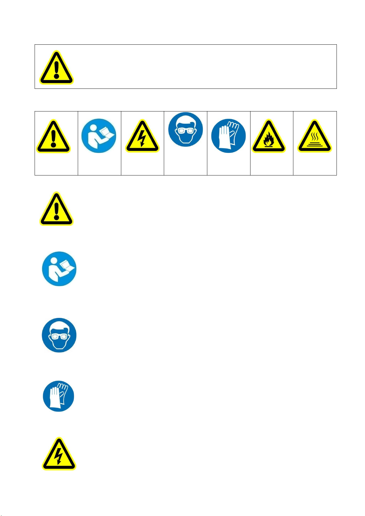
The following safety signs are used in the user manual.
Warning
User
Manual
Electrical
shock
Goggles
Protective
Gloves
Flames
High
Temperature
● When unpacking, check if there is transportation damage before using a projector. Should there be any damage
caused by transportation, consult your dealer and do not use it.
●The manufacturer is not responsible for any loss caused by the user not following the manual or changing a
projector as he/she likes.
●Please be noted that the damage caused by changing a projector at will is not warranted.
● Do not hesitate to contact the dealer or the manufacturer if any questions or advice.
●If a lamp is damaged or deforms because of heat, it should be replaced.( It applies only to traditional lamps)
● The projector is for indoor and outdoor use, IP66.
● It can be used in humid and dusty areas.And it can contact water and other non-corrosive liquids.
● The projector should be kept away from high temperature, fire, electrical surge, vibration and strong light while
being operated
● The projector is only intended for installation, operation and maintenance by qualified personnel. And the
operation must strictly follow the procedures in the manual
● No repairable parts in the projector and do not open covers for maintenance by yourself.
.
●Don’t look straightly into the light sources especially for epileptics, otherwise eyes will be burned.
●Do not connect a projector to any type of dimmer pack.
●If the lamp, lens and screen protective cover of the a projector have obvious damage, i.e., to the extent that it
hurts the performance like cracking or deformation. Please stop using it and replace them with the original parts,
otherwise its performance will be compromised.
● For the installation location of a projector, it shouldn’t be seen in the distance of less than 4 meters for a long
time.
●Before operation, please confirm that all covers (housing) are on and screws tightened. It’s forbidden to use a
projector while covers (housing)are off .
●Keep the lamp clean and do not touch it with bare hands.
●While operating it, wear protective items like eye goggles , gloves and etc..
●Any electrical connection must be carried out by a qualified person .
●Before installation, please confirm the voltage supplied matches what is required for a projector.
●Each projector must be properly earthed and installed as per related electrical standards.
●Do not use power cord with its insulator damaged and connect the power cord with other cables.
●If a projector is not used or under cleaning,, please hold the plug and unplug it. Do not unplug it forcefully or by
pulling the power cable.
4
●All power cords must conform to related safety and regulations.
●If a projector is not water and dust proof, while being operated it should not be under rains or in humidity to
avoid short circuit.
●Do not switch on and off a projector constantly in very short intervals, otherwise the light source’s and other
electrical parts’life will be shortened .
●There are safety cord holes at the bottom of the base of a projector. In view of safety, please run the safety cord
supplied through the safety cord holes for safety support.
●Before any installation, maintenance and cleaning work, please ensure a projector is disconnected from power
mains.
● While running normally under normal ambient temperature, the temperature of the external surface of the
metal housing of a projector including that of the heat sink may reach 75℃ at maximum.
●While the lamp is stricken for the first time, there will be smoke and strange smell. It’s normal and does not
mean a projector has some defects.
●While it running, don’t touch the metal housing to avoid being burned!
●Do not mount a projector directly on inflammable surface.
●Do not project the beam straightly on combustible items and the minimum distance between a projector
and illuminated items is 18m.
●A projector should be installed with good ventilation and the minimum distance between a projector and a wall
is 50cm.At the same time, please ensure the fans and air inlets and outlets are workable.
●Do not let the front lens under sunlight or other strong light sources at any angle, otherwise the danger of fire
can be caused by the focused beam by the lens inside a projector.
● The product meets The General Technical Requirements and Standards for Recycle and Use Of Expired
Appliance and Electronic Products.
● When the product meets disposal standards and needs to be disposed, a client needs to dispose and recycle it.
2. INSTRUCTIONS
●CLEANINGAND MAINTENANCE
Under normal running, the protective units of a projector should be inspected regularly like power fuse. If it is burned, please
install a new one and ensure it is the same rating as the burned one. For a projector with an over-temperature protective unit,
please inspect cooling units regularly like cooling fans, heat sink and other cooling parts. Please check if the fans run normally or
fans and air inlets are blocked by dust. To keep air inlets /outlets clean, cooling fans should be cleaned every 15days.
For projectors with lens, reflectors and coated filters, the accumulation of oil, smoke and dust on them will compromise the light
output. Cleaning a projector is very necessary to ensure a reliable use. Internal and external lens, flat glass, reflector and coated
filters need to be cleaned periodically to optimize light output.
Cleaning frequency is to be decided by operations and its environment. Use soft cloth and normal detergent for glass for cleaning
work. It’s advised external optical system be cleaned every 20days and internal optical systems every 30/60days. For a projector
with high IP rating, if no damage inside, it is advised to clean the surfaces of its housing in principle. Keep lens clean and do not
touch optical parts with bare hands.
SPECIAL NOTE:
It’s normal phenomena that there will be mild water mist on the lens while the waterproof product is in use.
●Before any maintenance and cleaning, please ensure a project is off the power.
●Only a qualified person is allowed to do maintenance.
5
●To avoid sunlight or other light penetrating into the head via the front lens, resulting in high temperature
internally causing damages to a projector. Before power-off, please use Tilt channel to move the head and
make the head facing downward.
● Do not use alcohol or other organic solvent to clean the housing to avoid damage.
● Do not use any solvent with chemical elements to clean coated filters.
●LUBRICATION
To ensure smooth movement of gobos and zoom and focus lens, it’s advised rotators’ bearings and 2 sliding bars for zoom and
focus lens be lubricated every 2 months. High quality and high temperature lubricant/grease is advised..
●TROUBLESHOOTING
PROBLEM
ACTION
A projector doesn’t switch on
Check the fuse on the power socket.
Check the lamp.
The lamp is on but a projector doesn’t respond to
the controller
Make sure that the fixture’s start address is right
Replace or repair the XLR signal cable.
A projector functions intermittently
Make sure the fan is working well or fans and their shields are not blocked
Beam appears dim, Low in brightness
Make sure the lamp is within its lifespan
Remove dust or grease from the lenses.
The project image appears to have a halo
Carefully clean the lamp, optical lenses and other components.
Heavily Defective Beam
Check if lens are in good condition(not cracked)
Clean dust or grease on the lens.
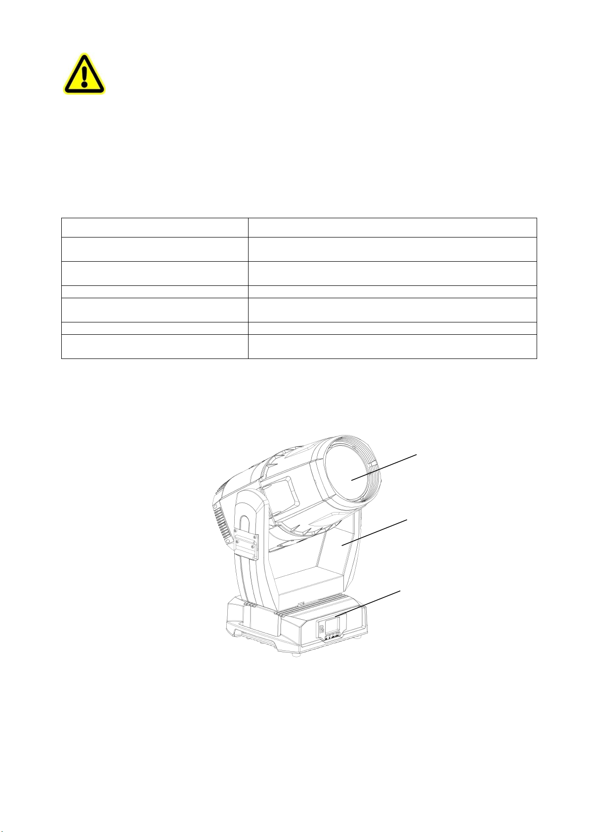
3. APPEARANCE
4. INSTALLATION
●RIGGING
Before moving a projector, Please lock Pan and Tilt. Before its operation, please unlock them. It’s forbidden to run a
projector with power while it is locked.
Head
Arm
Base
6
Take 2 clamps and the safety cord out from the package and mount 2 clamps on the underside of fixture with 2 retainers attached
to each clamp. Hang the fixture on the structure and fasten the screws attached to each clamp. (See the WARNING on the
underside of the base as shown above) To pass the SAFETY CORD through the HOLES for safety! Always ensure that the
projector is firmly anchored to avoid vibration and slipping whilst functioning.Always ensure that the structure that you are going
to mount the projector to is secure and strong enough to support the weight of a XR 1000 Framing.
WARNING:
●The projector MUST be lifted or carried by the HANDLES instead of clamps.
●.For safety the safety cord should afford 10 times the Projector’s weight.
●POWER CONNECTION
Connect the power cord as follows:
L (live) =brown
E (earth) =yellow/green
N (neutral) =blue
Before power connection, please ensure the power supplied must match what the nameplate says. It is recommended that each
projector be connected with power separately so that they may be individually switched on and off.
●The earth wire(yellow/green) must be connected to the ground. And electrical connection must be in
accordance with the standards concerned.
●If any questions about the electrical installation, do not continue but consult a qualified electrician.
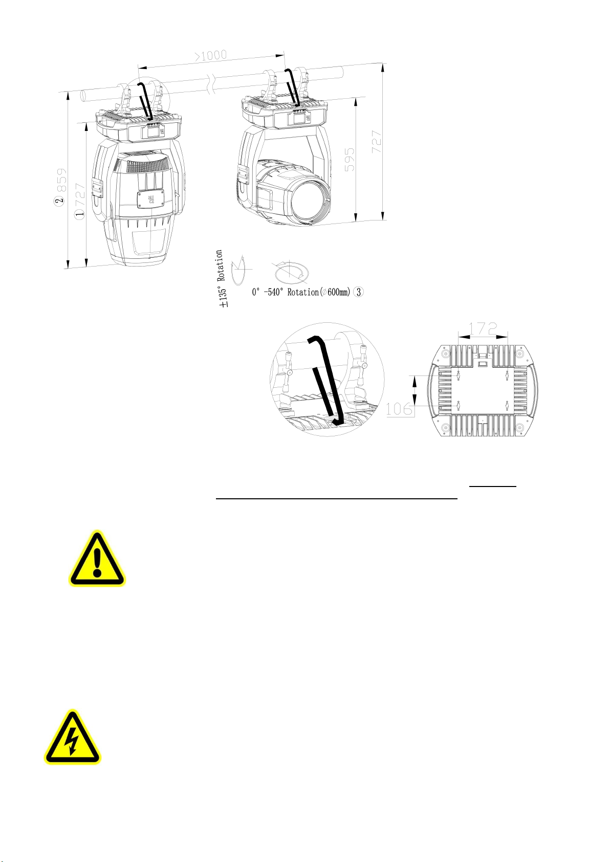
Warning!
For safety, please run the safety cord
through its hole.
Note:
1. the distance between the foot of
the base and the front lens cover(the
head facing downward)
2. the distance between mounting
truss and the front lens cover( the
head facing downward)
3. The maximum diameter of the
rotating head ( minimum spacing
between fixtures)

7
●DMX CONTROLCONNECTION:
Connection between controller and projector and between one projector and another must be made with a twin-screened cable, with
each wire having at least a 0.5mm in diameter. Connection to and from the projector is via cannon 5 pin (which are included with the
projector) or 5 pin XLR plugs and sockets. The XLR's are connected as shown in the figure above.
Note: care should be taken to ensure that none of the pins touch the metallic body of the plug or each other. XLR plugs and sockets
mustn’t be connected in any way other than mentioned in the above figure. The Fixture accepts digital control signals in protocol
DMX512 (1990).
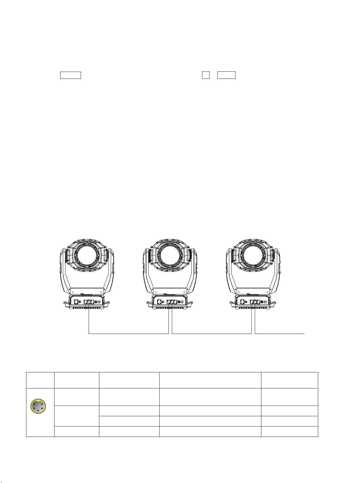
Connect the controller’s DMX output to the first fixture’s DMX input, and connect the first fixture’s DMX output to the second
fixture’s DMX input and connect the rest fixtures in the same way. Eventually connect the last fixture’s DMX output to a DMX
terminator as shown in the figure below.
DMX Teminator
DMX
Controller
Input Output Input Output Input
●DMX TERMINATOR
In the Controller mode, at the last fixture in the chain, the DMX output has to be connected with a DMX terminator. This prevents
electrical noise from disturbing and corrupting the DMX control signals.
The DMX terminator is simply an XLR connector with a 120(ohm) resistor connected across pins 2 and 3, which is then plugged
into the output socket on the last projector in the chain. The connections are illustrated below.
21
3
120
DMX TERMINATOR
CONNECTION
Connect a 120 (OHM) resistor
across pins 2 and 3 in an XLR plug
and insert into the DMX out socket
on the last unit in the chain.
PIN 3
PIN 2
●ALIGNMENT/INSTALLATION/REPLACEMENT OFA LAMP
Please hold the head well before adjustment/installation/replacement of the light sources. As shown in figure1, remove fan cover of
the head and heat sink.
Removal/Installation of the light source as shown in figure2
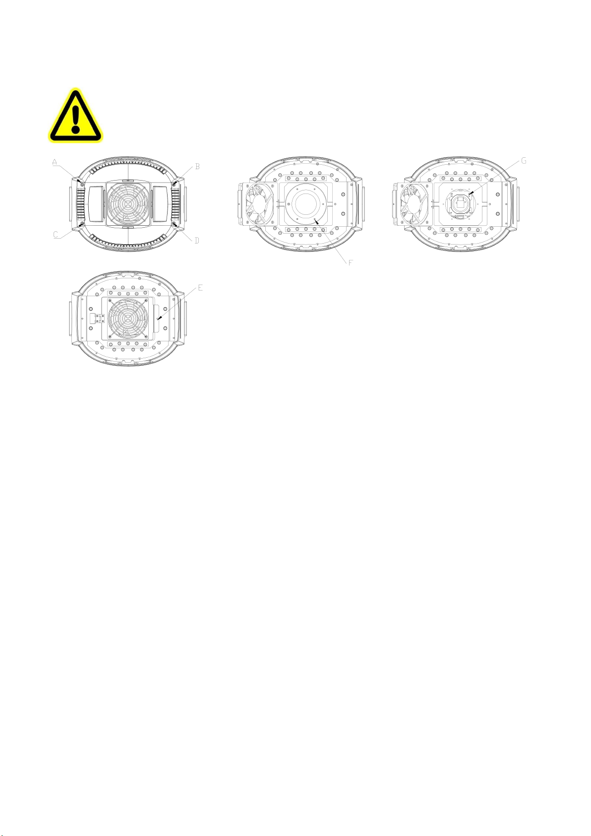
8
Adjust the light source as shown in figure3
Before the removal of the light source, unplug the light source wires.And plug light source wires after a new one is in.
●Don’t touch the surface of the lens of the lamp with bare hands so as not to impair the beam output.
●Please read "Instructions " enclosed with the light source
●While adjusting the light, it is forbidden to carry out the functions not associated with lamp adjustment.
The steps for replacement/adjustment of the light source :
Figure1:Loosen A,B,C,D 4 screws of the bottom cover of the head before removing it. Then loosen the screw E of fan
mounting plate and pull open the fan assembly, exposing the light source chamber cover.
Figure2: Loosen 6 screws F for the light source chamber cover , remove it and take care not to let seal fall off.
Figure3:Loosen 4 screws of the light source clipping plates and push the light source towards the clipping plate till it can be
removed .Take out the light source and unplug its wires. Place a new light source, plug its wires, put back the light souce
chamber cover, tighten the screws and ensure the seal in the right place.At last restore all structures original positions.
1. After the projector is powered on, disable the following function in the menu: services-factory mode- light source fan sensor ,
then shut it from power
2. Loosen the 4 screws of the fan cover and remove it.
3. Loosen 4 screws of the fan plate, remove the fan and the clump weight, loosen 10 screws of the heat sink and remove it.
4. Push the upperclipping plate of the light source towards the spring, and at the same time pus the light source towards the
opposite till it is off the plate and remove it obliquely,
5. The installation of the light source is the same as its removal
6. Check if the light source wires are plugged well, then turn on the light source for adjustment
7. After the adjustment of the light source, activate the following function in the menu: services-factory mode- light source fan
sensor. Then shut it from the power
8. Check if the seals are good ornot. If not, replace them with good ones. If no, install the heat sink, fan and fan cover in the
opposite sequences as the removal.
9. After installation, power it on. The projector will execute the total reset. After that, the projector can be used normally.
●GOBO REPLACEMENT

9
Rotating gobo wheel
Rotator
Gobo
Gobo spring
Rotator
Replacement of the Gobos:
Open the chamber cover after loosening 4 screws.
Select the rotator for replacement of gobo. Push
the rotator at the opposite side of its gear till it is
off the holder of the rotating gobo wheel. Remove
the rotator gently . After replacement of the gobo,
place the rotator into the wheel and ensure it is in
the right position and not loose.
5. SETUPAND CONFIGURATION
●FRONT PANELOPERATION
To browse through or change the projector ’s settings, press ENTER key for more than 3s(press ENTER key after power on) to
unlock the screen , then press UP/DOWN key to enter the projector ’s function menus. Each main menu has its sub-menus. And
each menu stands for special function. For the details, please see the following 6th point ”Operation Menu”.:
1. Atthe page to set the fixture’s functions, press UP or DOWN key to select the functions desired.
2. While menu operations, the FUNC key to escape, and ENTER key is used to confirm. Press ENTER key to save the changes
or enter into the sub menus. Press UP or DOWN key to change the numbers(minus or plus).
Press FUNC key to go to the uppler menu. If no key is pushed, the system will go back to initial status automatically.
●DMX STARTADDRESS
Each projector must be given a DMX start address so that the correct projector responds to the correct control signals. This DMX start
address is the channel number from which the projector starts to “listen” to the digital control information being sent out from the
controller. The projector has 3 DMX modes. There are standard mode ,short mode and extended mode. For example standard mode
has 28 channels, so set the No. 1 projector’s address 001, No. 2 projector’s address 029, No. 3 projector’s address 057, No. 4
projector’s address 085, and so on.
Switch on the Projector . Press ENTER key more than 3 seconds to unlock panel, then press UP or DOWN key to enter into the
fixture’s operation menus.
Select DMXAddress icon and press ENTER key on the display and select DMX address at the 2nd level menu for the address setting.
Press UP or DOWN key for the DMX address desired.
Press ENTER key to confirm.
Press the FUNC key to go back to the upper level menu.
10
.
●DMX WIRELESS CONTROL(Only for fixtures with wireless control)
The projector has wireless control function with wireless receiver module and antenna for remote control.
The setup of it is below:
1. Press ENTER for more than 3s to unlock the control panel, then press UP or DOWN key to enter into the operation
menu and select “Config Settings”.
2. Select “Wireless Only” from the menu of “Signal Select”.
Only after the projector is linked with a transmitter, can it receive wireless signal sent by the transmitter. If unlinking it,
Press “Enter” for the menu of Un-link Wireless under the upper level menu of Config Settigns , then the fixture is unlinked
with the wireless transmitter.
●STAND-ALONE MODE
Operate the projector without connecting with a controller, enable the master mode through the operation panel, the
projector will run in Stand-Alone mode automatically.
DMX address can be set at any number within 512.
●MASTER/SLAVE MODE
Many projectors can run synchronously in the Master/Slave mode by linking them with each other. First,
connect the first fixture’s DMX output to the second fixture’s DMX input using XLR-XLR control cable and then connect the second
fixture’s DMX output to the third fixture’s DMX input, and so on until all projector are connected in this way. Eventually connect the
last fixture’s DMX output to a DMX terminator. Set 1st projector as the master and others are Slaves.
StartAddresses of all Slaves are 001; Operation mode of the Master can be set any mode for a Master’and Slaves’operation mode can
be set accordingly.
After Powered on, the group will run in Master/Slave Mode
Input Output
Master Slave Slave
Input Output Input
DMX
Controller
DMX Teminator
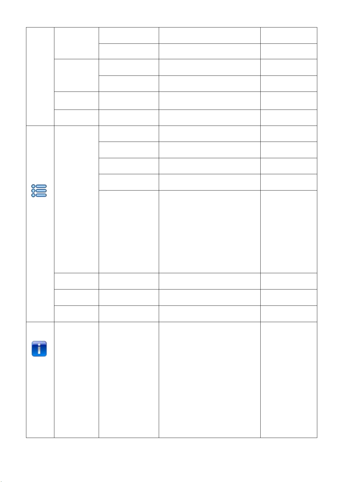
6. OPERATION MENU
1st
LEVEL
2nd LEVEL
3rd LEVEL
4th LEVEL
5th LEVEL
Address
DMX Address
1-490(Short Mode)
1-485(Standard Mode)
1-482(Extend Mode)
IP Address
Default IPAddress
2.X.X.X /10.X.X.X
Custom IPAddress
X.X.X.X
SubNet Mask
X.X.X.X

11
ArtNet
ArtNet Universe
0-255
sACN universe
1-63999
Reset
Total Reset
Really Reset?
Confirm or Cancel
Pan&Tilt Reset
Really Reset?
Confirm or Cancel
Colour System
Reset
Really Reset?
Confirm or Cancel
Gobo Reset
Really Reset?
Confirm or Cancel
Zo. Fo.Fr. Pr. Reset
Really Reset?
Confirm or Cancel
Config
Settings
DMX Channel
Mode
Short Mode 23CH
Standard Mode 28CH
Extended Mode 31CH
View Selected Mode
Ch.01 Strobe
Ch.02 Dimmer
…
Ch. XX control function
Signal Select
XLR Only
XLR First
Wireless Only
Wireless First
Wireless In/XLR Out
Artnet Only
Artnet In/XLR Out
sACN only
sACN/XLR
Loss of DMX
Normal time out
Hold Last Value
Display Config
Display Mode
OffAfter Delay
OnAlways
Display Invert
Invert OFF
Invert ON
12
InvertAuto
Language Setting
English\Chinese
Temperature Unit
Celsius Degree
Fahrenheit Degree
Un-LinkWireless
Really Un-Link?
Confirm or Cancel
Factory Defaults
Restore Defaults?
Confirm or Cancel
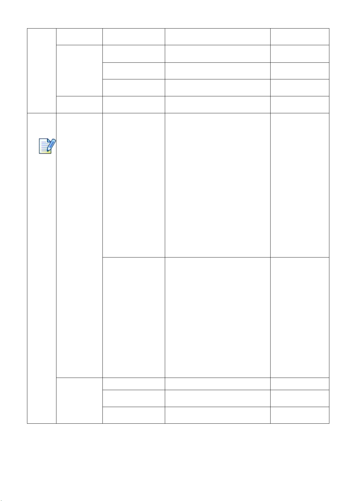
Option
Settings
Pan/Tilt Settings
Pan DMX Invert
OFF/ ON
Tilt DMX Invert
OFF/ ON
PanTilt Swap
OFF/ ON
XYFeedback
OFF/ ON
Pan/Tilt mode
Speed/Time
Note: "Speed Mode"
means Pan and Tilt will
move from Point A to
Point B at their respective
maximum speeds."Time
Mode" means both Pan
and Tilt will arrive at
designated point at the
same time. It's advised
Time Mode be used if the
projector runs circles or in
oblique lines.
Invert Settings
CYM Invert
OFF/ ON
Dimmer Settings
Dimmer Speed
Fast/Medium/Slow Speed
Defaults
Information
View DMX Values
Channel Value
Strobe XXX
Dimmer XXX
CMY macro XXX
Cyan XXX
Yellow XXX
Magenta XXX
Color Wheel XXX
FixedGoboWheelXXX
Rota. Gobo wheel XXX
Gobo Rota. XXX
Prism 1 XXX
Prism 1 Rotation XXX
Prism 2 XXX
Prism 2 Rotation XXX
Frost XXX
Focus XXX
Zoom XXX
Pan XXX
Tilt XXX

13
Control Function XXX
Lamp hours
XXX h
Total hours
XXXh
Temperature
Display Board=×××C
Panboard=×××C
Tilt board=×××C
Motor driver board 1 =×××C
Motor driver board2 =×××C
Light source driver board =×××C
Lightsource==×××C
SoftwareVersion
PCB Sys. bootloader
Display Board xxx xxx
Panboard xxx xxx
Tilt board xxx xxx
Motordriverboard1 xxx xxx
Motordriverboard2 xxx xxx
Lightsourcedriverboard x xx xx
Electronic SN
XXXXXX
RDM Device Label
AQUA Laser 260 BWS
ANSI E1.20 RDM
Fan Status
Fan Speed RSpeed
Base fan xxx on/off
Lens fan xxx on/off
Lightsourcefan xxx on/off
Lamp Fan Error
Fan DMX channel
Base fan xxx
Lens fan xxx
Lightsource fan xxx
Service
Manual Effect
Control
Channel Value
Strobe XXX
Dimmer XXX
CMY macro XXX
Cyan XXX
Yellow XXX
Magenta XXX
Color Wheel XXX
FixedGoboWheelXXX
Rota. Gobo wheel XXX
Gobo Rota. XXX
Prism 1 XXX
Prism 1 Rotation XXX
Prism 2 XXX
Prism 2 Rotation XXX
Frost XXX
Focus XXX
Zoom XXX
Pan XXX
Tilt XXX
Factory Mode
XXX
Operation
Mode
DMX Mode
Change Operation Mode?
Confirm or Cancel
Master Mode
Preset Memory
Change Operation Mode?
Confirm or Cancel
User Memory 1
Change Operation Mode?
Confirm or Cancel
14
User Memory 2
Change Operation Mode?
Confirm or Cancel
Stand-Alone Mode
Preset Memory
Change Operation Mode?
Confirm or Cancel
User Memory 1
Change Operation Mode?
Confirm or Cancel
User Memory 2
Change Operation Mode?
Confirm or Cancel
Static Scene
Change Operation Mode?
Confirm or Cancel
User
Memories
Edit User Memory
Edit User Memory 1
/
Edit User Memory 2
(1~200 Scenes)
Scene XX
(1~200 Scenes)
Channel Value
Strobe XXX
Dimmer XXX
CMY macro XXX
Cyan XXX
Yellow XXX
Magenta XXX
Color Wheel XXX
FixedGoboWheelXXX
Rota. Gobo wheel XXX
Gobo Rota. XXX
Prism 1 XXX
Prism 1 Rotation XXX
Prism 2 XXX
Prism 2 Rotation XXX
Frost XXX
Focus XXX
Zoom XXX
Pan XXX
Tilt XXX
Hold time XXX
Delay Time XXX
Delay time unit ms/s/m
Link to next scene XXX
Edit Static Scene
Paste?
Confirm or Cancel
Channel Value
Strobe XXX
Dimmer XXX
CMY macro XXX
Cyan XXX
Yellow XXX
Magenta XXX
Color Wheel XXX
FixedGoboWheelXXX
Rota. Gobo wheel XXX
Gobo Rota. XXX
Prism 1 XXX
Prism 1 Rotation XXX
Prism 2 XXX
Prism 2 Rotation XXX
Frost XXX
Focus XXX
Zoom XXX
Pan XXX
Tilt XXX
Init User Memory
Reset User Memory 1
Reset User Memory?
Confirm or Cancel
Reset User Memory 2
Reset User Memory?
Confirm or Cancel
Reset Static Scene
Reset Static Scene?
Confirm or Cancel
15
7. DMX PROTOCOL
Short
mode
Standard
Mode
Extended
Mode
FUNCTION
DMX
DESCRIPTION
1
1
1
Strobe
000
Close
001-127
Pulse strobe speed from slow to fast
128-255
Strobe speed from slow to fast
2
2
2
Dimmer
000-255
Linear dimming(0-100%)
3
3
Dimmer Fine
000-255
Dimmer in 16 bit
3
4
4
CYM Macro
000-016
Open
017-035
Yellow+ Magenta=Red
036-054
Yellow
055-073
Yellow +Cyan=Green
074-092
Cyan
093-111
Cyan + Magenta= purple
112-128
Magenta
129-255
CYM color mixing from slow to fast
4
5
5
Cyan
000-255
Cyan (linear 0~100%)
6
Cyan Fine
000-255
Cyan in 16 Bit
5
6
7
Yellow
000-255
Yellow (linear 0~100%)
8
Yellow Fine
000-255
Yellow in 16 Bit
6
7
9
Magenta
000-255
Magenta (linear 0~100%)
10
Magenta Fine
000-255
Magenta in 16 Bit
7
8
11
Color Wheel
000-063
Indexing(0-360degrees)
064-067
Open
068-070
Color1
071-073
Color2
074-076
Color3
077-079
Color4
080-082
Color5
083-085
Color6
086-088
Color7
089-091
Color8
092-094
Color9
095-097
Color10
098-100
Color11
101-103
Color12
104-106
Color13
107-109
Color14
110-112
Color15
113-115
Color16
116-118
Color17
119-121
Color18
122-124
Color19
125-127
Open

16
128-191
Rotation ,Clockwise from slow to fast
192-255
Rotation,Anti-clockwise from fastto slow
9
12
Color Wheel Fine
0000-255
Color Wheel in 16 Bit
8
10
13
Fixed Gobo
Wheel
000-011
Open
012-015
Gobo1
016-019
Gobo2
020-023
Gobo3
024-027
Gobo4
028-031
Gobo5
032-035
Gobo6
036-039
Gobo7
040-043
Gobo8
044-047
Gobo9
048-051
Gobo10
052-055
Gobo11
056-059
Gobo12
060-063
Gobo13
064-067
Gobo14
068-071
Gobo15
072-075
Gobo16
076-079
Gobo17
080-083
Gobo18
084-087
Gobo19
088-091
Gobo20
092-095
Gobo21
096-099
Gobo22
100-103
Gobo23
104-107
Gobo24
108-111
Gobo25
112-115
Gobo26
116-119
Gobo27
120-123
Gobo28
124-127
Gobo29
128-149
Clockwise rotation from slow to fast
150-171
Anti Clockwise rotation from slow to fast
172-174
Shake effect 1 from slow to fast
175-177
Shake effect 2 from slow to fast
178-180
Shake effect 3 from slow to fast
181-183
Shake effect 4 from slow to fast
184-186
Shake effect 5 from slow to fast
187-189
Shake effect 6 from slow to fast
190-192
Shake effect 7 from slow to fast
193-195
Shake effect 8 from slow to fast
196-198
Shake effect 9 from slow to fast
17
199-201
Shake effect 10 from slow to fast
202-204
Shake effect 11 from slow to fast
205-207
Shake effect 12 from slow to fast
208-210
Shake effect 3 from slow to fast
211-213
Shake effect14 from slow to fast
214-216
Shake effect 15 from slow to fast
217-219
Shake effect 16 from slow to fast
220-222
Shake effect 17 from slow to fast
223-225
Shake effect 18 from slow to fast
226-228
Shake effect19 from slow to fast
229-231
Shake effect20 from slow to fast
232-234
Shake effect21 from slow to fast
235-237
Shake effect 22 from slow to fast
238-240
Shake effect 23 from slow to fast
241-243
Shake effect24 from slow to fast
244-246
Shake effect25 from slow to fast
247-249
Shake effect 26 from slow to fast
250-252
Shake effect27 from slow to fast
253-255
Shake effect 28 from slow to fast
9
11
14
Rotating Gobo
Wheel
000-007
Open
008-017
Gobo1
018-027
Gobo 2
028-037
Gobo 3
038-047
Gobo 4
048-057
Gobo 5
058-067
Gobo 6
068-077
Gobo 7
078-087
Gobo 8
088-097
Gobo 9
098-107
Gobo 10
108-117
Gobo 11
118-127
Gobo 12
128-143
Rotation (clockwise From slow to Fast)
144-159
Reverse Rotation (anti-clockwise From
slow to Fast)
160-167
Shake of Gobo 1 from slow to fast
168-175
Shake of Gobo 2 from slow to fast
176-183
Shake of Gobo 3 from slow to fast
184-191
Shake of Gobo 4 from slow to fast
192-199
Shake of Gobo 5 from slow to fast
200-207
Shake of Gobo 6 from slow to fast
208-215
Shake of Gobo 7 from slow to fast
216-223
Shake of Gobo 8 from slow to fast
224-231
Shake of Gobo 9 form slow to fast

18
232-239
Shake of Gobo 10 from slow to fast
240-247
Shake of Gobo 11 from slow to fast
248-255
Shake of Gobo 12 from slow to fast
10
12
15
Gobo Rotation
000-128
Gobo Indexing(0~540degrees)
129-188
Rotation (Clockwise From slow to Fast)
189-195
Stop
196-255
Rotation (Anti-ClockwiseFromslowtoFast)
13
16
Gobo Rotation
Fine
000-255
Gobo Rotation in 16 Bit
11
14
17
Prism Wheel 1
000-016
Open
017-127
Prism1
128-255
Prism2
12
15
18
Prism Wheel 1
Rotation
000-127
Prism Indexing
128
Stop
129-191
Rotation(Clockwise from slow to fast)
192
Stop
193-255
Rotation(Anti- Clockwise from slow to fast)
13
16
19
Prism Wheel 2
000-016
White
017-127
Prism3
128-255
Prism4 (gradient prism)
14
17
20
Prism Wheel 2
Rotation
000-127
Prism2 Indexing
128
Stop
129-191
Rotation(Clockwise from slow to fast)
192
Stop
193-255
Rotation(Anti- Clockwise from slow to fast)
15
18
21
Frost
000-009
Open
010-255
Frostin
16
19
22
Focus
000-255
Linear focus
20
23
Focus Fine
000-255
Focus in 16 bit precision
22
25
Zoom
000-255
Linear zoom
18
23
26
Zoom Fine
000-255
zoom in 16 bit precision
18
23
26
Pan
000-255
Pan(0°~540°)
19
24
27
Pan Fine
000-255
Pan in 16 bit
20
25
28
Tilt
000-255
Tilt(0°~270°)
21
26
29
Tilt Fine
000-255
Tilt in 16 bit
22
27
30
Pan & Tilt Speeds
000-255
Pan & Tilt Speed from Fast to Slow
23
28
31
Control
000-019
Reserved
Stay within DMX range for more than 5S to activate the
following functions.
020-024
Graphic Display On
025-029
Graphic Display Off
030-052
Reserved
053-054
Fast Dimmer
055-056
Medium Dimmer

19
057-058
Slow Dimmer
059-089
Reserved
090-094
Pan & Tilt Speed Mode
095-099
Pan & Tilt Time Mode
100-139
Reserved
140-149
Pan & Tilt Reset
150-159
Color System Reset
160-169
Gobo Wheel Reset
170-179
Reserved
180-189
Focus/Prism /Zoom/Frst Reset
190-199
Reserved
200-209
Total Reset
210-255
Reserved
Remarks:
1. Fan error can cause lamp-off.
2. Note: "Speed Mode" means Pan and Tilt will move from Point A to Point B at their respective maximum speeds."Time Mode"
means both Pan and Tilt will arrive at designated point at the same time. It's advised Time Mode be used if the projector runs
circles or in oblique lines.
8. ERROR MESSAGES
The system can detect some errors during the reset, if displayed, touch to view the error.
The error messages are as follows:
Name
Type
Correction
Pan
Timeout/magnet
Sensor/Encoder
Check if wiring, positioning parts and motors are normal
Tilt
Timeout/magnet
Sensor/Encoder
Check if wiring, positioning parts and motors are normal
Cyan
Timeout/magnet Sensor
Check if wiring, positioning parts and motors are normal
Yellow
Timeout/magnet Sensor
Check if wiring, positioning parts and motors are normal
Magenta
Timeout/magnet Sensor
Check if wiring, positioning parts and motors are normal
Color Wheel
Timeout/magnet Sensor
Check if wiring, positioning parts and motors are normal
Fixed gobo wheel
Timeout/magnet Sensor
Check if wiring, positioning parts and motors are normal
Rot. Gobo Wheel
Timeout/magnet Sensor
Check if wiring, positioning parts and motors are normal
Rot. Gobo Rotation
Timeout/magnet Sensor
Check if wiring, positioning parts and motors are normal
Dimmer
Timeout/magnet Sensor
Check if wiring, positioning parts and motors are normal
Prism
Timeout/magnet Sensor
Check if wiring, positioning parts and motors are normal
Prism Rotation
Timeout/magnet Sensor
Check if wiring, positioning parts and motors are normal
Focus
Timeout/magnet Sensor
Check if wiring, positioning parts and motors are normal
Zoom
Timeout
Check if wiring, positioning parts and motors are normal
Fan
Error
Check if fan and its wiring are normal
Pan Board
Error
Check signal wire
Tilt Board
Error
Check signal wire
Motor Driver Board 1
Error
Check signal wire

20
Motor Driver Board 2
Error
Check signal wire
Light source driver board
Acceleration Sensor
Error
Check signal wire
Lamp on
Timeout
Check if he lamp is damaged
Lamp Life
Timeout Warning
Lamp Off[Fan Error]
Error
Check if all fans are normal
Time IC
Error
9. SIGNS OF THE TOUCH SCREEN
Error Messages
Option Settings
Address
Information
Reset
Service
Config Settings
Operation Mode
User Memories
10. TECHNICALDATA
Electric parameters
Input voltage: 100V~240VAC,50/60Hz
Power consumption: 420W @ 220V
Rated current: 2.0A/220V
Power factor: PF>0.9
Light sources
Light sources:260W laser module
Color temperature:9000K
Rated life:12000hrs
Colors
1 color wheel: 19 colors + open
Macros and bi-directional rainbow effects with variable speeds
CMY color mixing system
Gobo wheels
1 fixed gobo wheel: 30gobos
Shakable at variable speeds and
bi-directional rotation at variable speeds
1 rotating gobo wheel: 12gobos+open
bi-directional rotation at variable speeds
gobo exchangeable. External size: Ф10mm Image size Ф6mm
This manual suits for next models
1
Table of contents
Other PR Light Fixture manuals


Popular Light Fixture manuals by other brands


Williams-Sonoma
Williams-Sonoma C103177 Assembly instructions

Knightsbridge
Knightsbridge SHE EM Series Installation & maintenance manual

BoomToneDJ
BoomToneDJ KUB 80 BLUE user manual

Ecco
Ecco ED3793 Installation and operation instruction

Feit Electric
Feit Electric oneSync UCL18FP/5CCTCA Important Safety Instructions and Installation Guide

Triarch
Triarch Indoor Lighting 29671 Assembly instructions