PR LED Studio 3500T User manual

LED Studio 3500D
LED Studio 3500T
PR-3500D
PR-3500T
This product manual contains important information about the safe installation and use of this lighting fixture.
Pleasereadandfollowthese instructions carefullyandkeepthismanualin asafeplace forfuturereference.
PR LIGHTING LTD.
http://www.pr-lighting.com
2/12
INDEX
SAFEUSAGE OFTHELIGHTING FIXTURE
3
INSTALLINGTHELIGHTINGFIXTURE
4
CONTROLSYSTEMANDPOWERCONNECTIONS
4
DMXTERMINATOR
5
SETUPOPTIONS-LIGHTINGFIXTURE CONFIGURATION
6
TO SETTHE DMX STARTADDRESS
6
OPERATION MENU
7
DMXPROTOCOL
7
INDICATION OFLEDDISPLAY
7
MAINTENANCE
8
TROUBLESHOOTING
8
TECHNICALDATA
9
ELECTRICALDIAGRAM
10
COMPONENTORDERCODES
11
Please note that as part of our ongoing commitment to continuous product development, specifications are subject to change without notice. Whilst
every care is taken in the preparation of this manual we reserve the right to change specifications in the course of product improvement. The
publishers cannot be held responsible for the accuracy of the information herein, or any consequence arising from them.
Every unit is tested completely and packed properly by the manufacturer. Please make sure the packing and / or the unit are in good condition
before installation and use. Should there be any damage caused by transportation, consult your dealer and do not use the unit. Any damage caused
by improper use will not be assumed by the manufacturer and / or dealer.
ACCESSORIES
Theseitems arepackedtogether with thelighting fixture
Name Quantity Unit Remark
Clamp 2 Pcs
Safetycord 2 Pcs
5-pinXLRPlug(Female) 1 Pc
5-pinXLRPlug(male) 1 Pc
User’sManual 1 pc

SAFE USAGE OF THE LIGHTING FIXTURE
When unpacking and before disposing of the carton, check there is no transportation damage before using the lighting fixture.
there
beanydamagecausedbytransportation,consultyourdealeranddonotusetheapparatus.
Thelightingfixturecanbe onlyused indoors,IP20.
Thelightingfixtureisnotdesignedorintended tobemounted directlyontoinflammablesurfaces.
The
lightingfixtureisonlyintended forinstallation,operationandmaintenancebyqualifiedpersonnel.
Do notproject thebeamonto inflammable surfaces,minimumdistance is
Avoiddirectexposureto thelightfromthelamp.Thelightisharmfulto eyes.
Donotattempttodismantleand/ormodifythe lightingfixtureinanyway.
Electricalconnectionmustonlybecarriedoutbyqualifiedpersonnel.
Beforeinstallation,
ensurethatthevoltage and frequencyofpowersupplymatchthepowerrequirementsofthelightingfixture.
Itisessential thateachlightingfixtureiscorrectlyearthedandthatelectricalinstallationconforms to allrelevantsta
Donotconne
ctthisdevicetoanyothertypesofdimmerapparatus.
Make sure that the power-
cord is never crimped or damaged by sharp edges. Never let the
Onlyhandlethe power-
cordbytheplug.Neverpullouttheplug
When the lighting fixture is hanged to a high place, please use a safety cord provided to pass throughthe lightingfixture’s
secondarysafetyfixingforsafetyseasons.Fordetails,referto“INSTALLTHE LIGHTING
Exteriorsurfacetemperaturesofthelightingfixtureafter5minutesoperationis45
There is no user serviceable parts inside the lighting fixture, do not open the housing and never operate
coversremoved.
Ifyouhaveanyquestions, don’t hesitateto consultyourdealerormanufacturer.
Alwaysdisconnectthefixture
frompower,before
3/12
SAFE USAGE OF THE LIGHTING FIXTURE
When unpacking and before disposing of the carton, check there is no transportation damage before using the lighting fixture.
beanydamagecausedbytransportation,consultyourdealeranddonotusetheapparatus.
Thelightingfixturecan beonlyusedindoors,IP20.
Thelightingfixtureisnotdesignedorintended tobemounteddirectlyontoinflammablesurfaces.
lightingfixtureisonlyintended forinstallation,operationandmaintenancebyqualifiedpersonnel.
Do notproject thebeamonto inflammable surfaces,minimumdistance is
2m. 2m
Avoiddirectexposureto thelightfromthelamp.Thelightisharmfulto eyes.
Donotattempttodismantleand/ormodifythe lightingfixtureinanyway.
Electricalconnectionmustonlybecarriedoutbyqualifiedpersonnel.
ensurethatthevoltage and frequencyofpowersupplymatchthepowerrequirementsofthelightingfixture.
Itisessential thateachlightingfixtureiscorrectlyearthedandthatelectricalinstallationconforms to allrelevantsta
ctthisdevicetoanyothertypesofdimmerapparatus.
cord is never crimped or damaged by sharp edges. Never let the
power-
cordcomeintocontactwithothercables.
cordbytheplug.Neverpullouttheplug
bytugging thepower-cord.
When the lighting fixture is hanged to a high place, please use a safety cord provided to pass throughthe lightingfixture’s
secondarysafetyfixingforsafetyseasons.Fordetails,referto“INSTALLTHE LIGHTING
FIXTURE “section.
Exteriorsurfacetemperaturesofthelightingfixtureafter5minutesoperationis45
℃
,whenachievingsteadystateitis
There is no user serviceable parts inside the lighting fixture, do not open the housing and never operate
the lighting fixture with the
Ifyouhaveanyquestions, don’t hesitateto consultyourdealerormanufacturer.
frompower,before
installation,cleaningand
anymaintenancework!
When unpacking and before disposing of the carton, check there is no transportation damage before using the lighting fixture.
Should
ensurethatthevoltage and frequencyofpowersupplymatchthepowerrequirementsofthelightingfixture.
Itisessential thateachlightingfixtureiscorrectlyearthedandthatelectricalinstallationconforms to allrelevantsta
ndards.
cordcomeintocontactwithothercables.
When the lighting fixture is hanged to a high place, please use a safety cord provided to pass throughthe lightingfixture’s
handlesasa
FIXTURE “section.
,whenachievingsteadystateitis
65℃.
the lighting fixture with the
anymaintenancework!
4/12
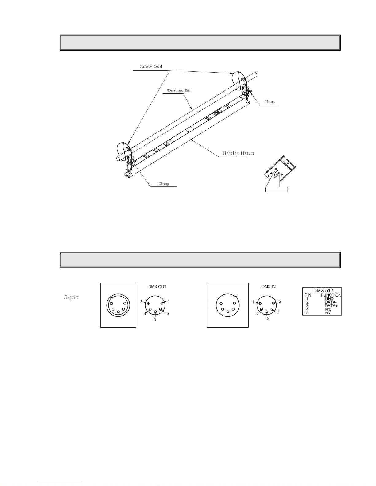
INSTALLTHE LIGHTING FIXTURE
When the lighting fixture is used, as the right figure above, unfold the support to certainangle and put the lighting fixture onto a
flatsurface.Makesureitissteady.
When the lighting fixture is used at a high place, asthe left figure above, fold the support, turnit round to the top ofthe lighting
fixture, connect a lamp hook to the mounting hole reserved in the support by screws, and then hang the hook to a high place.
Eventually, use the safetycord provided to pass through the handles and hang it as asecond safety fixing.
CONTROLSYSTEMAND POWER CONNECTION
Connection between the controller and a lighting fixture and between one lighting fixture and another must be made with a 2
core-screened cable, with each core having at least a 0.5mm diameter. Please use the lighting fixture’s cannon5- pin signal input and
outputcablesasconnection.The 5-pinsignalconnectionsareconnectedasshown inthefigureabove.
Note:Care shouldbetaken toensure thatnone ofthepins touchthemetallicbodyoftheplugor eachother. The bodyoftheplugisnot
connectedinanyway.ThedeviceacceptsdigitalcontrolsignalsinprotocolDMX512(1990).
As for power connections, each lighting fixture has to be supplied separately byexternal power. Use the power cord of each lighting
fixture to connect the mains power directly, making sure the voltage and frequency markedon the panel of the lighting fixture match
what is supplied.

5/12
Theconnections areas thefigurebelow.
DMXTERMINATOR
In the Controller mode, at the last fixture in the chain, the DMX output has to be connected with a DMX terminator. This prevents
electrical noise fromdisturbingandcorruptingthe DMXcontrol signals.
The DMX terminator is simply an XLR connector with a 120Ω(ohm) resistor connected across pins 2 and 3, which is then plugged
intotheoutputsocketonthe lastlighting fixtureinthechain.The connectionsare illustratedbelow.
6/12
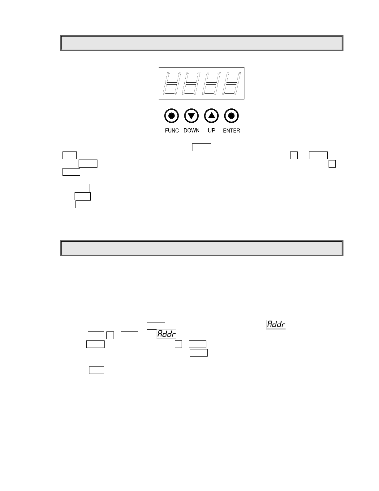
SETUPOPTIONS-LIGHTING FIXTURE CONFIGURATION
To browse through or change a fixture’s configuration, after
ENTER button has been
pressed for about 3 seconds, the display of
AddR means the entrance of the menu. To set or browse through a fixture’s settings, press buttons of UP and DOWN. After
button ENTER is pressed, a sub-menu is entered showing current parameters while indication flashing.
Press button UP or
DOWN tochangevalues(plusorminus)
Pressbutton
ENTER
to saveyour settingsorenterintotheupper level menuand theindication stops fromflashing.
Press
FUNC toenterinto theupperlevelmenu(parametersnotsaved)orbrowsethroughthe upperlevelmenu.
After FUNC is pressed for more than 1second or buttons notpressed for more than 1 minute, it will go back to the main menu
displaying thefixture’sname.
Aftertheexitofthemenus,thecurrentlampcolorwillbeshown.
WhileDMX signalsareavailable,SignalLEDindication willbe on,otherwiseoff..
TO SETTHE DMX STARTADDRESS
Eachdevice must be given a DMX start address so that the correct lighting fixture responds to the correct control signals. This DMX
start address is the channel number from which the lighting fixture starts to “listen” to the digital control information being sent out
from the controller. The device has Two Channel Modes. 1 Channel Mode has 1 channel, so set the No. 1 lighting fixture’s address
001,No. 2lightingfixture’saddress002,No.3 lighting fixture’saddress003,and soon.4 ChannelModehas4channels, soset the No.
1lighting fixture’saddress001,No.2lightingfixture’saddress005, No.3 lightingfixture’s address009,andsoon.
Launch the lighting fixture. Pressbutton ENTER formorethan3 secondsto unlockthepaneltill
isdisplayed
.
Pressbutton FUNC, UPor DOWN to find“ ”menu.
Thenpress ENTER to showDMXaddressandpress UP or DOWN to setDMXaddress.
Atthis time, the address will flashcontinuously.Pressbutton ENTER to confirmand it means the setting has been
enabled and saved. After powered next time, the latest setting will be used.
Pressbutton FUNC,it willreturnto theupper menu onebyone.

7/12
DMX PROTOCOL
1ChannelMode
Channel FUNCTION DMX DESCRIPTION
1 Dimmer 000-255 Dimming
4ChannelMode
Channel
FUNCTION
DMX
DESCRIPTION
1 Thefirstpart Dimmer 000-255 Dimming
2 Thesecondpart Dimmer 000-255 Dimming
3 Thethirdpart Dimmer 000-255 Dimming
4 Theforthpart Dimmer 000-255 Dimming
INDICATION OF LED CHARACTER
DMXIndication On DMX signalOK
Off No DMXsignal

8/12
MAINTENANCE
To prolong the life of the lighting fixture, it is very important to do the maintenance work. Cooling fans must be cleaned once every
15days and external lens cleaned periodically for an optimum light output. DO NOT USE ANY SOLVENT CONTAINING
CHEMICALELEMENT.
Cleaning frequencydependsontheenvironment inwhichthe fixture operates.Softclothandtypical glasscleaning productsshouldbe
used forcleaningwith care.Itisrecommended tocleanlightingfixture atleastonceevery20days.
Donotuseanyorganicsolvent,e.g.alcohol,tocleanhousingoftheapparatus.
TROUBLESHOOTING
PROBLEM ACTION
The lightingfixturedoesn’t switchon
Powerconnectionisnotcorrect.
Power supply is damaged or abnormal. Call a qualified personnel to fix
it.
Connection of control board is not correct. Call a qualified personnel to
fixit.
The lighting fixturecan be turnedon, but LEDs
donotemitlightandareoutofcontrol.
ConnectionofLED board is notcorrect. Call a qualified personnel to fix
it.
Thelampcomes onbutthelighting fixture
doesn’trespond tothecontroller
Makesurethatthelightingfixture’s StartAddressis properlyset.
Replaceorrepair theXLR signal cable.
Thebeamappearsdim Thelightingfixtureistoohot.Take ventilationmeasurestomake itcool.

9/12
TECHNICALDATA
VOLTAGES:
100-240V AC,50/60Hz
POWERCONSUMPTION:
120W@220V
LEDLightsources:
Quantity 12pcs(10Wx12)
Manufacturers Rated LED Life 50000Hours
DIMMER:
0-100%linearlyadjustable
COLORTEMPERATURE
PR-3500T 3200K
PR-3500D 5600K
CRI
Ra≥86
Luminous Flux
5000 lm
LIGHTANGLE
FieldAngle(
1/10 Maximum) θ0°~80°
CONTROL:
DMX512,5pininterfaces
Two
Channel Modes:
1CH,1
Channel;4CH,4Channels.
HOUSING:
Extrudingaluminum,IP20
WORK ENVIRONMENTTEMPERATURE:
-20°C~40°C
WEIGHT:
Netweight: 4.2kg
Gross weight: 6.8kg

10/12
SIZES:
300±20
300±20
185
80
1800
Electrical Diagram

11/12
COMPONENT ORDER CODES
NAME PARTNO. QUANTITY REMARK
PowerSwitch
192010134 1
10WLEDWhite
150020255
1
2
CT3200KforPR
-
3
5
00T
10WLEDWhite
15002025
2
1
2
CT5500KforPR
-
3
5
00D
PR-3500 ControlBoard(W)
230060
309
1

12/12
PR LIGHTING LTD.
PR New Hi-tech Science Park, 1582 XingyeAvenue
NancunPanyu,Guangzhou, 511442China
TEL:+86-20-39952888
FAX:+86-20-39952330
P/N:320020125A
Version:20140711
This manual suits for next models
1
Table of contents
Other PR Lighting Equipment manuals


Popular Lighting Equipment manuals by other brands

Clevertronics
Clevertronics L10 LVP2LEDM-P Series Installation & maintenance instructions

Lucci CONNECT
Lucci CONNECT GECKO 221076 installation instructions

EMG
EMG EMG-H-X Installation information

Robin
Robin Robin MiniMe user manual

PR Lighting
PR Lighting XL 1500 user manual

RGB Laserverkoop
RGB Laserverkoop XS2500 user manual


