Tapeswitch GS-120 User manual

Release 7/2009 Ver. 1.0 Technical Manual: GS-120 Light Curtain Systems
GS-120 Photo-Electric Light Curtain Systems
Technical Manual
WARNING
Tapeswitchphoto-electric safetysystemsareintendedtoprotect operatorsworkingatornear
dangerous machinery. They can only perform this function if they are correctly fitted to a
suitable machine. It is essential that the full contents of this manual and all the international
documents referred to herein are fullyunderstood before any attempt at installationis made.
If in doubt, contact Tapeswitch Corporation.
IMPORTANT
This manual must accompany the product throughout its working life. Those persons
responsible for the product must ensure that all persons involved in the installation,
commissioning, operation, maintenance and servicing of the product have access to all the
information supplied by the manufacturers of the machine and its safety system.

Release 7/2009 Ver. 1.0 Technical Manual: GS-120 Light Curtain Systems
TAPESWITCH CORPORATION Phone: 631-630-0442
100 Schmitt Boulevard 2Fax: 631-630-0454
Farmingdale, New York 11735 www.tapeswitch.com
TABLE OF CONTENTS
1.0 GENERAL
1.1 INTRODUCTION 4
1.2 PRODUCT Range 4
1.2.1 General 4
1.2.2 Detection Capability 5
1.2.3 Protected Heights 5
1.2.4 Accessories 5
1.2.4.1 Mirror Units 5
1.2.4.2 Mounting Stands 7
1.3 ORDERING INFORMATION 7
1.3.1 GS-120 Light Curtain Order Code 8
1.32 GS-120 Multi-Beam Order Code 8
1.3.3 Cable Options 9
1.3.4 Interface and Programming Units 9
2.0 TECHNICAL DESCRIPTION 9
2.1 CURTAIN 9
2.2 COMMUNICATIONS 10
2.3 TEST INPUT 10
2.4 INDICATORS 11
2.4.1 LED Option 11
2.4.2 Diagnostic Option 12
3.0 INSTALLATION 13
3.1 GENERAL 13
3.2 MECHANICAL INSTALLATION 13
3.2.1 General Considerations 13
3.2.1.1 Multi-Sided Guarding 15
3.2.2 Curtain Dimensions 16
3.2.2.1 GS-120 Basic System 16
3.2.2.2 GS-120 Multi-Beam System 17
3.2.2.3 GS-120 Cascaded System 18
3.2.3 Separation Distance 19
3.2.3.1 Normal Approach 19
3.2.3.2 Parallel Approach 21
3.2.3.3 Angled Approach 22
3.2.3.4 Approach to ‘L’ Installation 22
3.2.4 Optical Alignment 23
3.2.5 Reflective Surfaces 23
3.2.6 Systems in Close Proximity 24
3.2.7 Mounting Brackets 24
3.3 ELECTRICAL INTERFACE, OPERATION, AND INSTALLATION 27
3.3.1 General 27
3.3.2 Emitter Unit 27
3.3.2.1 General 27
3.3.2.2. Test Input 28
3.3.3 Receiver Unit 28
3.3.3.1 General 28
3.3.3.2 PNP Version 29
3.3.3.3 SSR Version 30
3.3.4 Interfacing to a Machine 31
3.34.1 PNP Version Manual Reset 31
3.34.2 PNP Version Auto Reset 32
3.34.3 SSR Version 33
3.4 INITIAL CHECKING AND ALIGNMENT 34
4.0 INTERFACE AND AUXILIARY UNITS 35
4.1 GENERAL 35
4.1.1 Methods of Interfacing 35
4.1.2 Special Interfacing Considerations 36

Release 7/2009 Ver. 1.0 Technical Manual: GS-120 Light Curtain Systems
TAPESWITCH CORPORATION Phone: 631-630-0442
100 Schmitt Boulevard 3Fax: 631-630-0454
Farmingdale, New York 11735 www.tapeswitch.com
4.1.2.1 PNP Version Manual Reset 36
4.1.2.2 PNP Version Auto Reset 36
4.1.2.3 SSR Version 36
4.1.3 Connections to an AS-i System 37
5.0 PERIODIC CHECKING, SERVICING, AND MAINTENANCE 38
5.1 PERIODIC CHECKING 38
5.1.1 Commissioning Checks 38
5.1.2 6 or 12 Month Periodic Checks 38
5.1.3 Daily/Setting Examination 39
5.1.4 Checking Detection Capability 39
5.1.4.1 GS-120 System 39
5.1.4.2 GS-120 Multi-Beam System 40
5.2 SERVICING 41
5.3 MAINTENANCE 41
6.0 TECHNICAL SPECIFICATIONS (GS-120Series Emitter & Receiver) 42
APPENDIX A: BSRSA INTERFACE UNIT 43
APPENDIX B: BSRUA-2 INTERFACE UNIT 49
APPENDIX C: SRUB INTERFACE UNIT 57
APPENDIX D: SRUS INTERFACE UNIT 63
APPENDIX E: C6 MULTIFUNCTION INTERFACE CONTROLLER 67
APPENDIX F: GDC-1 24 VDC POWER SUPPLY 68
APPENDIX G: LAT LASER ALIGNMENT TOOL 69

Release 7/2009 Ver. 1.0 Technical Manual: GS-120 Light Curtain Systems
TAPESWITCH CORPORATION Phone: 631-630-0442
100 Schmitt Boulevard 4Fax: 631-630-0454
Farmingdale, New York 11735 www.tapeswitch.com
1.0 GENERAL
1.1 INTRODUCTION
Tapeswitch GS-120 light curtains are through-beam
photo-electric machine guarding devices, designed to
protect operators working at or near dangerous
machinery. They meet the requirements for EN61496
Type 2 light curtains and Category 3 safety control units
as defined in EN954-1.
When correctly installed on a suitable machine, the
system will detect a person (or part of aperson)entering
a dangerous area in the vicinity of the machine, and will
signal the dangerous motion to cease before that
person can reach a position where injury could occur.
Tapeswitch GS-120 light curtains use infra-red
technology. A curtain of infra-red light is projected
across the dangerous area. Intrusion into this curtain by
a person or part of a person will be detected by the
system. This will cause safety output signals to be
generated which will stop the dangerous motion of the
machine.
WARNING
The information in this manual relates to the
use of the basic GS-120 light curtain, to provide
a basic safety switching device.
In some applications, a GS-120 light curtain
may be used together with other Tapeswitch
equipment to provide additional functions and
features. The additional information necessary
for the correct use of a GS-120 light curtain
when used with other Tapeswitch equipment is
provided within this manual.
In such cases, some installation parameters,
notably the mounting position of the light
curtain in relation to the dangerous part of the
machine, can be affected and close attention
must be paid to all the information supplied
with all equipment.
INTERNATIONAL CONSIDERATION: Theheritage of
the Tapeswitch GS-120 system is strongly grounded in
international commerce and standards. They were
developed by Tapeswitch Ltd., of Chorley, England.
Both Tapeswitch Ltd. and Tapeswitch U.S. are part of
Indel Corporation, a private U.S industrial group. The
GS-120 product line was developed to meet published
and proposed safety standards for the United States,
Germany, England, Finland, and Sweden,as wellasthe
common market unified standard. GS-120 systems are
manufactured both in England and the United States.
Tapeswitch GS-120 products have been independently
third party tested to IEC 61496 by BG, and are certified
to this standard (CE approval/certification). Contact
Tapeswitch for more details.
Tapeswitch can provide additional assistance to
customers wishing to use GS-120 guards in
international applications. Some foreign language
technical manuals are available.
1.2 PRODUCT RANGE
1.2.1 GENERAL
The GS-120 light curtains are available in a range of
different protected heights and detection capabilities.
These two parameters are known by many other names
and therefore it may be useful to define them here, as
they are intended to be used in this manual. To make
this clearer it is also necessary to define two further
parameters, detection zone and operating range:
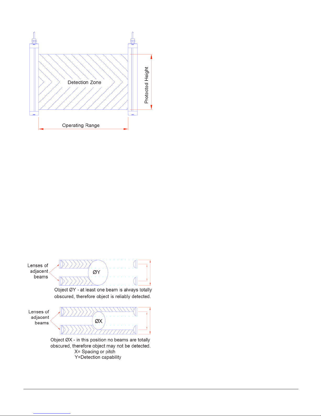
Detection Zone: This is the actual curtain of infra-red
light generated between the emitter and receiver units
within which an appropriately dimensionedobject will be
reliably detected and, for the GS-120, can be
considered to be a two dimensional, rectangular plane
(see Figure 1).
Operating Range: One dimension of the detection
zone rectangle is given by the distance between the
emitter and receiver units. This is the operating range
(see Figure 1).
Protected Height: The other dimension of the
detection zone rectangle is commonly known as the
protected height. The word “height” has been adopted
in the latest standards for this equipment because most
curtains are mounted vertically. The protected height is
often related to, but is not the same as, the length of the
emitter and receiver units (see Figure 1).
Release 7/2009 Ver. 1.0 Technical Manual: GS-120 Light Curtain Systems
TAPESWITCH CORPORATION Phone: 631-630-0442
100 Schmitt Boulevard 5Fax: 631-630-0454
Farmingdale, New York 11735 www.tapeswitch.com
Figure 1
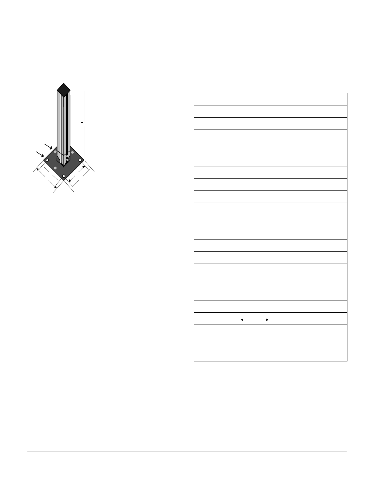
Detection Capability: This is the minimum dimension
of an opaque object which will be reliably detected
anywhere within the detection zone.
NOTE: The spacing or pitch of the beams or lenses in a
light curtain is not the same as the detection capability.
The detection capability is always greater than the
spacing or pitch. Spacing or pitch should not be used in
the calculation of separation distances (see Figure 2).
1.2.2 DETECTION CAPABILITY
GS-120 light curtains are available with detection
capabilities of 30mm or 70mm.
Figure 2
1.2.3 PROTECTED HEIGHTS
GS-120 light curtains are available with nominal
protected heights as follows:
Detection Capability Nominal protected heights
(in mm and inches)
30mm (1-3/16 in.) 200-300-400-600-800-900-
1000-1200-1400-1600 mm
(8-12-16-24-32-36-40-48-56-
64-72 inches)
70mm (2-3/4 in.) 600-800-1000-1200-1400-
1600-1800 mm
(24-32-40-48-56-64-72
inches)
The minimum separation distance is 0.5 m.
Note:
The actual protected height is 8 mm greater than the
nominal protected height.
1.2.4 ACCESSORIES
1.2.4.1 Mirror Units
A range of mirror units are available to enable a single
curtain to be used to guard two or three sides of a
machine or to avoid structural obstructions.
The mirror assembly consists of a high quality silver-
backed glass mirror adhesively attached to a length of
extruded aluminum. Two pivot brackets are bolted to
the aluminum extrusion and can be adjusted anywhere
along the length for mechanical attachment. The actual
length of the mirror is 4 inches (1000mm) larger than the
active curtain length to accommodate a wide tolerance
for height alignment. All of the necessary hardware is
supplied to facilitate mounting to the mounting/floor
stands. The dimensions of the pivot brackets, extruded
aluminum and overall mirrors are shown below in
millimeters.

Release 7/2009 Ver. 1.0 Technical Manual: GS-120 Light Curtain Systems
TAPESWITCH CORPORATION Phone: 631-630-0442
100 Schmitt Boulevard 6Fax: 631-630-0454
Farmingdale, New York 11735 www.tapeswitch.com
40mm
6.8mm
40mm
6.8mm
X
Glass Reflective
Surface
Overall Length =
Protective Height + 4"
180°Rotation
in this Plane
Pivot Brackets
(180°Rotation;
Distance X is Adjustable)
Supplied with:
1. 1-40mm x 40mm extrusion, 100mm larger than
protective height.
2. 1-silver backed mirror, 100mm larger than
protective height.
3. 2-pivot joints.
4. 2-40mm x 40mm end covers.
5. 4-5mm T slot nuts.
6. 4-#12 flat washers.
7. 4-5mm spring washers.
8. 4-5mm x 5/8 hex bolts.
Curtain Lengths Mirror Assembly
Length P/N
200mm - 8" 300mm - 12" 0960
300mm - 12" 400mm - 16" 0961
400mm - 16" 500mm - 20" 0962
600mm - 24" 700mm - 28" 0963
800mm - 32" 900mm - 36" 0964
900mm - 36" 1000mm - 40" 0965
1000mm - 40" 1100mm - 44" 0966
1200mm - 48" 1300mm - 52" 0967
1400mm - 56" 1500mm - 60" 0968
Pivot Bracket
Extrusion Dimensions
For units greater than 56 inches, custom mirrors are available.
Release 7/2009 Ver. 1.0 Technical Manual: GS-120 Light Curtain Systems
TAPESWITCH CORPORATION Phone: 631-630-0442
100 Schmitt Boulevard 7Fax: 631-630-0454
Farmingdale, New York 11735 www.tapeswitch.com
3/8" holes
3 leveling bolts
P/N 0957
Supplied with:
1. 5 ft.item 40mm X40mm extrusion
2. 1-base stand.
3. 1-40mm X40mm end cap.
4. 2-T slot nuts M5.
5. 2-M5 X12mm hexhead.
6. 2-M5 spring lock washers.
7. 2-flatwashers 5/5.3mm.
8. 2-5/16 bolts.
9. 3-3/8 24 x1/2"hexhead.
5"
5"
5
4"
4"
1.2.4.2 Mounting Stands
Floor mounting stands are available for use where the
guard cannot be mounted directly to the machine.
The mounting stand set includes a floor-mounted base
into which the 5-foot mounting post can be secured.
The floor base is steel and can bepermanentlymounted
to the floor surface with the pre-drilled mounting holes.
The post is extruded aluminum with slots to allow the
light curtain to be positioned anywhere along its length.
The mounting stands are supplied with all of the
necessary hardware to facilitate mounting a standard
GS-120 light curtain. Leveling bolts allow for minor
adjustments to the floor stand orientation.
1.3 ORDERING INFORMATION
Part numbers for the various models are shown in the
table on the right. To fully specify a model and its
options use an order code as shown in sections 1.3.1
and 1.3.2 on the following page.
Model Number Part Number
GS-120/8”(208mm)/30 0801
GS-120/12”(308mm)/30 0802
GS-120/16”(408mm)/30 0803
GS-120/24”(608mm)/30 0804
GS-120/32”(808mm)/30 0805
GS-120/36”(908mm)/30 0806
GS-120/40”(1008mm)/30 0807
GS-120/48”(1208mm)/30 0808
GS-120/56”(1408mm)/30 0809
GS-120/64”(1608mm)/30 0810
GS-120/72”(1808mm)/30 0811
GS-120/24”(608mm)/70 0821
GS-120/32”(808mm)/70 0822
GS-120/40”(1008mm)/70 0823
GS-120/48”(1208mm)/70 0824
GS-120/56”(1408mm)/70 0825
GS-120/64”(1608mm)/70 0826
GS-120/72”(1808mm)/70 0827
GS-120-4 0828
GS-120-3 0829
GS-120-2 0830
Release 7/2009 Ver. 1.0 Technical Manual: GS-120 Light Curtain Systems
TAPESWITCH CORPORATION Phone: 631-630-0442
100 Schmitt Boulevard 8Fax: 631-630-0454
Farmingdale, New York 11735 www.tapeswitch.com
1.3.1 GS-120 LIGHT CURTAIN ORDER CODE
GS120 / XXX / X / XXXX / XX / XXXX / XX
Outputs:
PNP = 2 x PNP outputs
SSR = 2 x Solid-State Relays
Curtain Type:
S = Single Unit
M = Master Unit
A = Slave Unit
D = Double-Ended Slave Unit
Curtain Length:
200 mm to 1800 mm
Detection Capability:
30 mm or 70 mm
Curtain Display:
LED - Discrete LEDs
DIAG - Dot Matrix Diagnostic Display
Bracket options:
CB = Clamp Bracket
AB = Adjustable Bracket
EB = End Cap Bracket
1.3.2 GS-120 MULTI-BEAM ORDER CODE
GS120 / XXX / X / X / XXXX / XX
Outputs:
PNP = 2 x PNP outputs
SSR = 2 x Solid-State Relays
Curtain Type:
S = Single Unit
M = Master Unit
A = Slave Unit
D = Double-Ended Slave Unit
Number of Beams:
2
3
4
Curtain Display:
LED - Discrete LEDs
DIAG - Dot Matrix Diagnostic Display
Bracket options:
CB = Clamp bracket
AB = Adjustable bracket
EB = End cap bracket

Release 7/2009 Ver. 1.0 Technical Manual: GS-120 Light Curtain Systems
TAPESWITCH CORPORATION Phone: 631-630-0442
100 Schmitt Boulevard 9Fax: 631-630-0454
Farmingdale, New York 11735 www.tapeswitch.com
1.3.3 CABLE OPTIONS
Cable assemblies are used to connect the GS-120
emitter and receiver units to a controller or machine.
The emitter has a 5-wire cable and the receiver has an
8-wire cable. One end of each cable has a keyed quick-
disconnect connector and the other end is unterminated.
The cables are IP68 rated, and UL and CSA
recognized.
Order cable options using the following part numbers:
Description Part Number
Emitter Cable, 15 ft, 5 Conductor 0972
Emitter Cable, 30 ft, 5 Conductor 0973
Emitter Cable, 98 ft, 5 Conductor 0976
Receiver Cable, 15 ft, 8 Conductor 0974
Receiver Cable, 30 ft, 8 Conductor 0975
Receiver Cable, 98 ft, 8 Conductor 0977
1.3.4 INTERFACE AND PROGRAMMING
UNITS
(See electrical interface and operation for technical
details)
Order interface and programming units using the
following part numbers:
Model Description Part Number
BSRSA Wall-mounted box
110/240 Vac or 24 Vdc 0950
BSRUA-2 DIN rail mount
110/240 Vac or 24 Vdc 0951
SRUB DIN rail mount
24 Vdc 0952
SRUS DIN rail mount
24 Vdc 0949
C6 Wall-mounted box
Multi-zone 0480
GDC1 24 Vdc power supply 0953
LAT Laser alignment tool 0956
2.0 TECHNICAL DESCRIPTION
2.1 CURTAIN
A basic GS-120 light curtain consists of two units: an
emitter unit and a receiver unit. Both units are identical
in shape and size. The units are enclosed in a robust
extruded aluminum section with reinforced composite
end covers.
The emitter and receiver units together generate a
curtain of infra-red light between them. This curtain is
mounted in such a position in relation to the dangerous
parts of a machine that a person or part of a person
approaching those dangerous parts must first penetrate
the curtain. This penetration is detected by the light
curtain system and, by means of its output switching
devices, the light curtain system causes the dangerous
parts to go to a safe state (e.g. by stopping moving
parts) before the person can reach them.
IMPORTANT
From the information above, it can be seen
that safe use of a light curtain relies not only
on the safety integrity of the curtain itself but
also on its proper mechanical and electrical
interfacing to the machine.
The safety integrity of the light curtain itself is
the responsibility of Tapeswitch and the
remainder of this section describes the
features of the design by which safety
integrity is ensured.
Proper mechanical and electrical interfacing
of the overall system is the responsibility of
the user. Comprehensive information for this
purpose is provided in sections 3 and 4 of
this manual.
The emitter unit contains a number of infra-red light
emitting diodes (LEDs). The quantity and spacing of
these LEDs depends on the protected height and the
detection capability of the particular light curtain. The
devices are arranged equally-spaced in an array.
The receiver unit contains a corresponding number of
infra-red photodiodes similarly arranged.
Release 7/2009 Ver. 1.0 Technical Manual: GS-120 Light Curtain Systems
TAPESWITCH CORPORATION Phone: 631-630-0442
100 Schmitt Boulevard 10 Fax: 631-630-0454
Farmingdale, New York 11735 www.tapeswitch.com
Each LED and photodiode is fitted with a precision lens,
which produces an evenly intense, slightly diverging
beam of infra-red light from each LED and an evenly
sensitive, slightly converging ‘reception cone’ into each
photodiode. This arrangement provides a high signal-
to-noise ratio and maximum operating range for the
system together with ease of alignment and rejection of
extraneous reflected light sources.
The function of each LED and photodiode is controlled
by its own dedicated, specially-designed ASIC
(Application Specific Integrated Circuit). All the circuitry
necessary for the operation of an LED or photodiode is
contained within this single component, resulting in a
very low component count and consequent
improvement in system reliability.
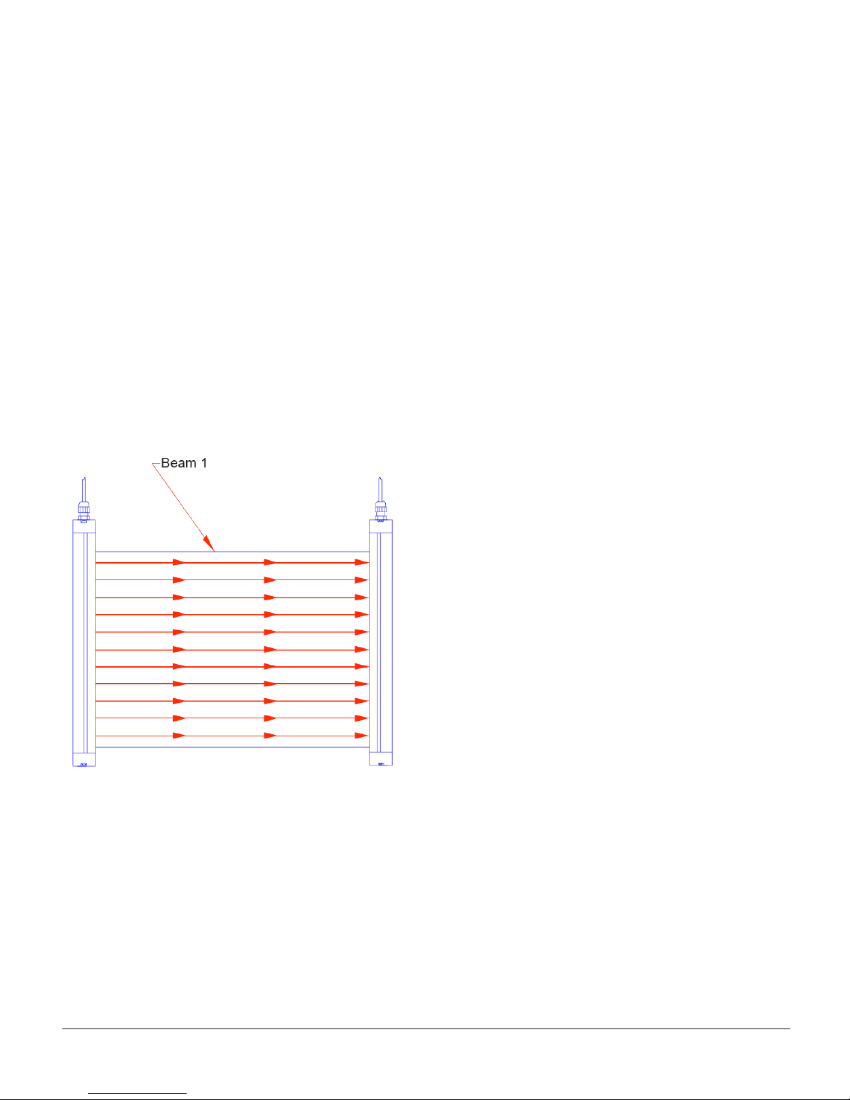
For each LED in the emitter unit there is a
corresponding photodiode at the same relative position
in the receiver unit. Each LED/photodiode pair makes a
‘beam’ and the curtain is made up of a number of such
beams, all parallel to each other. (See Figure 3.)
Figure 3
Only one LED and one photodiode are active at any
time. The emitter unit runs independently from the
receiver unit. There are no connections between the
units.
The emitter unit activates each of its LEDs in turn and
the receiver unit synchronizes with the emitter unit.
Each receiver ASIC, in its turn, generates an output
signal which is proportional to the level of infra-red it
receives from its corresponding LED. Signals from
other sources, such as background lighting, are filtered
out inside the ASIC.
There is one microprocessor in the emitter unit and two
in the receiver unit. All three microprocessors perform
exhaustive checks on their own hardware and software,
prior to and during operation.
The two in the receiver unit continually communicate
their results to each other such that if a fault occurs in
one device the other can shut the system down.
In the receiver unit there are two independent switching
channels each containing an output signal switching
device (OSSD). Each of the two microcontrollers in the
receiver unit controls one of these OSSDs and monitors
the other.
The OSSDs are very robust solid state devices. These
devices are intended to be connected directly to the
machine control system, a Tapeswitch interface unit or
a suitable safety relay such that if one or both of them
are in the OFF state, the machine will go to or remain in
a safe condition, for example, by stopping dangerous
motion or bypreventing dangerousmotionfromstarting.
2.2 COMMUNICATIONS
The receiver unit incorporates a serial communications
port. Various auxiliary Tapeswitch units can be
connected to this port for the purposes of programming
functions within the light curtain and for interrogatingthe
system.
No equipment other than Tapeswitch brand should be
connected to this port. Full instructions for the use of
this port with auxiliaryequipmentareprovided within this
manual.
2.3 TEST INPUT
A pair of terminals is provided across which a pair of
normally closed, volt free contactsshould be connected.
When these contacts are opened the emitter unit will
stop scanning, forcing the OSSDs to the OFF state.
This input simulates a curtain obstructed condition.
NOTE: This input is provided to allow the GS-120 to be
used with machine control systems which need to cycle
thesafety circuit prior tooperation. The GS-120system
itself does not require this input to be used. If this input
is not used it should be jumpered and remain jumpered
at all times.

Release 7/2009 Ver. 1.0 Technical Manual: GS-120 Light Curtain Systems
TAPESWITCH CORPORATION Phone: 631-630-0442
100 Schmitt Boulevard 11 Fax: 631-630-0454
Farmingdale, New York 11735 www.tapeswitch.com
2.4 INDICATORS
2.4.1 LED OPTION
The standard/master receiver unit has four status
indicators as shown in Figure 4. The standard/master
emitter unit has two status indicators as shown in
Figure 5. The slave emitter and receiver have one
status indicator as shown in Figure 6.
A description of each indicator is given in Table 1.
Figure 5
Standard & Master Emitter
Figure 4
Standard & Master Receiver
Figure 6
Slave Emitter & Receiver
Table 1 – LED Indicator Descriptions
Release 7/2009 Ver. 1.0 Technical Manual: GS-120 Light Curtain Systems
TAPESWITCH CORPORATION Phone: 631-630-0442
100 Schmitt Boulevard 12 Fax: 631-630-0454
Farmingdale, New York 11735 www.tapeswitch.com
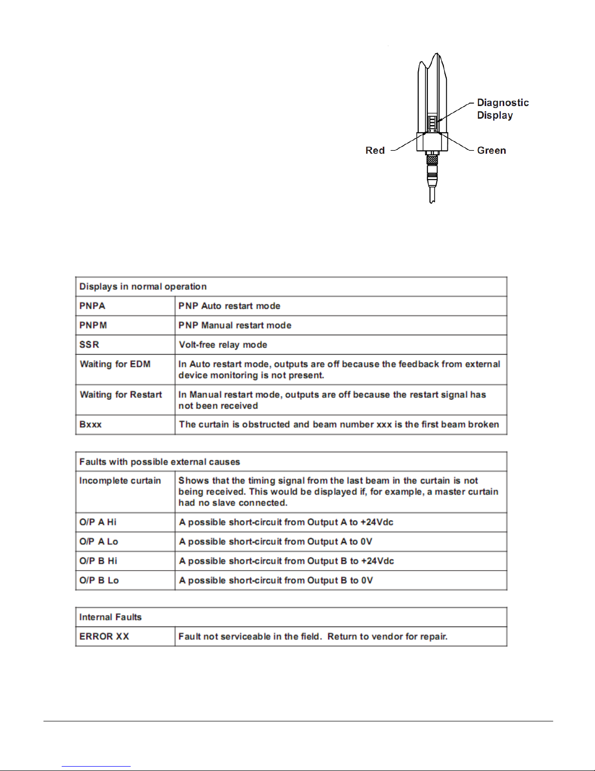
2.4.2 DIAGNOSTIC OPTION
For this option, the LED indicators on the standard and
master emitter units and all slave units are the same as
shown for the LED option above in Figures 4, 5, and 6.
However, the standard and master receiver units
contain a scrolling 4-digit alphanumeric display, shown
in Figure 7, which is used for diagnostic purposes.
The various displays and their meanings are shown in
Table 2.
Figure 7
Diagnostic Receiver
Table 2 – Diagnostic Displays

Release 7/2009 Ver. 1.0 Technical Manual: GS-120 Light Curtain Systems
TAPESWITCH CORPORATION Phone: 631-630-0442
100 Schmitt Boulevard 13 Fax: 631-630-0454
Farmingdale, New York 11735 www.tapeswitch.com
3.0 INSTALLATION
3.1 GENERAL
WARNING
Tapeswitch GS-120 systems are designed to
protect operators working at or near
dangerous machinery. Theycan onlyperform
this function if they are correctly fitted and
interfaced to a suitable machine. Those
persons responsible for the machine must
ensure that all persons involved in the
installation of the photo-electric safety
system have the necessary knowledge,
training and experience and that theyarefully
aware of all laws, rules, regulationsand codes
of practice pertaining to their task.
The attention of the installer is drawn to following
general requirements for the installation of a GS-120
system:
(a) The dangerous motion of the machine must be
electrically controllable.
(b) The machine response/stopping performance must
be adequate and consistent.
(c) It must be possible to stop the dangerous motion of
the machine at any point in its operation, in any
operating mode.
(d) The control system as a whole must be designed
and constructed to provide the appropriate category of
safety integrity as defined in EN954-1 'Safety of
machinery: Principles for the design of safety related
control systems'. The appropriate categoryshouldbeas
prescribed in the relevant C type EN standard for the
type of machine concerned. In the absence of such a
standard the appropriate category of safety integrity
should be determined by performing a risk assessment
as described in EN1050 'Safety of machinery: Risk
assessment
(e) Steps must be taken to prevent access to the
dangerous parts of the machine from any direction not
covered by the photo-electric curtain. Such steps could
include fixed or interlocking fences or screens,
additional photo-electric devices or pressure sensitive
mats. Similar steps should be taken to preventa person
from standing between the curtain and the dangerous
parts of the machine.
(f) No devices other than those specified in this manual
should be connected to the internally-generated power
supply of the system.
(g) After installation, the machine/guardsystem mustbe
commissioned in accordance with the requirements of
section 5.1.1 of this manual.
(h) Any covers removed during installation must be
replaced as soon as possible.
(i) At power on, after a power interruption or after the
curtain has been actuated, it must not be possible for
the machine to start (or restart) until a manual control
has been operated. This is known as “start/restart
interlock”. The GS-120 can provide this function, but if it
is not installed, it must be provided elsewhere within the
safety system
(j) To avoid nuisance tripping, if a fluorescent lamp with
an electronic ballast is located within 5 feet (1.5 meters)
of the receiver unit, it must be outside of a 20º field of
view from the receiver unit (±10º about the center line).
If this is not practical, a 60 Hz fluorescent light fixture
should be used.
3.2 MECHANICAL INSTALLATION
3.2.1 GENERAL CONSIDERATIONS
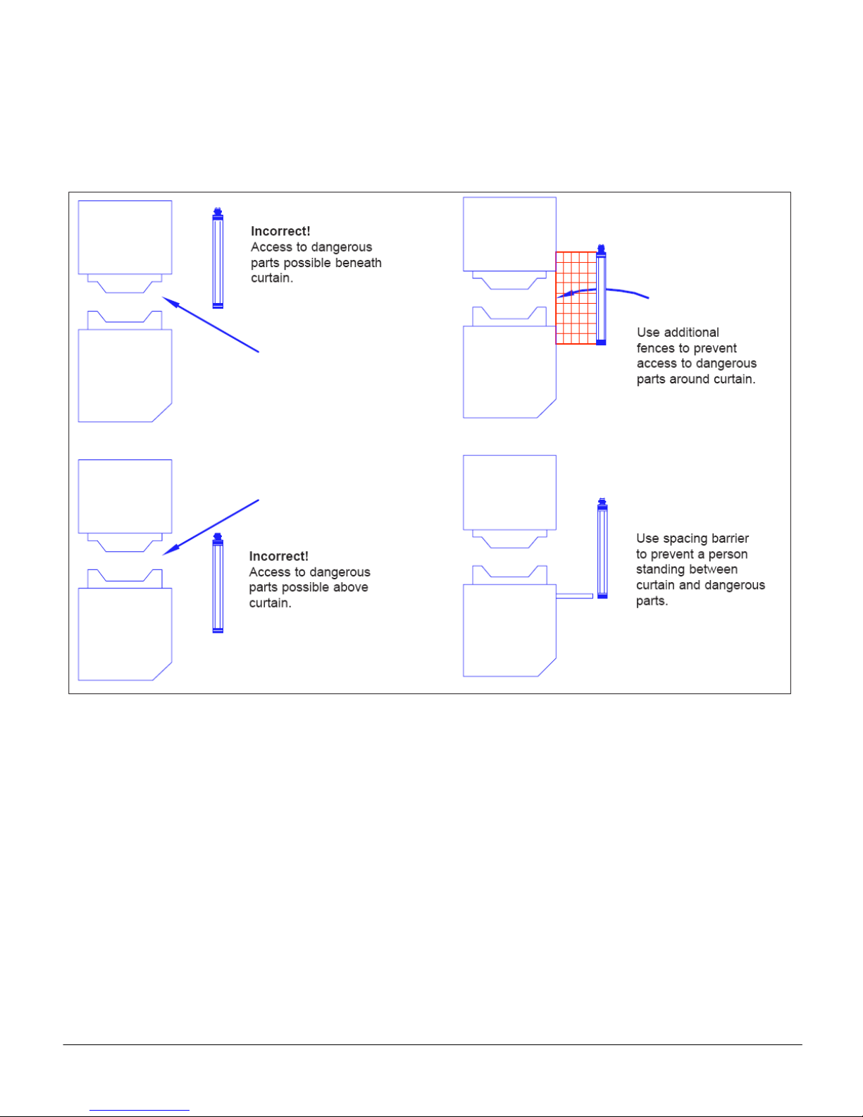
ANSI B11.19-1990 gives guidance on the dimensions
and positioning of photo-electric safety devices fitted to
industrial machines. The main considerations are
described below and are illustrated in Figure 8.
(a) The appropriate protected height must be selected.
The curtain must be of sufficient height such thataccess
to thedangerous parts, from the directionofapproach of
the operator, is only possible by obstructing the curtain
taking into account all possible operator positions.
(b) The correct minimum separation distance must be
observed. The curtain must be mounted in the correct
position in relation to the dangerous parts of the
machine to take account of the stopping performanceof
the machine, the curtain format used and the detection
capability of the curtain.
(c) Steps must be taken to prevent access to the
dangerous parts from any direction not covered by the
curtain and to prevent an operator from standing
between the curtain and the dangerous parts without
obstructingthe curtain. Additionalmechanical guarding
will usually be necessary to achieve this.
Release 7/2009 Ver. 1.0 Technical Manual: GS-120 Light Curtain Systems
TAPESWITCH CORPORATION Phone: 631-630-0442
100 Schmitt Boulevard 14 Fax: 631-630-0454
Farmingdale, New York 11735 www.tapeswitch.com
The physical parameters affecting the positioning are
the dimensions of the detection zone of the light curtain
(i.e. the protected height and the range) and the
minimum separation distance. These are described in
the following sections.
Figure 8
Release 7/2009 Ver. 1.0 Technical Manual: GS-120 Light Curtain Systems
TAPESWITCH CORPORATION Phone: 631-630-0442
100 Schmitt Boulevard 15 Fax: 631-630-0454
Farmingdale, New York 11735 www.tapeswitch.com
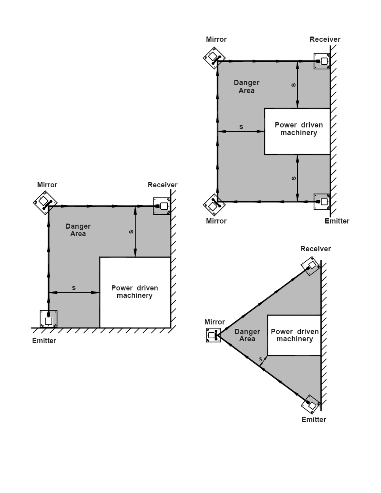
3.2.1.1 Multi-Sided Guarding
By using mirror columns the light curtain beams can be
deflected around corners to form two and three sided
guard configurations. It should be borne in mind that for
each mirror used therange is reduced by approximately
20%. Also the alignment of systems with mirrors can be
difficult especially where the mounting surfaces are
uneven. It is therefore recommended that no more than
two mirrors are used between any pair of emitter and
receiver units. See Figures 9, 10, and 11 for different
multi-sided guarding configurations.
Note: The arrangement shown in Figure 11 is not
recommended, as it is very difficult to determine thatthe
safety distance S is correct.
Figure 9 - Guarding a two-sided area
Figure 10 – Guarding a 3-sided area
Figure 11 – Incorrect use of two-sided guarding

Release 7/2009 Ver. 1.0 Technical Manual: GS-120 Light Curtain Systems
TAPESWITCH CORPORATION Phone: 631-630-0442
100 Schmitt Boulevard 16 Fax: 631-630-0454
Farmingdale, New York 11735 www.tapeswitch.com
3.2.2 CURTAIN DIMENSIONS
3.2.2.1 GS-120 Basic System
The curtain dimensions are defined by the protected
height and the range (i.e. the distance between the
emitter and receiver units). The protected height must
be selected to suit the application. The minimum range
for all systems is 500 millimeters. The maximum range
for systems with 30mm or 70mm detection capability is
15 meters (50 feet).
All the dimensions relating to the curtain, for each of the
GS-120 systems are shown in Figure 12. The upper
and lower boundaries of the curtain are indicated by
arrows on the front window labels of each unit.
Figure 12

Release 7/2009 Ver. 1.0 Technical Manual: GS-120 Light Curtain Systems
TAPESWITCH CORPORATION Phone: 631-630-0442
100 Schmitt Boulevard 17 Fax: 631-630-0454
Farmingdale, New York 11735 www.tapeswitch.com
3.2.2.2 GS-120 Multi-Beam System
All the dimensions relating to the curtain, for
each of the Multi-beam systems (or multi-beam
slave systems) are shown in Figure 13.
Figure 13

Release 7/2009 Ver. 1.0 Technical Manual: GS-120 Light Curtain Systems
TAPESWITCH CORPORATION Phone: 631-630-0442
100 Schmitt Boulevard 18 Fax: 631-630-0454
Farmingdale, New York 11735 www.tapeswitch.com
3.2.2.3 GS-120 Cascaded System
Additional flexibility to facilitate guarding in more than
one plane is provided, by the capability to connect slave
units to a basic or multi-beam master system.
The slave units can be basic or multi-beam systems,
with any of the defined detection characteristics of
30mm or 70mm.
The dimensions relating to the curtains, for each slave
unit are as defined in the previous sections for each
model. The upper and lower boundaries of each curtain
are indicated by arrows on the front window labels of
each unit.
A maximum of two sets of slave units can be connected
to a master system as shown in Figure 14. Each
emitter-receiver pair has a type designation where:
Type GS-120/M is a master
Type GS-120/A is a slave
Type GS-120/D is a slave with a connector at each end
Master and slave units can be assembled up to a
maximum of 240 beams. Where:
30mm detection - 12 beams per 200mm curtain
70mm detection -4 beams per 200mm curtain
Examples:
GS-120/M/1000/30 = 60 beams
GS-120/A/0400/70 = 8 beams
So, total = 68 beams
Notes:
1. When master/slave emitter-receiver sets have
different range capabilities, these must be
respected when systems are configured.
2. When master/slave emitter-receiver sets have
different detection capabilities, the separation
distance must be calculated and adhered to for
each set separately.
Figure 14

Release 7/2009 Ver. 1.0 Technical Manual: GS-120 Light Curtain Systems
TAPESWITCH CORPORATION Phone: 631-630-0442
100 Schmitt Boulevard 19 Fax: 631-630-0454
Farmingdale, New York 11735 www.tapeswitch.com
3.2.3 SEPARATION DISTANCE
Any machine, regardless of the efficiency of its braking
system, will take a certain time to come to rest after a
stop signal is generated.
The time from the instant that the curtain is broken to
the instant that dangerous motion actually ceases is
called the “overall system response time”. The
dangerous parts will obviously continue to move during
this time. The curtain must therefore be positioned at a
certain minimum distance from the dangerous parts to
prevent a person who has obstructed the curtain from
reaching the dangerous parts beforetheyhave stopped.
This distance is the “minimum separation distance” and
is defined as the distance, in the direction of approach,
between the physical point at which the curtain detects
an obstruction and the nearest dangerous parts.
ANSI B11.19-1990 provides guidelines on how to
determine the minimum separation distance for a given
application. Tapeswitch GS-120 systems are primarily
intended for use in normal approach format where the
curtain is perpendicular to the direction of approach,
although they can be used in parallel and angled
approach formats.
3.2.3.1 Normal Approach
Normal approach format is shown in Figure 15. For
normal approach format the inner edge of the front
window of each unit (i.e. the edge which is nearest to
the machine) should be considered to be the point at
which an obstruction is detected. See plane X as
shown in Figure 15.
The effective sensing field of the device shall be located
at a distance from the nearest recognized hazard such
that the operator or others cannot reach the hazard with
a hand or other body part before stopping of the motion
during the hazardous portion of the machine cycle.
Figure 15
Release 7/2009 Ver. 1.0 Technical Manual: GS-120 Light Curtain Systems
TAPESWITCH CORPORATION Phone: 631-630-0442
100 Schmitt Boulevard 20 Fax: 631-630-0454
Farmingdale, New York 11735 www.tapeswitch.com
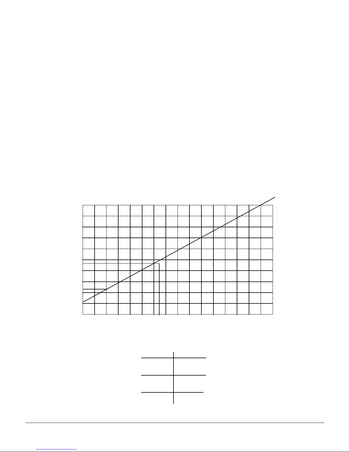
2.5
2.0
1.5
1.0
0.5
0.0
0.0 8.07.06.05.04.03.02.01.0
Blanked Dimensions or Minimum
Object Sensitivity in Inches
Penetration Factor D(pf) in Inches
DPF
1 inches
3.1 inches
8 inches
Detection
14mm
30mm
70mm
The minimum separation distance depends on the
application. Thefollowing formula shouldbeusedwhen
calculating this distance:
DS= K x (TS+ TR+ TC+ TBM) + DPF
where:
DS= Minimum separation distance between the
device and the nearest point of operation
hazard in inches.
K = Hand speed constant.
See note.
TS= Stop time of the machine tool measured at
the final control element.
TC= Response time of the control system.
NOTE: TSand TC are usually measured by
a stop-time measurement device.
TR= Response time of the presence-sensing device
and its interface, if any, as stated by the
manufacturer or as actually measured.
TBM = Additional time allowed for the brake monitor (if
used) to compensate for variations in normal
stopping time.
DPF = Added distance due to the penetration factor,
as recommended in the illustration below. The
minimum object sensitivity is stated by the
manufacturer. If beam blanking or floating
window features are used, these figures should
be added to the object sensitivity figure before
using the chart.
NOTE: The value of the hand speed constant, K, has
been determined by various studies.
Although these studies indicate speeds of 63
in/sec to over 100 in/sec, they are not
conclusive determinations. The employer
should consider all factors, including the
physical ability of the operator, when
determining the value of K to be used.
Table of contents
Other Tapeswitch Lighting Equipment manuals


