Ercolina Medi Bender User manual
C
CM
ML
L
I
In
nt
te
er
rn
na
at
ti
io
on
na
al
l
S
S.
.p
p.
.A
A.
.
Art.070 User Guide EN 1
I
In
ns
st
tr
ru
uc
ct
ti
io
on
n
M
Ma
an
nu
ua
al
l
M
Me
ed
di
i
B
Be
en
nd
de
er
r
A
Ar
rt
t.
.
0
07
70
0
M
Me
ed
di
i
B
Be
en
nd
de
er
r
S
Sp
pe
ec
ci
ia
al
l
A
Ar
rt
t.
.
0
07
71
1
User Guide EN
Rev. 1.0.0
Date 04.23.2004
Fields of use
MECHANICAL – HYDRAULIC – METAL FABRICATION – MARINE ENGINEERING
– ELECTRICAL GENERAL INSTALLATION
Ercolina®
by CML International S.p.A. ITALY
+39 0776 40281
¬+39 0776 40281
www.ercolina.it
CML U.S.A. Inc.
8506 North Fairmount
Davenport Iowa 52806 (USA)
+1 563 391 7700
¬+1 563 391 7710
www.ercolina-usa.com
CML DEUTSCHLAND GmbH
Grafenbergweg 11
73614 Schorndorf
+49 (0) 7181 87266
¬+49 (0) 7181 87298
www.ercolina.com
|cml-deutschland@t-online.de
CML France S.a.r.l.
La Gare
10190 Villemaur sur Vanne (F)
+33 325 4081 04
¬+33 325 4081 13
www.ercolina.com
|cmlfrance@wanadoo.fr

Distributed by:
Trick-Tools
75 Truman Road
Pella, IA 50219
Phone:1-877-VAN-SANT
E-mail: sales@trick-tools.com
Here at Trick Tools we believe that our customers deserve the best
value in their tool and equipment purchases. We are constantly at
work searching out a variety of high quality, high performance tools
to oer at the best prices possible. Our commitment to you is that
we will not oer “cheap junk” anywhere on our website. You, the
customer, help us to evaluate our products constantly and as soon as
an ongoing quality issue is uncovered we will correct it or disconnue
that product immediately. We hope to earn your connued trust.

C
CM
ML
L
I
In
nt
te
er
rn
na
at
ti
io
on
na
al
l
S
S.
.p
p.
.A
A.
.
Art.070 User Guide EN 2
Ercolina®Digital Medi Bender Art. 070
Electric Metal Bending Machine.
Ercolina®Digital Medi Bender “Special” Art. 071
Electric Metal Bending Machine.
CE 1995 (In conformity with Dir. EEC 392/89)
Manufacturer:
CML International S.p.A.
Località Annunziata
03030 Piedimonte S.G. (FR) Italy
Phone: +39 776 404572
Fax: +39 776 404801
The Manufacturer is not liable for any damages due to the use of not original Ercolina® tooling
Congratulations for the purchase of your Medi Bender. Observe the following instructions and your Medi
Bender will become a simple and useful working tool.
Note: this manual supplies the necessary instructions for the Digital Medi Bender (Art. 070), the Digital
Medi Bender Special (Art. 071). If not otherwise specifically indicated, these instructions are valid for the
three models.
Remember: read this manual and keep it in a safe place for future reference!
EC Conformity
The three Medi Bender versions are in conformity with Machine Directive EEC 392/89.

C
CM
ML
L
I
In
nt
te
er
rn
na
at
ti
io
on
na
al
l
S
S.
.p
p.
.A
A.
.
Art.070 User Guide EN 3
Contents
GENERAL RULES 5
1.1 GENERAL SAFETY RULES 5
1.1.1 TERMINOLOGY USED 6
1.1.2 GENERAL WARNINGS 7
1.1.3 GENERAL INSTRUCTIONS 8
1.1.4 TRANSPORTATION 9
1.2 NOTES ON THE OPERATION 9
TECHNICAL DATA 10
2.1 PART IDENTIFICATION 10
2.1.1 FORMER 11
2.1.2 COUNTERBENDING DIE 11
2.1.3 SLIDER – COUNTERBENDING DIE UNIT 12
2.2 TECHNICAL DATA 13
2.2.1 WORKING CAPACITY 13
2.2.2 MAXIMUM BENDING ANGLE 13
2.2.3 MACHINE CAPACITY 14
2.2.4 HEXAGONAL SHAFT SPEED 14
2.2.5 ELECTRICAL DATA 15
2.2.6 DIMENSIONS AND WEIGHT 15
2.2.7 NOISE LEVEL 15
2.2.8 TECHNICAL NOTES 15
MACHINE USE 16
3.1 MAIN CONCEPTS 16
3.2 ACCESSORIES 16
3.2.1 ACCESSORY CHOICE 16
3.2.2 ACCESSORY ASSEMBLY 16
3.2.3 MACHINE TURNING-ON 17
3.2.4 MACHINE PREPARATION 17
3.3 PROGRAMMING A BEND ON DIGITAL MODELS – ART. 070 AND 071 19
3.4 BENDING OPERATIONS WITH DIGITAL MODELS – ART. 070 AND 071 19
3.4.1 HOW TO REGAIN THE SPRING BACK ANGLE 19
3.5 EXAMPLES OF CORRECT BENDING WITH THE MEDI BENDER 21
3.6 MAINTENANCE 22
3.7 HOW TO FIT THE SPECIAL HEXAGONAL SHAFT 23
3.8 VICE ASSEMBLY (ACCESSORY) 24
3.9 SPACER FOR SPECIAL RADIUS 25
APPENDIXES 26
4.1 APPENDIX 1 26
4.2 APPENDIX 2 27
4.3 APPENDIX 3 28
4.4 APPENDIX 4 29

C
CM
ML
L
I
In
nt
te
er
rn
na
at
ti
io
on
na
al
l
S
S.
.p
p.
.A
A.
.
Art.070 User Guide EN 4
Tables
TABLE 2.1.1 – PART IDENTIFICATION 10
TABLE 2.2.1 – MACHINE CAPACITY 14
TABLE 2.2.2 – HEXAGONAL SHAFT SPEED 14
TABLE 2.2.3 – SUPPLY VOLTAGE 15
TABLE2.2.4 – PROTECTION FUSES 15
TABLE 2.2.5 – DIMENSIONS AND WEIGHT 15
TABLE 3.4.1 – SPRING BACK ANGLE SETTING 20
TABLE 3.7.2 – SPECIAL HEXAGONAL SHAFT 23
Figures
FIGURE 2.1.1 – FORMER 11
FIGURE 3.2.3 – BRACKET UNIT 18
C
CM
ML
L
I
In
nt
te
er
rn
na
at
ti
io
on
na
al
l
S
S.
.p
p.
.A
A.
.
Art.070 User Guide EN 5
SECTION I
GENERAL RULES
1.1 GENERAL SAFETY RULES
Pay attention to this symbol; it indicates a possible dangerous situation
Pay attention to this symbol; it indicates a forbidden action for the Operator/User
Pay attention to this symbol; it indicates a mandatory action for the Operator/User
MANDATORY
Read carefully the USE AND MAINTENANCE MANUAL before using the machine
WARNING
The Manufacturing Company is not liable for any accident, damage or machine malfunction due to non-
observance of instructions included in the machine USE AND MAINTENANCE MANUAL, section II: safety and
prevention, or to safety device tampering.

C
CM
ML
L
I
In
nt
te
er
rn
na
at
ti
io
on
na
al
l
S
S.
.p
p.
.A
A.
.
Art.070 User Guide EN 6
1.1.1 TERMINOLOGY USED
Some recurrent definitions are explained below:
USER THE PERSON OR BODY OR COMPANY THAT HAS BOUGHT OR RENTED THE
MACHINE AND THAT INTENDS TO USE IT ACCORDING TO ITS EXPECTED USE
AND SCOPE; MACHINE USE AND OPERATING PERSONNEL TRAINING IS HIS/HER
RESPONSIBILITY.
DANGEROUS AREA ANY AREA INSIDE AND/OR NEAR TO A MACHINE WHERE THE PRESENCE OF AN
EXPOSED PERSON, CONSTITUTES A SAFETY AND/OR HEALTH RISK FOR THE
PERSON HIMSELF/HERSELF.
EXPOSED PERSON ANY PERSON THAT IS ENTIRELY OR PARTIALLY WITHIN THE DANGEROUS ZONE.
OPERATOR PERSON IN CHARGE OF INSTALLING, OPERATING, REGULATING,
MAINTAINING, CLEANING, HANDLING OR DEMOLISHING THE MACHINE.
HE/SHE IS NOT AUTHORIZED/ENABLED TO PERFORM ELECTRICAL
INTERVENTIONS WITH VOLTAGE SUPPLIED.
QUALIFIED PERSONNEL PERSONS THAT HAVE BEEN SPECIFICALLY TRAINED AND ENABLED TO
PERFORM MAINTENANCE OR REPAIRING OPERATIONS THAT REQUIRE A
PARTICULAR MACHINE OPERATING, SAFETY AND INTERVENTION MODALITY
KNOWLEDGE AND THAT ARE ABLE TO RECOGNIZE DANGERS CAUSED BY
MACHINE USE AND TO CONSEQUENTLY AVOID THEM.
AUTHORIZED
SERVICE CENTER BODY THAT HAS BEEN LEGALLY RECOGNIZED BY THE MANUFACTURING
COMPANY AND THAT HAS QUALIFIED AND AUTHORIZED PERSONNEL TO
PERFORM ALL SIMPLE OR COMPLEX SERVICE, MAINTENANCE AND REPAIRING
OPERATIONS THAT ARE NECESSARY TO KEEP THE MACHINE IN PERFECT
EFFICIENCY CONDITIONS.

C
CM
ML
L
I
In
nt
te
er
rn
na
at
ti
io
on
na
al
l
S
S.
.p
p.
.A
A.
.
Art.070 User Guide EN 7
1.1.2 GENERAL WARNINGS
Read Carefully the MACHINE USE AND MAINTENANCE MANUAL before using the machine;
The User must only assign the machine to specifically trained and qualified personnel;
The User must take all the necessary measures to prevent unauthorized personnel from accessing the
machine;
The User must suitably inform the personnel on safety rules observance and application; for this scope
he/she must guarantee that anybody, according to his/her own responsibilities, knows machine use
instructions and the relevant safety instructions;
The User must inform the Manufacturing Company if he/she finds any safety device defect or
malfunction, as well as any potentially dangerous situation;
The Operator must always use the DPI Individual Protection Devices (gloves, safety shoes and specific
clothes) and must observe the instructions of this manual;
The Operator must observe all danger, warning and caution instructions indicated on the machine;
The Operator must not perform any operation or intervention that does not lie within his/her
competence;
The Operator must inform his/her own Supervisor on every problem or dangerous situation that may
arise;
The User must not allow that parts of other brands are assembled on the machine, since testing has
been performed with parts included in the machine at the time of the supply of the machine and this or
other changes may vary its characteristics and compromise operating safety; any accessory
modification and/or addition must be specifically approved and/or made by the Manufacturer;
The machine must only be used observing the purposes of use it was designed for;
During operation you may find: live electrical parts, mechanical parts in motion. So do not remove any
guard and do not loose screws or fastenings since serious damage can be caused to things or persons.

C
CM
ML
L
I
In
nt
te
er
rn
na
at
ti
io
on
na
al
l
S
S.
.p
p.
.A
A.
.
Art.070 User Guide EN 8
1.1.3 GENERAL INSTRUCTIONS
The MEDI BENDER machine has been manufactured according to the most modern technology and
observing the officially recognized safety rules. However, the machine may be source of risk for the user
and/or third persons if improperly or incorrectly used. For this reason, it is fundamental to read and apply
the following safety rules:
The machine must be exclusively used as intended by design and observing general safety and risk
prevention rules. The Manufacturer is not liable for damages to things or persons due to an improper
machine use;
Check that power supply observes the necessary voltage for the Medi Bender;
Only assign qualified personnel to the machine;
Do not use the machine in environments containing inflammable gas or fluids;
Do not expose the machine to rain;
Keep the machine in a safe and dry place;
Keep unassigned personnel at a safety distance during machine work and stop phases;
Do not touch parts in motion;
Keep a safety distance when the machine is operating;
Do not ever stay near the machine at the machine control panel’s opposite side;
Avoid accidental starting-up;
For safety reasons and to keep warranty validity, do not tamper with electronic and disk circuits;
Unplug machine from power supply before transportation;
Do not ever handle the machine pulling the supply cable;
Do not modify the machine structure.
Only use Ercolina® accessories. Machine tampering implies warranty invalidation. The Manufacturer
may not supply accessories or spare parts if the machine has been tampered with;
Hold the heaviest formers from the groove when applying them to avoid finger crushing;
C
CM
ML
L
I
In
nt
te
er
rn
na
at
ti
io
on
na
al
l
S
S.
.p
p.
.A
A.
.
Art.070 User Guide EN 9
Check periodically the hexagon wearing;
Only one person at a time must use the machine.
1.1.4 TRANSPORTATION
WARNING
BEFORE TRANSPORTING THE MACHINE :
♦Unplug power supply;
♦Disconnect the pedal switch;
♦Remove all the accessories assembled on the machine.
WARNING
DURING MACHINE TRANSPORTATION:
♦Pay attention to the machine weight: 23 Kg;
♦Use the handle;
1.2 NOTES ON THE OPERATION
During the first 15/20 bends the machine is in a running-in phase, so it could not be able to bend tubes of
maximum capacity. After the running-in phase, the machine may be used for all tubes included in the table.
C
CM
ML
L
I
In
nt
te
er
rn
na
at
ti
io
on
na
al
l
S
S.
.p
p.
.A
A.
.
Art.070 User Guide EN 10
SECTION II
TECHNICAL DATA
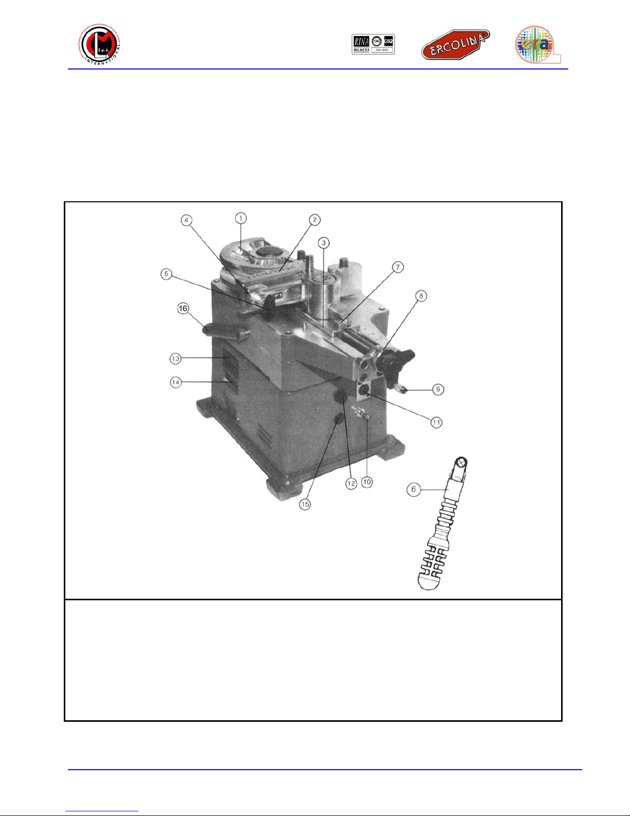
2.1 PART IDENTIFICATION
1Former 9Knob
2Counterbending die 10 Switch
3Swivelling bracket 11 Foot switch connection
4Counterbending die support 12 Fuse holder
5Tightening screw 13 Degree selector
6Lever 14 Display
7Stop 15 Overload led
8Reset ring 16 Handle
Table 2.1.1 – Part identification
C
CM
ML
L
I
In
nt
te
er
rn
na
at
ti
io
on
na
al
l
S
S.
.p
p.
.A
A.
.
Art.070 User Guide EN 11
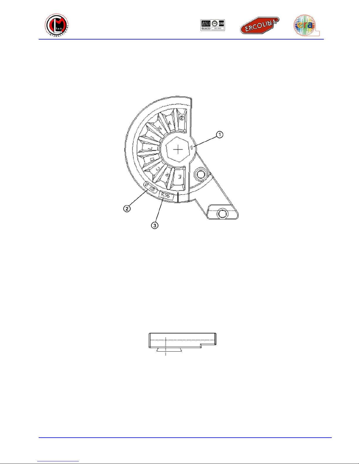
2.1.1 FORMER
The information included in the former is:
Figure 2.1.1 – Former
1Point of reference “0” for placing the former
2Tube diameter for which the former has been designed
3Former bending radius
2.1.2 COUNTERBENDING DIE
The information stamped on the counterbending die is regarding the tube dimensions it was designed for.
C
CM
ML
L
I
In
nt
te
er
rn
na
at
ti
io
on
na
al
l
S
S.
.p
p.
.A
A.
.
Art.070 User Guide EN 12
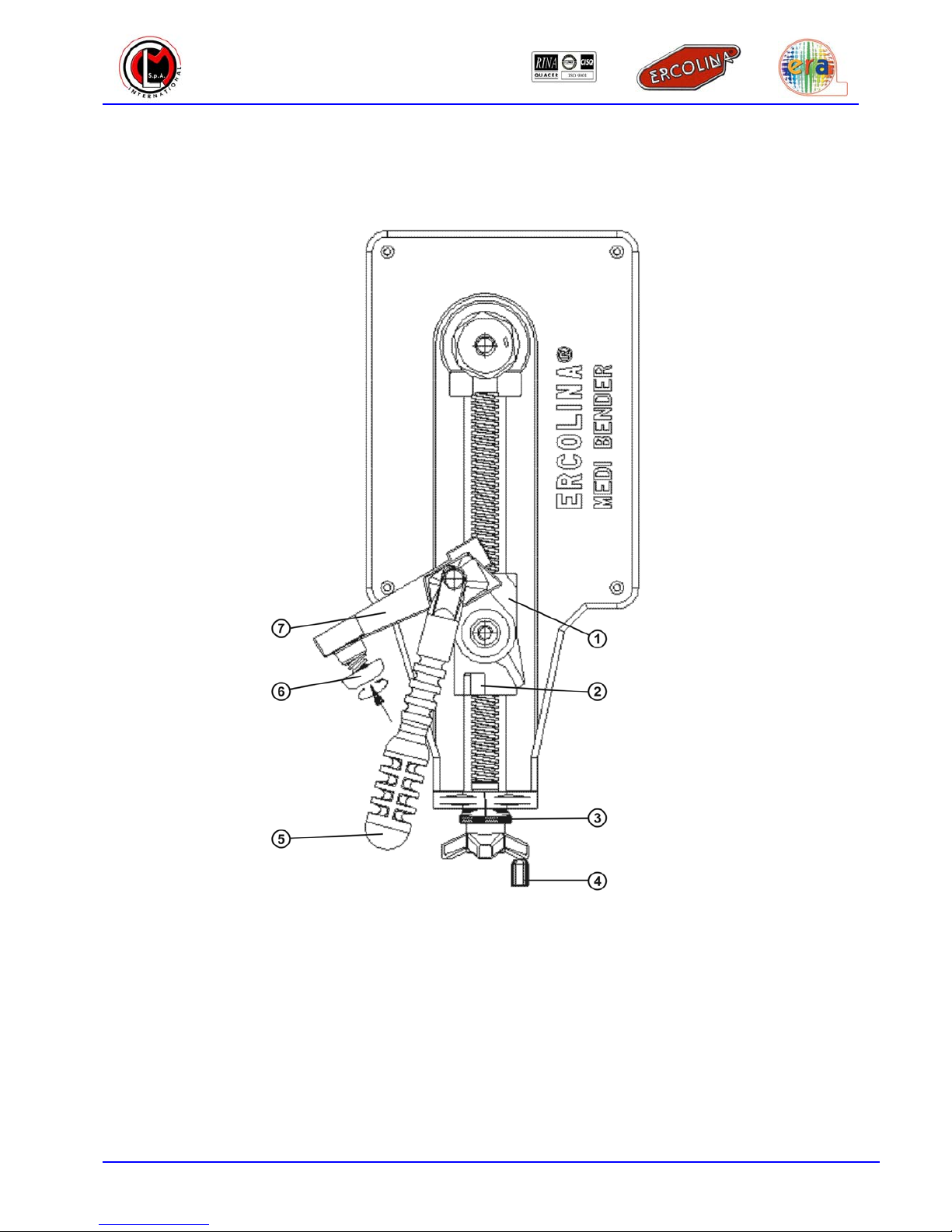
2.1.3 SLIDER – COUNTERBENDING DIE UNIT
Slider-counterbending die unit elements are indicated in the following figure:
1Swivelling bracket
2Stop
3Reset ring
4Knob
5Lever
6Counterbending die tightening screw
7Counterbending die support

C
CM
ML
L
I
In
nt
te
er
rn
na
at
ti
io
on
na
al
l
S
S.
.p
p.
.A
A.
.
Art.070 User Guide EN 13
2.2 TECHNICAL DATA
The following data refers to machines:
♦Digital Medi Bender Art. 070;
♦Digital Medi Bender Special Art. 071.
2.2.1 WORKING CAPACITY
The machine can bend materials included in the table starting from a minimum diameter of 5 mm, with
minimum radius depending on material used, diameter and thickness.
Note: The machine can only bend material types included in the table. The same table indicates
maximum capacities.
2.2.2 MAXIMUM BENDING ANGLE
The machine is equipped with an electronic system that manages bending operations in an accurate and
precise way, saving the set bending angle.
The maximum allowed bending angle on the machine is 180°.

C
CM
ML
L
I
In
nt
te
er
rn
na
at
ti
io
on
na
al
l
S
S.
.p
p.
.A
A.
.
Art.070 User Guide EN 14
2.2.3 MACHINE CAPACITY
The following table indicates the maximum bending capacity of the Digital Medi Bender Art. 070 and of
the Digital Medi Bender Special Art. 071.
The information reported below is approximate and may vary according to the material chemical
composition.
MAXIMUM BENDING CAPACITY WITH MINIMUM RADIUS EQUAL TO TWICE THE TUBE Ø
MEDI BENDER ART.070 MEDI BENDER ART.071
SECT MATERIALS Ø MAX x THICKNESS
(mm)
Ø MAX x THICKNESS
(inches OD)
Ø MAX x THICKNESS
(mm)
Ø MAX x THICKNESS
(inches OD)
Boiler tube 34 x 3 1” gas x 1/8” 22 x 3 1/2 ” gas x 1/8”
Mild steel tube 35 x 2,5 1” 3/16 x 7/64” 25 x 2,5 1” x 7/64”
Soft brass tube 32 x 3 1” 1/4x 1/8” 28 x 3 1” 3/8x 1/8”
Stainless steel 35 x 1,5 1” 3/8x 1/16” 28 x 1,5 1” 1/8 x 1/16”
Welded furniture tubing 32 x 1,5 1” 1/4x 1/16” 28 x 1,5 1” 1/8 x 1/16”
St35 hydraulic steel tube 35 x 3 1” 3/8x 1/8” 28 x 1,5 1” 1/8 x 1/16”
Stainless steel hydraulic tube 35 x 2 1” 3/8 x 5/64” 28 x 1,5 1” 1/8 x 1/16”
Hard copper and aluminum 42 x 1,5 1” 5/8 x 1/16” 28 x 3 1” 1/8 x 1/8”
Mild steel solid round profile 20 3/
4
”16 5/
8
”
Mild steel solid flat profile 10 x 25 3/8” x 1” ---- ----
Mild steel rectangular profile 15 x 25 x 3 5/8” x 1” x 1/8” ---- ----
Mild steel solid square profile 20 x 20 3/4” x 3/4” ---- ----
Mild steel hollow square
profile 25 x 25 x 3 1” x 1” x 1/8” ---- ----
Mild steel T profile 30 x 30 x 5 1” 3/16 x 1” 3/16 x 3/16” ---- ----
Mild steel U profile 30 x 15 x 5 1” 3/16 x 1” 5/8x 3/16” ---- ----
Table 2.2.1 – Machine Capacity
2.2.4 HEXAGONAL SHAFT SPEED
The hexagonal shaft speed of the Digital Medi Bender machine is:
Machine Hexagonal Shaft Speed
Digital Medi Bender Art. 070 2.9 rpm
Digital Medi Bender Special Art. 071 9.0 rpm
Table 2.2.2 – Hexagonal Shaft Speed

C
CM
ML
L
I
In
nt
te
er
rn
na
at
ti
io
on
na
al
l
S
S.
.p
p.
.A
A.
.
Art.070 User Guide EN 15
2.2.5 ELECTRICAL DATA
Machines must be connected to the power supply it was intended for by design.
Power supply:
Voltage Frequency Power Current
220V 50/60Hz 1000W 5A
110V 50/60Hz 1000W 10A
Table 2.2.3 – Supply Voltage
Insulation level: 1
Motor: electrical motor with double insulation in conformity with EC standards
Protection: protection system with fuses
Model Fuse
Voltage General Protection Electronic Circuit
220V 8A gG 315mA gG
110V 16A gG 630mA gG
Table2.2.4 – Protection Fuses
Motor overloading protection: automatic electronic blocking at 1000W on all models
2.2.6 DIMENSIONS AND WEIGHT
Machine body:
Machine body
Machine body without accessories 23Kg
Width 260mm
Length 600mm
Height 900mm
Table 2.2.5 – Dimensions and Weight
Maximum usable former weight: 10Kg
2.2.7 NOISE LEVEL
Emission values on working areas: 82dB(A)
EC DIR. 392/89 – I, 1, 7, 4, F
2.2.8 TECHNICAL NOTES
Machine design and technical specifications may be modified without advice.

C
CM
ML
L
I
In
nt
te
er
rn
na
at
ti
io
on
na
al
l
S
S.
.p
p.
.A
A.
.
Art.070 User Guide EN 16
SECTION III
MACHINE USE
3.1 MAIN CONCEPTS
Bending angle: Tube bending angle expressed in degrees
Spring back angle: Due to the material elasticity effect the tube tends to “spring back” to its original
shape when it is bent
Bending radius: It must not be confused with the angle, it is measured from the tube center to the
bending center
The Ercolina system is able to correct the bending angle according to the material used
3.2 ACCESSORIES
Formers and counterbending dies are made of aluminum and steel according to the material to bend. Ask
your dealer.
For part identification refer to Table 2.1.1 included on page 10.
3.2.1 ACCESSORY CHOICE
Choose the correct former and counterbending die to bend your tube. Verify that the external diameter is
exactly equal to the one stamped on the former and on the counterbending die.
3.2.2 ACCESSORY ASSEMBLY
Insert former and counterbending die on their respective positions.
Pay attention when installing steel formers: hold the formers from their edge side and NOT from the
bottom. Make sure the former point of reference is aligned with the hexagonal shaft point of reference and
fix the counterbending die to the support by rotating the small knob.

C
CM
ML
L
I
In
nt
te
er
rn
na
at
ti
io
on
na
al
l
S
S.
.p
p.
.A
A.
.
Art.070 User Guide EN 17
3.2.3 MACHINE TURNING-ON
The machine turns on as soon as it is connected to a power supply (220 V or 110 V).
Warning: Check that power supply voltage observes the machine design voltage before plugging it to
the power supply.
3.2.4 MACHINE PREPARATION
Insert the tube and prepare the swivelling bracket.
Tightly close the tube between the former and the counterbending die using the knob. Align locknut and
machine movements without rotating the knob. The indicated position constitutes a point of reference for
adjusting clamping.

C
CM
ML
L
I
In
nt
te
er
rn
na
at
ti
io
on
na
al
l
S
S.
.p
p.
.A
A.
.
Art.070 User Guide EN 18
Figure 3.2.3 – Bracket Unit
1Counterbending die insertion handle Note: Press and rotate rightwards to hold.
Rotate leftwards to losen counterbending die.
2Attaching handle for slider set Note: Use the brass knob to speed up the approach
3Reset ring

C
CM
ML
L
I
In
nt
te
er
rn
na
at
ti
io
on
na
al
l
S
S.
.p
p.
.A
A.
.
Art.070 User Guide EN 19
3.3 PROGRAMMING A BEND ON DIGITAL MODELS – ART. 070 AND 071
NOTE. Only for Digital Medi Bender Art. 070 and 071.
Make sure that the hexagonal shaft and the assembled former are set to the reference point. Program the
desired angle by setting the central degree setting unit. Once this is done, the machine is ready to perform
an angle. If material elasticity is known, also the spring back angle can be programmed on the first two
degree selectors. If such value is not known it will be saved later.
1Bending angle selector
2Spring back angle selector
3.4 BENDING OPERATIONS WITH DIGITAL MODELS – ART. 070 AND 071
NOTE. Only for Digital Medi Bender models Art. 070 and 071.
The machine is now ready to bend. To bend observe the following instructions:
a. Press the switch rightwards [Bend] or press the pedal [Bend]. The former will rotate and the tube
will be bent to the angle value. As soon as the bending will be completed the machine will
automatically stop and the display will show the bending angle value and the spring back angle
value (selected values will be kept in memory even if the machine is turned off).
b. Press the bend/return switch leftwards [Return] or press the foot switch pedal[Return] and the
former will rotate on the other sense returning to the point of reference position, allowing to remove
the bent tube.
3.4.1 HOW TO REGAIN THE SPRING BACK ANGLE
Observe the following procedure if the spring back angle has not been selected:
a. Push the bend/return switch rightwards [Bend] by inpulses, or press the pedal [Bend] by impulses
until the tube visibly starts to bend.
b. Stop the bending process and read the angle value shown in the display.
c. Select the value read on the first two selectors, this is the spring back angle.
This manual suits for next models
1
Table of contents


