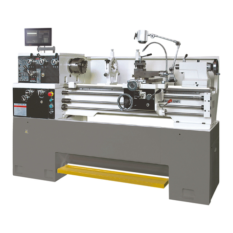
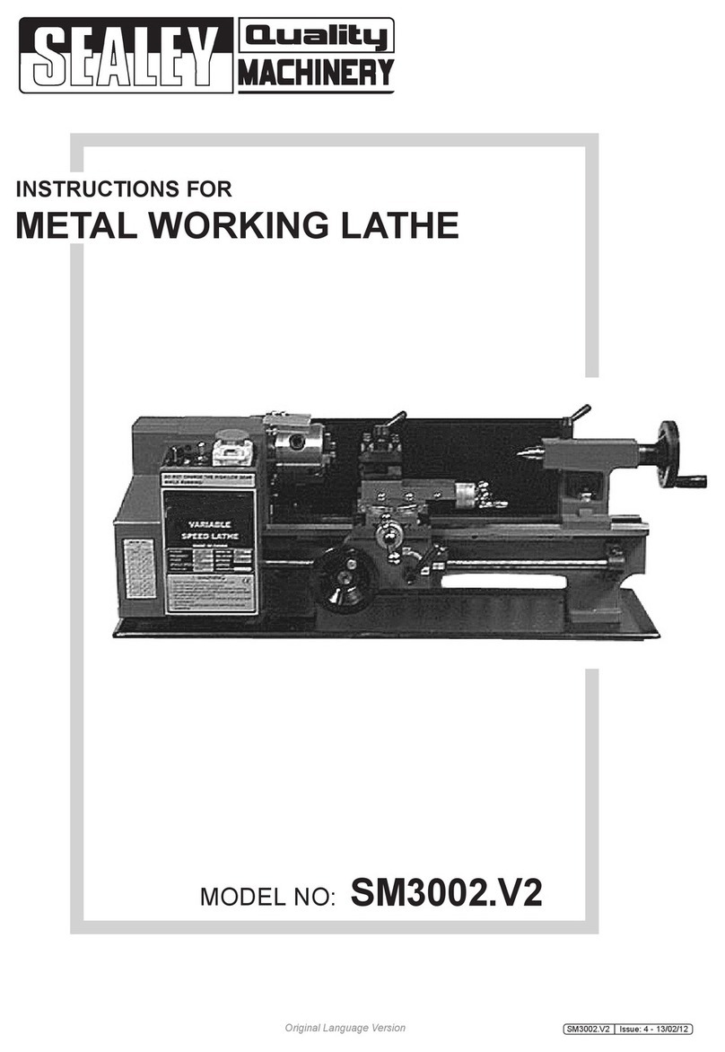
CHESTER Crusader User manual

Contents
1. Machine Specifications
2. Electrical System
3. Installation
4. Levelling
5. Lubrication Chart
6. Operation Instruments
7. Protection Instruments
8. Troubleshooting
9. Maintenance
10. Parts List and Diagrams

1. Machine Specification
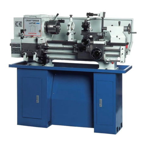
The Crusader Lathe has been designed for small to medium sized workpieces and
suitable for use in machining workshops, tool rooms, and repair workshops to machine
shafts, sleeves and disc shaped workpieces. This machine can also be used to cut
imperial, diametric and module pitch threads. The machine is easy and reliable to
operate, easy to repair, offers high efficiency and low noise levels. The sliding
surfaces of the bed have been hardened using a supersonic frequency heat-treatment
method, this allows the sliding surfaces wear resistance.
Overall Measurements
Technical Data
Swing over bed
300mm
Swing over gap
440mm
Swing over saddle
173mm
Distance between centres
900mm
Length of bed
1473mm
Width of bed
185mm
Hole through spindle
38mm
Tailstock quill travel
100mm
Cross slide travel
130mm
Tool slide travel
85mm
Carriage travel
850mm
Spindle Taper
MT5
Tailstock Taper
MT3
Spindle speed range
18 Steps; 67-1800rpm
Leadscrew diameter
22mm
Feed rod diameter
19mm
Leadscrew thread pitch
8TPI (Imperial); 3mm (Metric)
Threads that can be cut
Imperial
34 kinds; 4-56TPI
Metric
26 kinds; 0.4-7mm
Motor power
1.5kW (2hp)
Net weight with/without stand
450Kg
Noise level
<83dB

2. Electrical System
This machine has been wired as either a 230V Single Phase machine or a 415V 50hz
3 Phase machine.
The electrical system in the lathe has been installed and adjusted prior to delivery, as
such it should not normally be necessary to open the electrical box. Connect the
machine to the power supply making sure that the ground has been correctly wired. If
this is a three-phase machine, turn the machine on and start the spindle to check that
it is turning in the correct direction, if the direction is incorrect, turn off the machine and
swap any two of the wires into the machine and then recheck.
Caution!
If there is a need to carry out any maintenance or repair work on the electrical system
of this machine, only a qualified electrician should be allowed to carry out such works.
Make sure any electrical works are carried out as per the electrical drawings.
2.1 Electrical Drawings
Three Phase

Single Phase

2.2 Wire Chart
Three Phase

Single Phase

2.3 Description
Symbol
Name
Symbol
Name
M
Motor
SB2
Jog Switch
TC
Transformer
SQ3
End Gear Train Cover Limit
Switch
HL
Indicator Light
SQ4
Chuck Guard Limit Switch
EL
Work Light
SQ5
Brake Switch
SB1
Stop Switch
FR
Thermal Relay
SB3
Emergency Stop Button
3. Installation
Caution!
The machine must be securely and stably fitted. Do not turn, lower or make any sharp
movements through shaking, wind force, or any other external movements.
3.1 Foundation
The base that this machine is to be installed on must be solid and heavy enough to
support the weight and must be level.
A concrete floor is the best foundation, it provides a rigid base and helps minimise the
vibration from any other machines.
When determining the position of the installation, leave a certain distance around the
machine in accordance to the overall dimensions and installation dimensions of the
machine to allow the machine to be easily operated and repaired.
When installing the stand, mark and drill eight holes in the base as per the foundation
plan, see below, then place the foundation bolts into the holes. Place the stands on
to the base and place the two adjustable iron spaces at the front and back of each
stand. Secure the connecting block for the left and right stands then secure the stand
to the base, then lift the lathe onto the stand, securing it in place using the bolts and
nuts.
3.2 Lifting the Machine
The lathe should be lifted as per the following diagram:
Place soft material between the surface of the machine and the lifting ropes/straps to
avoid damaging the machines surfaces.
The machine weighs in total approximately 390Kg (330Kg for the machine and 60Kg
for the stand), keep the machine balanced when lifting to avoid tilting the machine in

any direction.
The carriage, tailstock and other sliding parts of the lathe are locked before delivery,
do not loosen these until the machine is installed in its final location. Before lifting the
machine, confirm that these items are fully locked down to prevent causing an accident
in the event they are not locked and move. Carefully lower the lathe on to the
foundation to prevent causing any damage to the machine.
3.3 Cleaning
This machine has been coated with a layer of anti-rust oil to all of the bare metal
surfaces to prevent rusting. Before moving the carriage or the tailstock, use a cleaning
solvent to remove the oil making sure that all of the anti-rust oil is removed. Apply a
thin layer of oil to the machines bare metal surfaces to protect them from rust.
4. Levelling
To ensure the continued accuracy of the machine, the machine must be kept level at
all times. To level the machine, use the following procedure:
A. Longitudinal Level
Once the guideways have been cleaned thoroughly, loosen the nuts holding the
machine to the foundation and place a 150mm precision machinists level onto the
cross slide in the longitudinal direction and move the carriage along the full length of
the travel, adjust the level of the machine by adjusting the adjustable spacers and
recheck the reading on the level. Continue this process until the machine is fully level
along the full length of the machine bed.
B. Cross Level
Place the spirit level onto the cross slide in the cross direction (across the bed) and
move the carriage along the guideways in the longitudinal direction towards the
headstock, take a reading and then move the carriage towards the tailstock. The
reading at this end must match the reading from the tailstock, there must not be
allowed to be any twist in the bed. If the reading is different, adjust the levelling
wedges until the bed is level.

Any adjustments at one end of the bed will affect the reading at the other end, the
levelling procedure may need to be repeated several times until the bed is level along
the length of the guideway. Once any adjustments are complete, carefully tighten the
foundation screws, the tension should not change the level of the machine, re-check
the levels and make minor adjustments if necessary.
After the machine has been in operation for a period of time, check the levels to make
sure that the accuracy of the machine is maintained. Make any adjustments as
mentioned above if necessary. Periodic level checks should be part of a routine
maintenance schedule.
5. Lubrication Chart
Add oil up to the indicator mark in the oil window.
Lubricate at the start of each shift
Check the lubrication at the start of each shift
Caution!
Lubrication of the machine is extremely important to ensure the continued operation
of the lathe. Make sure to only lubricate with the correct amount of oil, if there is
insufficient lubrication, it could affect the accuracy of the lathe and increase the rate of
wear on the slideways. Adding too much lubricant will be a waste of oil and will lead
to a dirty workspace. Too much oil could cause a leak through the top of the headstock
due to the movement of the gears in the headstock.

9. Operation Instructions
1. Speed Levers and Feed Direction Lever; 2. Headstock Cover; 3. Headstock; 4.
Three Jaw Chuck; 5. Gap; 6. Steady Rest; 7. Follow Rest; 8. Tool Post Handle; 9. Tool
Post Slide; 10. Tailstock Quill Clamping Lever; 11. Tailstock; 12. Tailstock Clamping
Lever; 13. Adjusting Screw; 14. Three Rod Support Seat; 15. Chip pan; 16. Control
Lever; 17. Threading Dial; 18. Half Nut Lever; 19. Cross/Longitudinal Feed Lever; 20.
Apron; 21. Longitudinal Feed Handwheel; 22. Carriage; 23. Control Rod; 24. Feed
Rod. 25. Leadscrew; 26. Rack; 27. Limit Switch Box; 28. Oil Level Gauge; 29. Change
Gear Handle; 30. Pulley Cover; 31. Power Switch; 32. Emergency Stop Button; 33.
Start Switch; 34. Indicator Light
Caution!
• Do not operate the lathe before you have thoroughly read the operation manual
and fully understand all of the controls and functions on the lathe. Before starting
to cut a workpiece, make a trial cut to help you familiarize yourself with the
functions of the machine.
• Before operating the machine, check the oil levels and the lubrication of all of the
sliding and rotating parts, if there is not enough lubrication, check the lubrication
chart and lubricate the machine as per the chart.
• The lathe has been provided with a lamp, however, the operator should provide
adequate lighting to remove any shadows from the work area to prevent any
accidents due to poor light conditions.
• Make sure that the workpiece is clamped correctly to prevent it from flying off. The
protruding workpiece should not be too long to help maintain the working precision.
• In the event of an emergency when turning, press the emergency stop button or
press the foot brake to stop the machine immediately. Make sure any issues are
resolved before putting the machine back into operation.
• Cutting Depth Selection: When choosing the cut depth, take into consideration the

limitations of the lathe, the tool and the rigidity of the workpiece. Do not overload
the machine by taking too large a cut. As a guide, the following chart gives an idea
on the cutting speed, depth and feed rate when cutting metals, when cutting wood,
plastic and other non-metals, the cut depth can be increased.
Workpiece
Diameter
Cut Speed
Cut Depth
Feed Amount
≥150
<160rpm
<0.5mm
<0.1mm/RPM
≥100-150
<200rpm
<0.5mm
<0.1mm/RPM
≥50-100
<400rpm
<1mm
<0.15mm/RPM
≥30-50
<1000rpm
<1.5mm
<0.15mm/RPM
<30
<1300rpm
<1mm
<0.1mm/RPM
Note:
When the rate of the outstanding length and diameter of the workpiece is over
100mm, the cut depth and feed rate should be reduced.
• Once the operation is complete, turn off the power and clean the lathe.
• When the machine requires maintenance or repairs, disconnect the lathe from the
power supply and place a sign on the machine stating it is under
repair/maintenance.
9.1 Headstock
The main spindle is driven by gears, three sets of sliding gears have been installed,
the position of which can be changed by operating lever 1. The machine has been
equipped with a belt from the motor to the spindle pulley, the tension of the belt has
been adjusted to the correct tension before the lathe was shipped, we would advise
checking the tension of the belt before starting the machine. When correctly tensioned,
the belt should depress by approximately ½” when pressed under normal finger
pressure, too tight and the belt could damage the bearings, too lose could lead to
premature wear and slipping. When it is necessary to adjust the belt tension, you will
need to adjust the bolt under the motor bracket to move the motor to the correct
position. The oil in the headstock should be changed regularly, the first change should
occur approximately 15 days after delivery, the second 45 days later then every 6-12
months depending on the amount of use the machine is subject to and the condition
of the oil. There is a drain hole under the headstock which has a screw to block the
oil, remove the screw to allow the oil to drain from the headstock, once the oil has
drained, clean the inside of the headstock with kerosene or other cleaning solvent then
fill the headstock with clean oil until the oil level reached the mid-point of the oil sight
glass.
Caution!
The oil level must be kept topped up, if the level of oil in the headstock is below the
middle of the oil sight glass, add oil to the machine until the correct level is reached.

9.2 Spindle Speed
The main spindle is capable of 18 speed steps which can be achieved by changing
the lever position, the speed can be adjusted as follows:
1. Move the control lever to the middle position to turn off the main motor.
2. According to the speed chart, the belt should be moved to either groove I or II (high
or low speeds)
3. Move the two levers A and B and make the arrow head point at the line for ABC or
123 as shown on the speed lever for the desired speed. If moving the lever is
difficult, rotate the chuck by hand to make sure that the gear engages.
Caution!
Do not change the spindle speeds whilst the spindle is running!
9.4 Main Spindle Rotation
Starting, stopping, forward and reverse of the spindle can be achieved by using the
control lever, when using the control pull it away from the headstock and then move
the lever either up (reverse) or down (forward).

When the control lever is in the middle position, the machine will stop.
9.5 Gearbox
Note: To avoid the rotation of the leadscrew, the handle must point to the black dot
when feeding.
Thread cutting can be completed by operating all four handles as per the thread chart
and operating the thread cutting engagement lever down. It should be engaged with
the leadscrew in order to obtain the longitudinal travel of the carriage, this is the thread
cutting feed.
The direction of thread cutting is controlled by the feed direction selector at the
headstock, the thread pitch can be selected by the position of the 4 handles.
Feed Table
a) Longitudinal and Cross Feed Table, Imperial Leadscrew

b) Longitudinal and Cross Feed Table, Metric Leadscrew

Thread Table
a) Thread Table, Imperial Leadscrew

b) Thread Table, Metric Leadscrew

9.6 Carriage
The function of the carriage is to securely support the tool post and carry it when
moving in both the longitudinal and cross directions.
1. Power Feed
When performing external turning and facing
operations, turn the lever to the black dot on the gear
box to engage the feed rod. To engage the power
feed in the longitudinal direction, pull the feed lever (A)
up, to engage the cross feed push the lever (A) down.
When the cross/longitudinal feed lever is engaged, the
half nut engagement lever (B) cannot be engaged, a
built-in safety interlock mechanism prevents the
simultaneous engagement of both levers.
When threading, place the levers on the gearbox to the required settings to engage
the leadscrew, the half nut lever (B) should then be engaged, this engages the half
nut with the leadscrew which in turn moves the carriage along the length of the bed.
Caution!
Do not force the half nut lever when engaging with the leadscrew.
2. Threading Dial
When threading a workpiece, the thread dial can be used and is located on the right-
hand side of the apron.
Using the thread dial indicator will allow the operator to correctly engage the leadscrew
so that the same groove will be cut on every pass, the dial is marked with line
numbered 1, 2, 3 and 4, in between each number are lines without numbers, these
are called un-numbered lines. When the dial is engaged with the leadscrew, the dial
will rotate, a single line is marked on the housing (fixed line), this is used to correctly
engage the half nut.
A plate is riveted to the front of the thread dial indicator which shows the selection and
sequence to match the rotating dial with the fixed line.
To start thread cutting, engage the half nut at the appropriate number as indicated on
the scale column on the thread dial plate, 1-4 on the scale means that the half nut can
be engaged on any of the numbered lines, for each successive cut only the numbered
lines can be used. 1-3/2-4 on the scale means that the half nut can only be engaged
on 1 and 3 or 2 and 4, for example, if you engage the half nut on number 1, then any

successive cuts must be made on number 1 or 3. 1-8 means
that the half nut can be engaged on any line.
If the half nut is left engaged when cutting the thread then the
dial indicator does not need to be used, in this case once
each cut has been completed, stop the machine, back the
tool off and reverse the spindle back to the start position. This
process can then be repeated until the thread has been full
cut.
9.7 Four-Way Tool Post
The main function of the tool post is to secure the cutting tool, the tool thickness must
be less than the grove in the tool post. When installing a tool, make sure to confirm
the height of the tool to the centre line of the rotating workpiece, use a spacer to adjust
the height of the tool before securing it in place. If the tool post needs to be turned,
turn the tool post locking handle counter-clockwise to loosen the locking handle, the
tool post can then be turned to the desired angle. Lock the tool post by turning the
handle clockwise.
9.8 Compound Slide
By using the compound slide, tasks such as taper cutting can be completed. Loosen
the screws on the saddle and then rotate the compound slide to the required angle
using the graduated dial on the side and lock the screws. A taper can then be cut
using the handwheel on the end of the compound slide.
9.9 Tailstock
The tailstock has been installed on top of the lathe bed and can be moved along the
guideways and locked by using the clamping lever (4). The tailstock quill has been
fitted with an end pin to prevent it from being fully extracted. Rotating the handwheel
(5) will extend or retract the quill, the handle (3) can then be used to lock the tailstock
quill in position (for example, when using a live centre). The tailstock has been
adjusted to match the centre line of the spindle
before it has been shipped, if you wish to use the
tailstock for taper turning, make sure that the
clamp lever is in the released position and adjust
the set screw to alter the centre of the tailstock
in comparison to the spindle. Once the desired
angle has been reached, clamp the tailstock in
position using the tailstock clamping lever.
Reposition the tailstock back into its original
position once the taper turning operation has

been completed.
When correcting the position of the tailstock, use the following procedure:
1. Fit a 305mm ground steel bar between the centres of the headstock and tailstock
(Fig 27).
2. Fit a dial indicator to the compound slide and feed along the centre line of the bar
using the carriage movement.
3. If the tailstock needs adjustment, loosen and tighten the front and rear hex socket
screws on the tailstock.
10. Troubleshooting
Caution!
Before performing any maintenance or carrying out any repairs, make sure that the
power supply to the lathe is disconnected.
1. Turn on the power, the spindle does not rotate.
A. The voltage is incorrect or the main switch has not been turned to on – Adjust the
voltage or turn the main power on at the source.
B. The fuse in the electrical box has blown – Check the fuse and replace if necessary.
C. A connection in the electrical cabinet is loose – Check the connections and make
sure that they are secure.
2. The motor is too hot or it is not producing the correct power.
A. The voltage is too low – adjust the voltage into the machine.
B. The motor is overloaded or been working for too long a time – reduce the load on
the motor.
C. The motor is damaged – replace the motor.
D. The fuse has tripped or the wire connection is poor – check the fuse and
connections and replace if necessary.
E. The belt is too tight – loosen the belt and adjust the belt to the correct tension.
3. The temperature of the spindle bearings is too high.
A. Not enough lubrication oil – fill the oil to the correct level.
B. The bearing assembly is too tight – Adjust the bearings until the spindle runs
smoothly.
C. High speed turning for long periods of time – reduce the cut depth.
4. Spindle does not move well when the motor is on.
A. The belt is too loose or is worn – Adjust the belt to the correct tension, replace if
necessary.
B. The motor is damaged – Replace the motor.
C. The fuse has blown – Replace the fuse.
Table of contents
Other CHESTER Lathe manuals
CHESTER
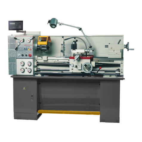
CHESTER Crusader Deluxe Lathe User manual
CHESTER
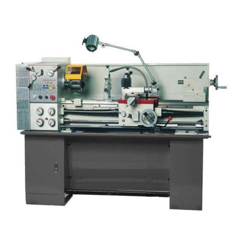
CHESTER Crusader VS User manual
CHESTER
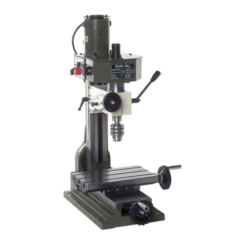
CHESTER Cobra Mill User manual
CHESTER
CHESTER Craftsman User manual

CHESTER
CHESTER DB8VS User manual

CHESTER
CHESTER CONQUEST SUPER LATHE User manual

CHESTER
CHESTER 920 User manual

CHESTER
CHESTER DB8VS User manual

CHESTER
CHESTER CONQUEST SUPER User manual

CHESTER
CHESTER DB10VS User manual

