PRASTEL FSLIMPRO Series User manual

FSLIMPRO05 - 10 - 15 - 20 - 25
FRANÇAIS
ISFSLIMPRO_10_12_fra.doc
1. GENERALITES
La barrière FSLIMPRO a été spécialement étudiée et réalisée pour permettre une installation facile et
rapide. L’électronique incorporée dans les profils et l'absence de signaux de synchronisation par câble
facilitent l'installation et réduisent au minimum la pose des câbles de liaison (uniquement l'alimentation et les
contacts d'alarme).
La disponibilité de profils de différentes tailles (1 à 2,5 m) permet d'adapter la protection selon les besoins
spécifiques. La fixation des profils par vis et joints toriques ainsi que la forme particulière des bouchons
garantissent l'étanchéité de la fixation et permettent de l'utiliser en extérieur.
Grâce à la forme du profil en aluminium et à la simplicité du système de fixation des sondes, il est possible
de les placer à l'intérieur de la barrière de sécurité FSLIMPRO, à la hauteur désirée, permettant de
l'optimiser selon vos propres exigences.
2. CARACTERISTIQUES PRINCIPALES
•Profil en aluminium
•Bouchon supérieur en caoutchouc et bouchon inférieur en ABS comportant un trou au fond, protégé par
une éponge permettant le passage de l'air, évitant la formation de buée à l'intérieur des colonnes ainsi
que la pénétration d'insectes pouvant endommager les photocellules
•Capot en polycarbonate
•Fixation murale par vis et joints toriques compris dans la fourniture
•Fourni avec 4 paires de sondes émetteur + récepteur
•Possibilité d'utiliser jusqu'à 8 paires de sondes
•Coulissement des sondes émetteur + récepteur dans la glissière interne prévue à cet effet et fixation par
vis
•Fourni avec protection antiarrachage et antiouverture pour chaque colonne
•Fourni avec un passe-fil pour un câble de diamètre extérieur 6mm.
•Amplificateur de photocellule incorporé ayant les caractéristiques techniques suivantes:
Système multiplexé et synchronisé
Pouvant gérer jusqu'à 8 rayons, sélectionnables 2 par 2.
1 sortie à relais en commutation N.O./N.F
•Facilité d'installation et d'alignement des sondes grâce à quatre niveaux d'intensité des rayons
infrarouges.
•Activation des rayons utilisés au moyen du commutateur DIP “BEAMS/RAGGI” à quatre contacts.
•LED de signalisation de l'état des rayons:
allumée = rayon interrompu ou désactivé
éteinte = rayon aligné et non interrompu
•Modes de fonctionnement sélectionnable au moyen du commutateur DIP “FUNCTION” (1 et 2 ), comme
l'indique le tableau suivant:
Dip 1
Dip 2 Activation alarme
OFF OFF Un rayon interrompu pendant au moins 0,1seconde
ON OFF Au moins deux rayons adjacents interrompus pendant 200msec,
ou deux rayons non adjacents pendant 500msec
OFF ON Au moins deux rayons adjacents interrompus pendant 200msec
ou un rayon pendant 1seconde
ON ON Un rayon interrompu pendant au moins 1 seconde
3. CARACTERISTIQUES TECHNIQUES
Alimentation 12Vcc
Puissance absorbée
Courant absorbé Max. 1.5 W
Max 50mA (4 paires de rayons activés)
Longueur d'onde I.R. 950 nm
Portée 10 mètres en intérieur / 6 mètres en extérieur
Sorties à relais (contact sec inverseur) N.O. / N.F.
Temps de déclenchement du relais Minimum 100ms maximum 1seconde
Temps de réarmement 0,5 seconde
Température de fonctionnement -20 °C ÷+55 °C
FSLIMPRO05 - 10 - 15 - 20 - 25
FRANÇAIS
ISFSLIMPRO_10_12_fra.doc
4
. PRINCIPE DE FONCTIONNEMENT
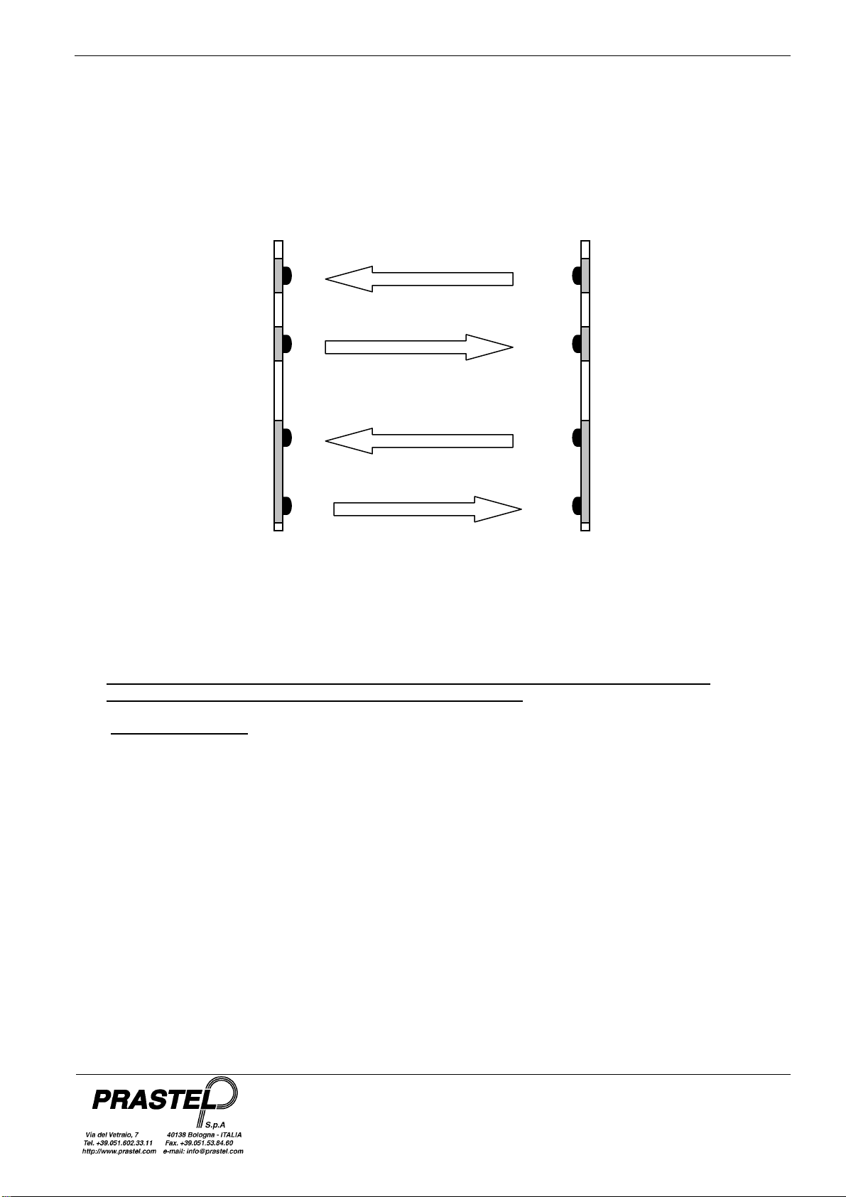
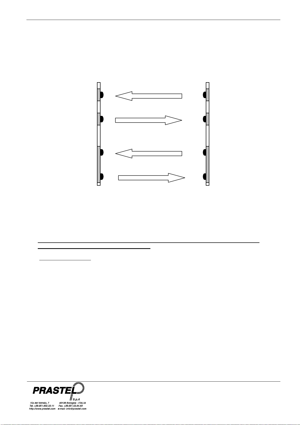
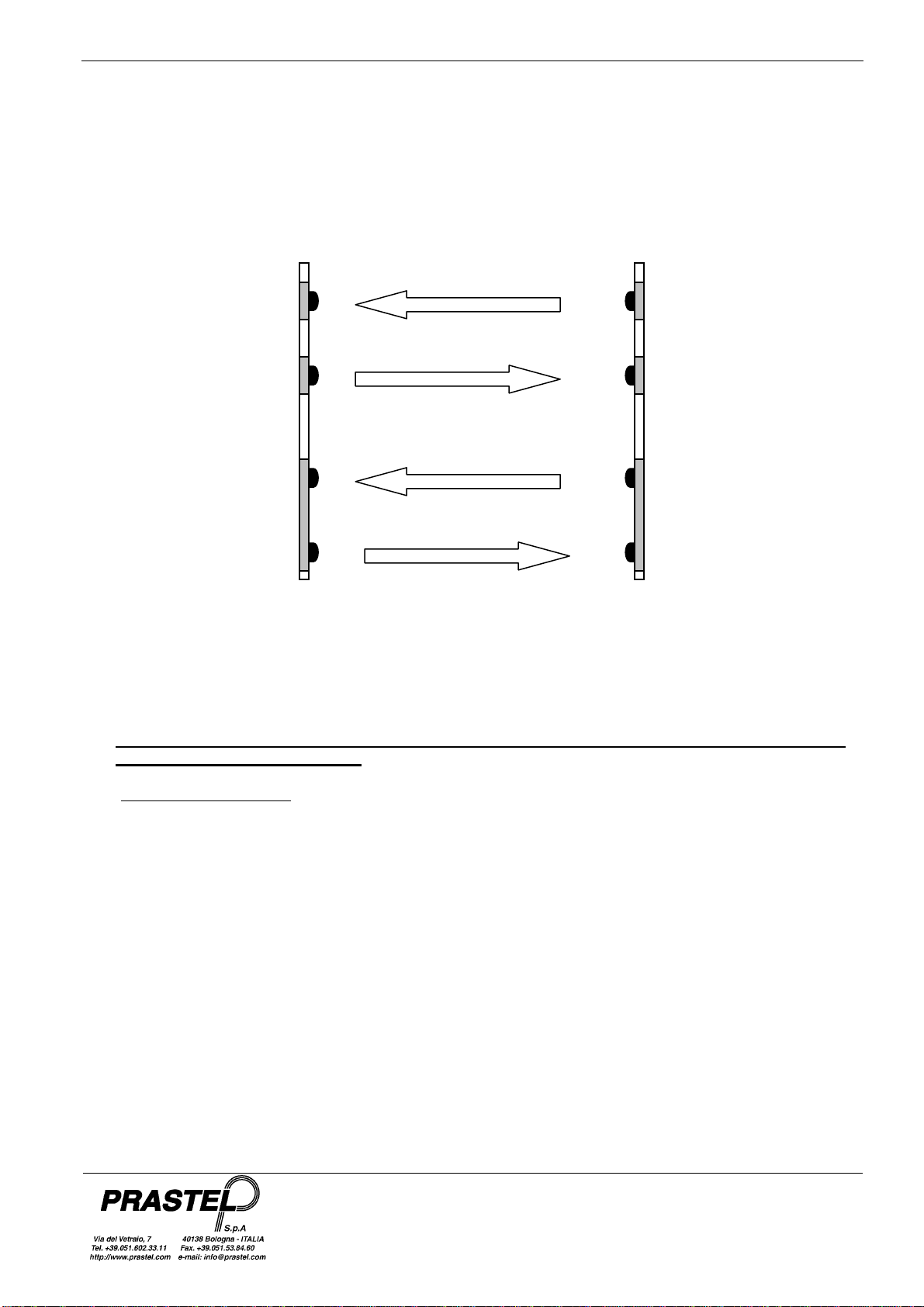
La barrière à infrarouges FSLIMPRO comprend une carte MASTER et une carte SLAVE incorporant le rayon 1,
et un rayon additionnel constitué d'une paire de sondes émetteur TX et récepteur RX.
Chaque rayon est constitué d'un faisceau à infrarouges aller et d'un faisceau à infrarouges retour; la carte
MASTER transmet le signal à la carte SLAVE qui, en cas de bonne réception, le retransmet à la carte MASTER,
se comportant ainsi comme un miroir “électronique”.
La barrière peut gérer jusqu'à quatre rayons (8 faisceaux au total); possibilité d'extension avec les rayons
individuels FSLIMPLUS disponibles en option.
5.
MONTAGE DE LA BARRIERE FSLIMPRO
ATTENTION : SELON L’IMPLANTATION DES BARRIERES LE SOLEIL, PEUT CAUSER DES
PERTURBATIONS ET DECLENCHER DE FAUSSES ALARMES.
5.1 Préparation et fixation
1. Couper les profils en aluminium anodisé noir et le polycarbonate à la mesure désirée, si nécessaire.
2. Repérer les emplacements des perçages pour la fixation murale des profils, pour le passage du câble et
pour l'introduction de la protection antiarrachage, si nécessaire.
3. Percer avec un foret Ø 4 pour la fixation, avec un foret Ø 10,5 pour le passe-fil et avec un foret Ø 7,5 pour
la protection antiarrachage.
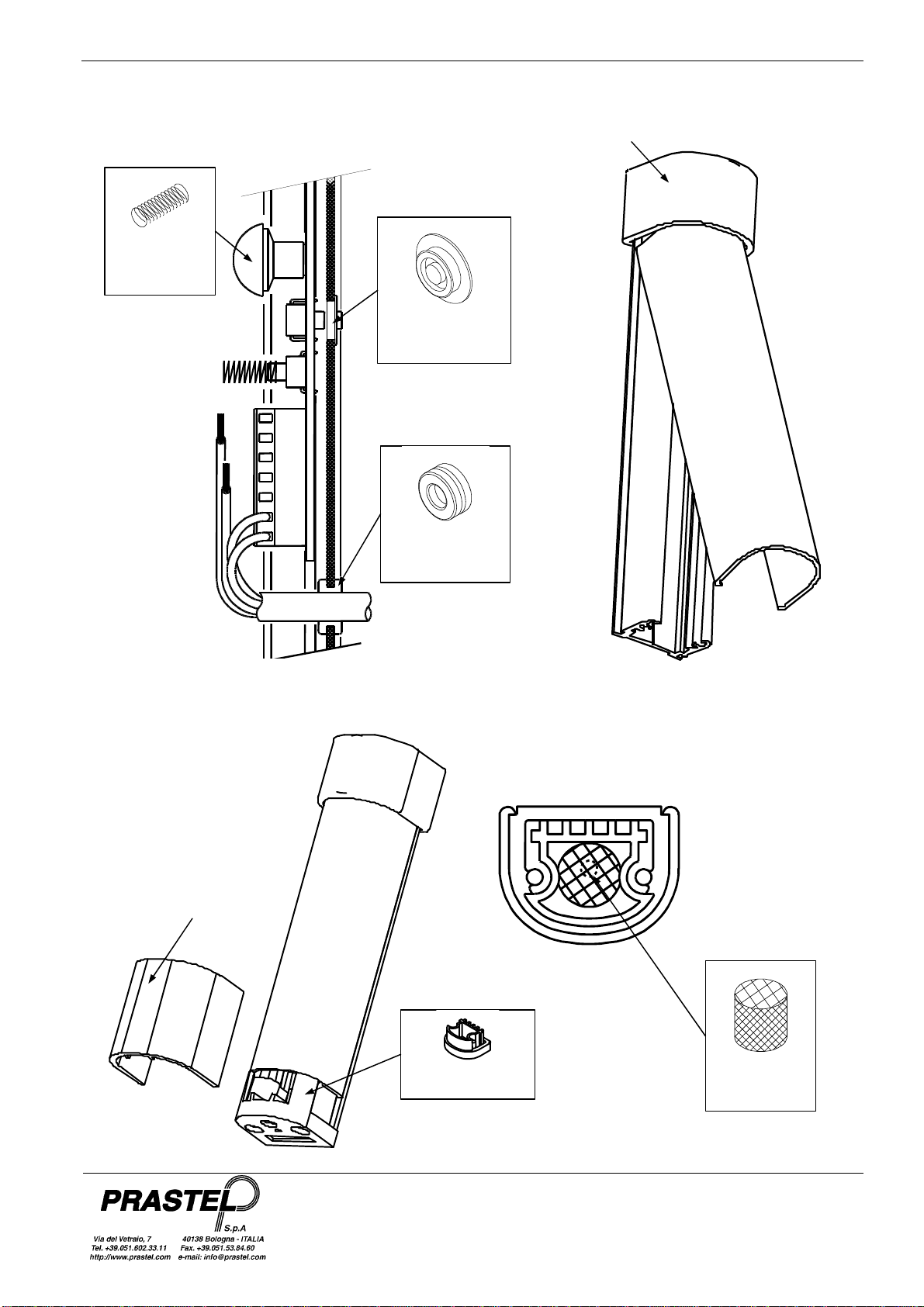
4. Poser les sondes émetteur TX et récepteur RX à l'intérieur des profils dans la position voulue et les fixer
avec la vis autotaraudeuse fournie (Fig. 1)
5. Dénuder le câble multipolaire d'alimentation et les contacts de protection et d'alarme.
6. Introduire le passe-fil dans le profil et faire passer le câble dans le passe-fil (Fig. 2).
7. Introduire le bouchon caoutchouc à l'extrémité supérieure du profil (Fig. 3).
8. Introduire l'éponge dans le bouchon plastique de façon à couvrir le trou d'évacuation de la condensation.
Enfiler le bouchon plastique dans le profil (Fig. 5).
9. Insérer les actionneurs en caoutchouc de la protection antiarrachage dans les trous prévus à cet effet et
insérer les ressorts sur les protections antiouverture (Fig. 2).
10. Fixer les profils au mur au moyen des vis de fixation et de leurs joints toriques.
11. Placer le câble plat des sondes dans le profil et le bloquer avec la griffe fournie (Fig. 1).
12. Relier les câbles d'alimentation et d'alarme comme indiqué ci-dessus et alimenter la barrière sous une
tension de 12Vcc. La barrière fonctionne alors avec les paramètres par défaut.
MASTER SLAVE
TX
TX
RX
RX TX
RX
TX
RX
RAYON 1
RAYON 2

FSLIMPRO05 - 10 - 15 - 20 - 25
FRANÇAIS
ISFSLIMPRO_10_12_fra.doc
13. Vérifier l'alignement des rayons en contrôlant si les leds rouges qui se trouvent sur la carte MASTER et sur
la carte SLAVE sont éteintes ainsi que leur facilité d'interruption.
Leds rouges de
signalisation
alignement rayons
La led rouge sur la carte MASTER est allumée quand le rayon correspondant est désactivé ou bien qu'il est
interrompu ou désaligné soit sur le parcours MASTER vers SLAVE soit sur le parcours SLAVE vers MASTER.
La led rouge sur la carte SLAVE est allumée quand le rayon correspondant est désactivé ou bien qu'il est
interrompu ou désaligné sur le parcours MASTER vers SLAVE.
14. Monter le capot en polycarbonate comme l'indique la Fig. 3.
15. Monter le ressort en plastique, qui sert à recouvrir les éventuelles irrégularités dues à la coupe du profil, sur
le bouchon plastique Fig. 4.
16. Une fois l'installation terminée, recontrôler l'alignement des rayons.
5.2 Programmations et réglages
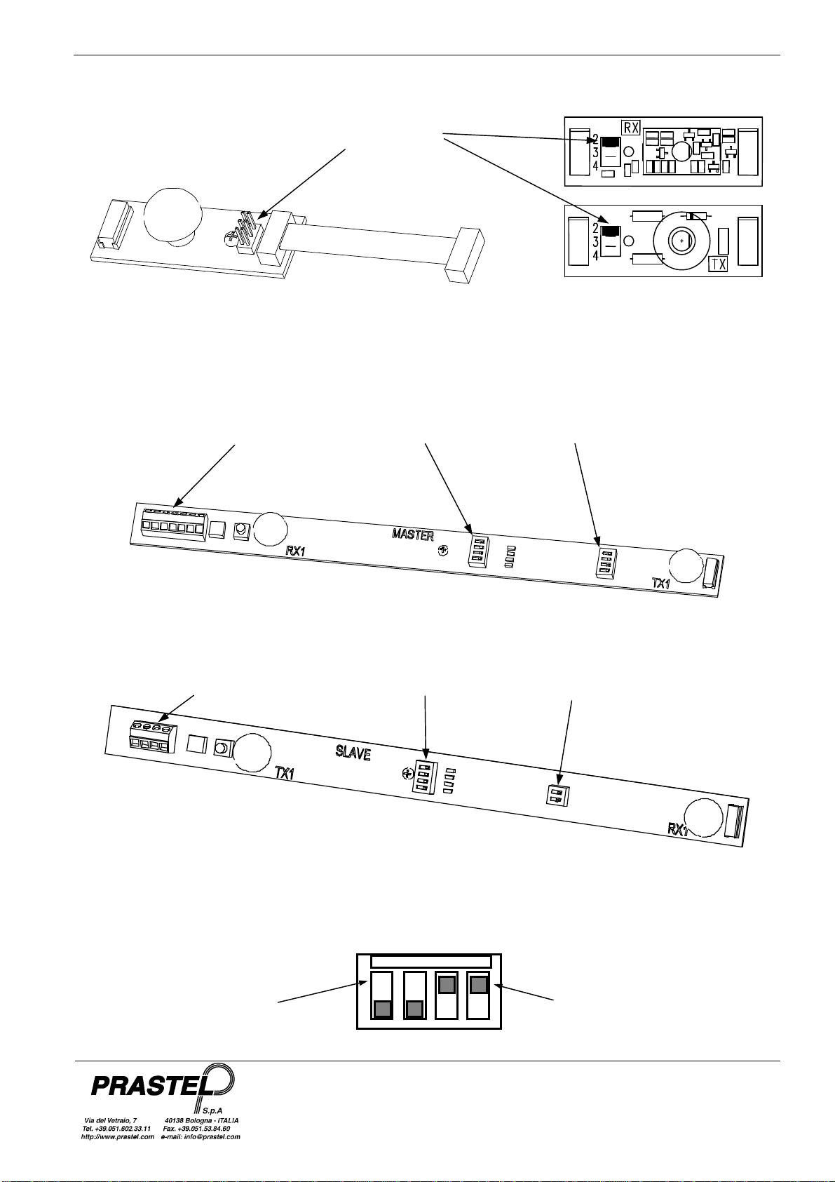
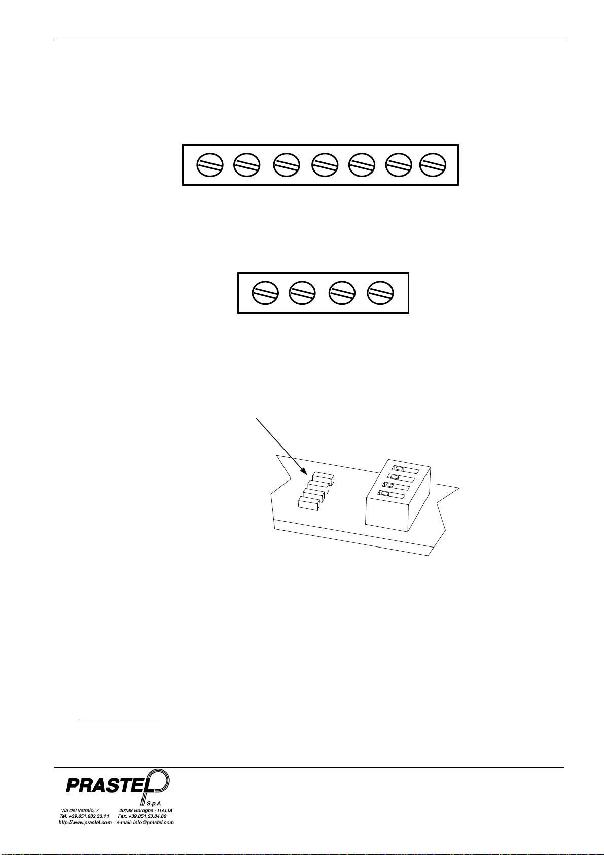
1. N'activer que les rayons connectés:
Sur les sondes TX et RX identifier le rayon (2,3,4) avec le cavalier à disposition en tenant compte du fait
que chaque rayon doit être composé d'un faisceau aller et d'un faisceau retour (voir par. 4).
Bornier Master
+12V GND NC C NO TAMPER
Bornier Slave
+12V GND TAMPER

FSLIMPRO05 - 10 - 15 - 20 - 25
FRANÇAIS
ISFSLIMPRO_10_12_fra.doc
Sélection du
rayon 2, 3 ou 4
Sur les cartes MASTER et SLAVE mettre en position OFF les commutateurs DIP “RAGGI/BEAMS” des rayons
utilisés,
Bornier
MASTER Sélection
rayons
Sélection alarme
et portée
FSLIMPRO - MASTER
Sélection
portée
Sélection
Rayons
Bornier
SLAVE
FSLIMPRO - SLAVE
BEAMS/RAGGI
ON
OFF
Rayon
activé
1 2 3 4
Rayon
désactivé

FSLIMPRO05 - 10 - 15 - 20 - 25
FRANÇAIS
ISFSLIMPRO_10_12_fra.doc
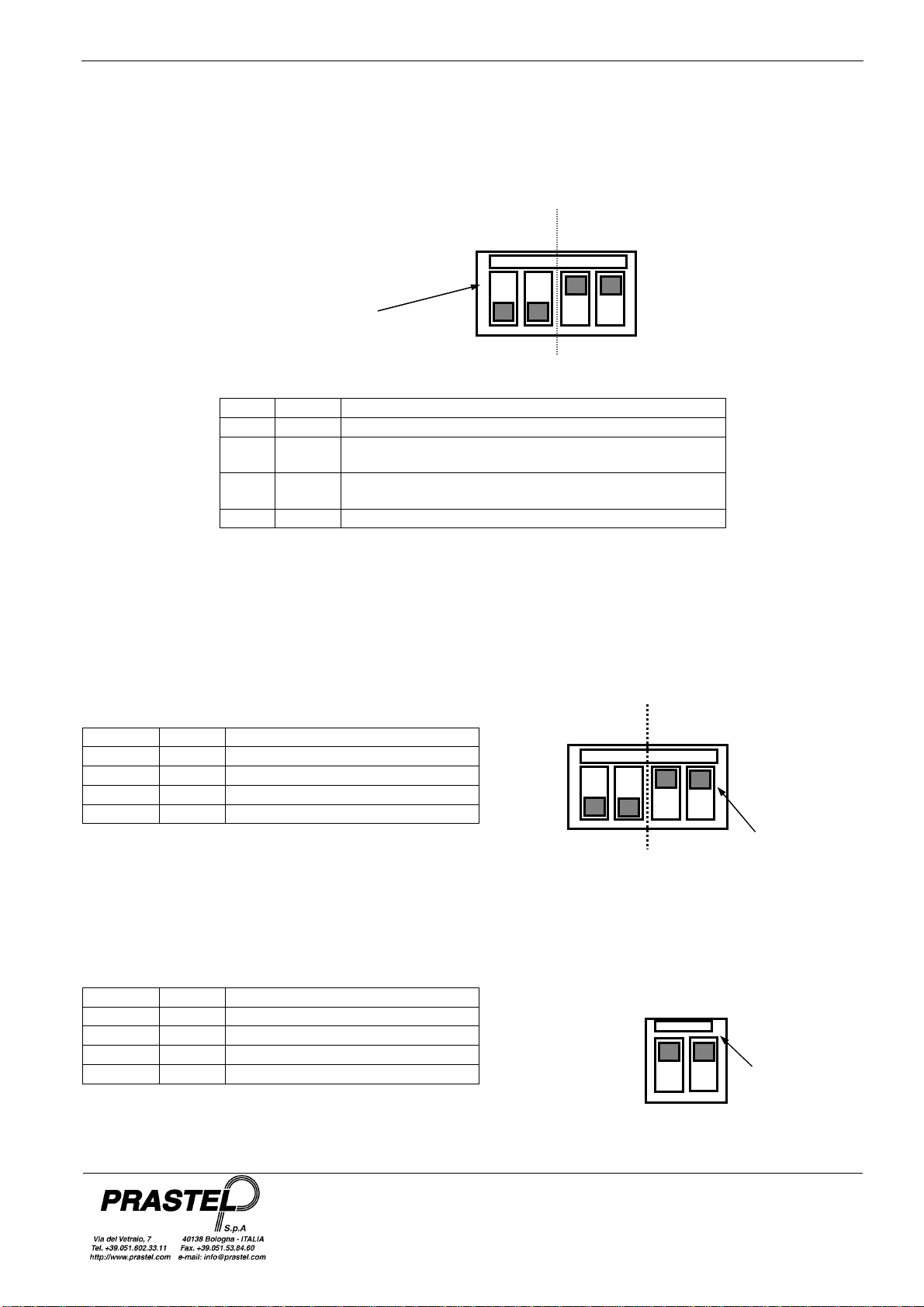
2. Sélectionner le mode d'alarme désiré avec les commutateurs DIP “FUNCTION” 1 et 2 de la carte Master
Dip 1
Dip 2 Activation alarme
OFF OFF Un rayon interrompu pendant au moins 0,1seconde
ON OFF Au moins deux rayons adjacents interrompus pendant
200msec ou deux rayons non adjacents pendant
500msec
OFF ON Au moins deux rayons adjacents interrompus pendant
200msec ou un rayon pendant 1 seconde
ON ON Un rayon interrompu pendant au moins 1 seconde
3. Sélectionner l'intensité des rayons avec les commutateurs DIP “RANGE” 3 et 4 de la carte Master et avec
les commutateurs DIP “RANGE” 1 et 2 de la carte Slave selon la distance des profils et des conditions
ambiantes. En général, il faut effectuer la même sélection sur la carte MASTER et sur la carte SLAVE.
Master
Dip 3 Dip 4 Distance maxi profils interne/externe
ON ON 10/6 mètres
ON OFF 7/4 mètres
OFF ON 4/2 mètres
OFF OFF 2/1 mètres
Slave
Dip 1 Dip 2 Distance maxi profils interne/externe
ON ON 10/6 mètres
ON OFF 7/4 mètres
OFF ON 4/2 mètres
OFF OFF 2/1 mètres
ON
OFF
FUNCTION
Mode
Activation
Alarme
1 2 3 4
RANGE
RANGE
OFF
ON
Portée
rayons
1 2
OFF
ON
FUNCTION
1 2 3 4
Portée
rayons
RANGE
FSLIMPRO05 - 10 - 15 - 20 - 25
FRANÇAIS
ISFSLIMPRO_10_12_fra.doc
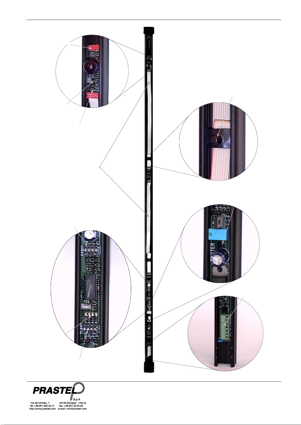
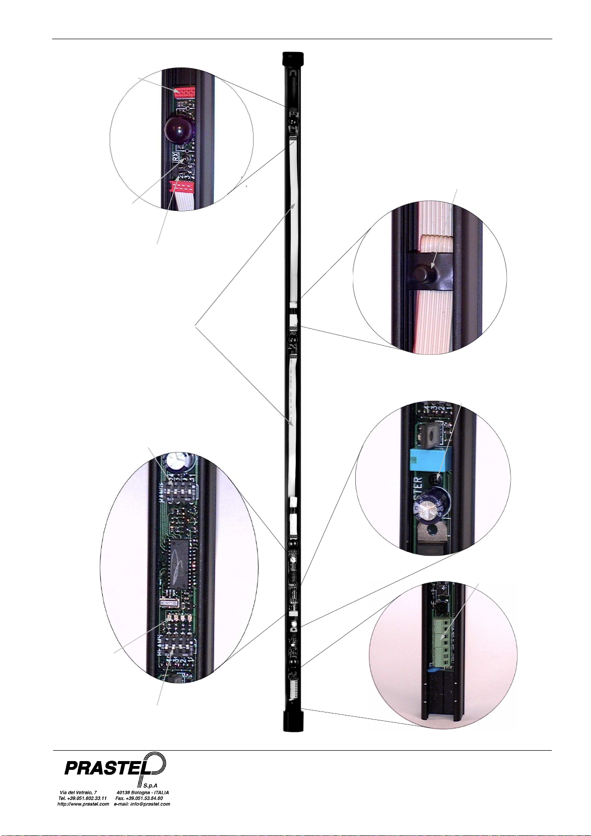
Vis de fixation
de carte RX
Cavalier de sélection
du rayon
Câble plat de
connexion de la
sonde
Connecteur pour
les rayons
suppleméntaires
Ressort de serrage
du câble plat
Bornie
Vis de fixation de
l'amplificateur
Dip switch
Sélection Rayons
Leds rouges de
signalisation
alignement
rayons
Dip switch
Sélection alarme
et portée
Fig. 1

FSLIMPRO05 - 10 - 15 - 20 - 25
FRANÇAIS
ISFSLIMPRO_10_12_fra.doc
BOUCHON
CAOUTCHOUC
BOUCHON
PLASTIQUE
CAPOT
Fig. 5
EPONGE
Fig. 4
Fig. 3
Fig. 2
PASSE-FIL
PROTECTION
ANTIARRACHAGE
RESSORT
PROTECTION
BOUCHON
PLASTIQUE

FSLIMPRO05 - 10 - 15 - 20 - 25
ENGLISH
ISFSLIMPRO_10_12_uk.doc
1. INTRODUCTION
FSLIMPRO is especially designed and built for quick and easy installation. Installation is truly made easy
and wiring up is minimised (only the power supply cable and alarm contacts require wiring up) thanks to the
electronics incorporated in the sections and to the fact that there are no synchronism signals to be
transmitted by wire.
Sections are available in a number of lengths (from 1 to 2.5 m) so as to perfectly satisfy all protection
requirements. Fastening screws with appropriate O rings and specially shaped plugs guarantee perfect
section anchoring and seal, and durable outdoor installations.
Probe positioning to the desired height inside the FSLIMPRO so as to optimise barrier security as required is
easy and reliable thanks to the specially shaped aluminium sections and the fool-proof probe fastening
system.
2. MAIN FEATURES
•Sections in aluminium
•Top end plug in rubber and bottom end one in ABS with sponge pad protected aperture in the bottom for
air circulation against the risk of misting over because of condensate build-up inside the column and of
insects getting in and damaging the photocells.
•Cover in polycarbonate.
•Screws and O rings for secure wall anchoring.
•Equipped with four pairs of transmitter + receiver probes.
•Possibility of using up to 8 pairs of probes.
•Sliding on appropriate guide inside the Transmitter and Receiver probes and fastening by means of
screws.
•A tear-proof and anti-opening tamper on each column.
•Complete with cable routing bush hole for 6mm external diameter cable.
•Incorporated photocell amplifier with the following technical features:
multiplex and synchronised system;
management of up to 8 beams with 2 by 2 selection;
1 N.O./N.C exchange relay output.
•Easy installation and probe alignment thanks to four levels of intensity of the infra-red beams.
•Enabling of beams used by means of the four contact “BEAMS” Dip-Switch.
•Beam status indicator LED:
on = beam broken off or disabled
off = beam aligned or not broken off
•Operating mode selection via “FUNCTION” (1 and 2 ) Dip-Switch, as described in the following table:
Dip 1
Dip 2 Alarm activation
OFF OFF Beam broken off for at least 0.1seconds
ON OFF At least two adjacent beams broken off for 200msec,
or two non-adjacent ones for 500msec
OFF ON At least two adjacent beams broken off for 200msec,
or one beam for 1second
ON ON One beam broken off for 1 second
3.
TECHNICAL SPECIFICATIONS
Power supply 12Vdc
Power consumption
Electric current requirement Max. 1.5 W
Max 50mA (4 pairs of enabled beams)
I.R. wave length 950 nm
Operating range 10 metres indoors / 6 metres outdoors
Relay outputs (clean exchange contact) N.O. / N.C
Relay response time Minimum 100ms, maximum 1second
Reset time 0.5 seconds
Working temperature range -20 °C to +55 °C
FSLIMPRO05 - 10 - 15 - 20 - 25
ENGLISH
ISFSLIMPRO_10_12_uk.doc
4.
OPERATING PRINCIPLE
The FSLIMPRO infra-red beam barrier comprises a MASTER and a SLAVE card with beam 1 on-board, and an
additional beam made up of a pair of TX transmitter and RX receiver probes.
Each beam consists of a pair of signals, one outgoing the other incoming. The former is transmitted by the
MASTER card to the Slave card that upon correctly receiving the signal relays it back to the MASTER card, thus
practically acting like an “electronic” mirror.
The barrier is capable of managing up to four pairs of beams (8 beams overall). Single beam expansions are
available on request (use code FSLIMPLUS when ordering).
5 INSTALLING FSLIMPRO
WARNING : ACCORDING TO BARRIERS INSTALLATION LOCATION, THE SUN MAY CREATE
DISRUPTIONS AND TRIGGER FALSE-ALARMS.
5.1 Mounting and wiring up
1. If necessary, cut the black anodised sections and the polycarbonate to the desired lengths and sizes.
2. Identify points where to drill the holes for fastening the sections to the wall, for wire routing, and for inserting
the tear-proof tamper if necessary.
3. Use a Ø 4 bit to drill the fastening holes, a Ø 10.5 one for the wire routing hole, and a Ø 7.5 one for the tear-
proof tamper hole.
4. Position the TX Transmitter and RX Receiver probes inside the sections as desired and fasten into place by
means of the self-threading screws provided (see Figure 1).
5. Strip the multi-pole power cable and the tamper and alarm contacts.
6. Insert the wire routing bush hole onto the section and route in the cable (see Figure 2).
7. Insert the rubber plug at the top end of the section (see Figure 3).
8. Fit the sponge pad inside the plastic plug so as to cover the condensate drain hole. Insert the plastic plug
inside the section (see Figure 5).
9. Insert the rubber tear-proof tamper actuators into the appropriate holes and fit the clips onto the anti-
opening tampers (see Figure 2).
10. Secure the sections to the wall by means of the fastening screws and relevant O rings.
11. Fit the flat probe cable into the section and fasten down with the clip provided (see Figure 1).
12. Wire up power and alarm connections as shown below and power the barrier with 12 Vdc. The barrier is
now fully operative with all due default settings.
MASTER SLAVE
TX
TX
RX
RX TX
RX
TX
RX
BE
AM 1
BEAM 2

FSLIMPRO05 - 10 - 15 - 20 - 25
ENGLISH
ISFSLIMPRO_10_12_uk.doc
13. Check that MASTER and SLAVE red LEDS go off indicating proper beam alignment and also check for
easy beam break off.
Red LEDs indicating
proper beam
alignment (when off
)
The MASTER red LED comes on when the corresponding beam is disabled, or broken off or not properly
aligned in the MASTER to SLAVE or SLAVE to MASTER stretch.
The SLAVE red LED comes on when the corresponding beam is disabled, or broken off or not properly aligned
in the MASTER to SLAVE stretch.
14. Fit on the polycarbonate cover as shown in Figure 3.
15. Fit the plastic clip on to the plastic plug to cover up any roughly cut edges as shown in Figure 4.
16. Make a last check of the installation and a final alignment of the beams.
5.2 Settings and adjustments
1. Only enable connected beams:
identify connected beams (2,3,4) in the TX and RX probes by means of the jumper, bearing in mind that
beams come in pairs as they consist of an outgoing and an incoming probe (see par. 4).
Master Term. Strip
+12V GND NC C NO TAMPER
Slave Term. Strip
+12V GND TAMPER
FSLIMPRO05 - 10 - 15 - 20 - 25
ENGLISH
ISFSLIMPRO_10_12_uk.doc
Beam 2, 3 or 4
Selection
In the MASTER and SLAVE boards set in OFF position the “BEAM” DIP SWITCHES referred to the used
beams.
MASTER
Terminal strip beam
selection alarm and range
selection
FSLIMPRO - MASTER
range
selecti
on
beam
selection
SLAVE
Terminal strip
FSLIMPRO - SLAVE
ON
OFF
BEAMS
Beam
enabled
1 2 3 4
Beam
disabled

FSLIMPRO05 - 10 - 15 - 20 - 25
ENGLISH
ISFSLIMPRO_10_12_uk.doc
2. Select desired alarm mode with Master “FUNCTION” 1 and 2 Dip Switches.
Dip 1
Dip 2 Alarm activation
OFF OFF One beam broken off for at least 0.1seconds
ON OFF At least due adjacent beams broken off for 200msec,
or two non-adjacent beams for 500msec
OFF ON At least two adjacent beams broken off for 200msec,
or one beam for 1second.
ON ON A beam broken off for at least 1 second
3. Select beam intensity with Master “RANGE” 3 and 4 Dip Switches and Slave “RANGE” 1 and 2 Dip
Switches depending on distance profiles and environmental conditions. MASTER and SLAVE normally
require the same setting.
Master
Dip 3 Dip 4 Max. in-/outdoor distance profiles
ON ON 10/6 metres
ON OFF 7/4 metres
OFF ON 4/2 metres
OFF OFF 2/1 metres
Slave
Dip 1 Dip 2 Max. in-/outdoor distance profiles
ON ON 10/6 metres
ON OFF 7/4 metres
OFF ON 4/2 metres
OFF OFF 2/1 metres
ON
OFF
FUNCTION
Alarm
Activation
Mode
1 2 3 4
RANGE
OFF
ON
RANGE
Beam Range
1
2
ON
OFF
FUNCTION
1 2 3 4
Beam
Range
RANGE

FSLIMPRO05 - 10 - 15 - 20 - 25
ENGLISH
ISFSLIMPRO_10_12_uk.doc
Fig. 1
RX card
locking screw
Beam selection
jumper
Flat probe
connection cable
Connector for
additional beams
Flat cable
fastening clip
Terminal Strip
Amplifier locking
screw
Beam selection
Dip switch
Red LEDs
indicating
proper beam
alignment
(when off
)
Dip switch
alarm
and range selection
FSLIMPRO05 - 10 - 15 - 20 - 25
ENGLISH
ISFSLIMPRO_10_12_uk.doc
Fig. 5
SPONGE
PAD
CABLE ROUTING
BUSH
Fig. 4
Fig. 3
Fig. 2
TEAR-PROOF
TAMPER
TAMPER
SPRING CLIP
RUBBER PLUG
PLASTIC PLUG
PLASTIC
PLUG
COVER

FSLIMPRO05 - 10 - 15 - 20 - 25
ITALIANO
ISFSLIMPRO_10_12_it.doc
1. INFORMAZIONI GENERALI
Il FSLIMPRO è stato appositamente studiato e realizzato per una facile e rapida installazione. L’elettronica
incorporata nei profili e la mancanza di segnali di sincronismo via cavo semplificano l’installazione e
riducono al minimo la posa dei cavi di collegamento (solo l’alimentazione e contatti di allarme).
La disponibilità di profili di varie misure (da 1 a 2,5 m) permette di adeguare la protezione a seconda delle
specifiche esigenze. Il fissaggio tramite viti ed ORing dei profili e la particolare sagoma dei tappi
garantiscono la tenuta del fissaggio e consentono l’impiego in ambiente esterno.
Grazie alla sagoma del profilo in alluminio ed al semplice sistema di fissaggio delle sonde è possibile
posizionarle all’interno del FSLIMPRO, all’altezza desiderata ottimizzando la barriera di sicurezza a seconda
delle proprie esigenze.
2. CARATTERISTICHE PRINCIPALI
•Profilo in alluminio
•Tappo superiore in gomma ed inferiore in ABS con un foro nel fondo protetto da una spugna che
consente il passaggio dell’aria evitando sia fenomeni di appannamento all’interno delle colonne che
intrusioni di insetti che potrebbero causare danno alle fotocellule
•Copertura in policarbonato
•Fissaggio a parete tramite viti ed ORing forniti in dotazione
•Dotazione di quattro coppie di sonde trasmettitore + ricevitore
•Possibilità di impiego fino a 8 coppie di sonde
•Scorrimento sull’apposita guida interna delle sonde Trasmettitore e Ricevitore e fissaggio tramite vite
•Dotazione di tamper antiapertura ed antistrappo (escludibile mediante jumper NO TAMPER) per ogni
colonna
•Dotazione di passacavo per cavo diametro esterno 6mm.
•Amplificatore fotocellula incorporato con le seguenti caratteristiche tecniche:
Sistema multiplexato e sincronizzato
Gestione fino a 8 raggi selezionabili 2 a 2.
1 uscita a relè in scambio N.O./N.C
•Facilità di installazione e di allineamento delle sonde grazie a quattro livelli di intensità’ dei raggi
infrarossi.
•Abilitazione dei raggi utilizzati mediante il Dip-Switch “BEAMS/RAGGI” a quattro contatti.
•LED di segnalazione dello stato dei raggi (escludibile mediante jumper LED OFF):
acceso = raggio interrotto o disabilitato
spento = raggio allineato e non interrotto
•Modalità di funzionamento selezionabili con il Dip-Switch “FUNCTION” (1 e 2 ), come indicato dalla
seguente tabella:
Dip 1
Dip 2 Attivazione allarme
OFF OFF Un raggio interrotto per almeno 0,1secondi
ON OFF Almeno due raggi adiacenti interrotti per 200msec, o
due raggi non adiacenti per 500msec
OFF ON Almeno due raggi adiacenti interrotti per 200msec
o un raggio per 1secondo
ON ON Un raggio interrotto per almeno 1 secondo
3.
CARATTERISTICHE TECNICHE
Alimentazione 12Vdc
Potenza assorbita
Corrente Assorbita Max. 1.5 W
Max 50mA (4 coppie di raggi abilitati)
Lunghezza d’onda I.R. 950 nm
Portata 10 metri in interno / 6 metri in esterno
Uscite a relè (contatto pulito in scambio) N.A. / N.C
Tempo d’intervento del relè Minimo 100ms massimo 1secondo
Tempo di ripristino 0,5 secondi
Temperatura di Funzionamento -20 °C ÷+55 °C
FSLIMPRO05 - 10 - 15 - 20 - 25
ITALIANO
ISFSLIMPRO_10_12_it.doc
4
. PRINCIPIO DI FUNZIONAMENTO
La barriera ad infrarossi FSLIMPRO è composta da una scheda MASTER ed una SLAVE con a bordo il raggio
1, e da un raggio aggiuntivo composto da una coppia di sonde trasmettitore TX e ricevitore RX.
Ogni raggio è composto da un fascio ad infrarossi in andata ed uno di ritorno; il MASTER trasmette il segnale
allo SLAVE che, se lo riceve correttamente, lo ritrasmette al MASTER comportandosi come uno specchio
“elettronico”.
La barriera può gestire fino a quattro raggi (8 fasci in totale), per espanderla è possibile acquistare i singoli raggi
col codice FSLIMPLUS.
5. MONTAGGIO FSLIMPRO
ATTENZIONE : SECONDO L’IMPIANTO DELLE BARRIERE, IL SOLE PUÔ CREARE PERTURBAZIONI
E PROVOCARE FALSI ALLARME.
5.1 Preparazione e fissaggio
1. Tagliare i profili in alluminio anodizzato nero ed il policarbonato alla misura desiderata se necessario.
2. Individuare i punti ove eseguire la foratura per il fissaggio dei profili alla parete, per il passaggio del cavo e
per l’introduzione del tamper antistrappo se necessario.
3. Forare con punta Ø 4 per il fissaggio, con punta Ø 10,5 per il passacavo e con punta Ø 10,5 per il tamper
antistrappo.
4. Posizionare le sonde Trasmettitore TX e Ricevitore RX all’interno dei profili nella posizione desiderata e
fissarle con la vite autofilettante in dotazione (Fig. 1)
5. Spelare il cavo multipolare per l’alimentazione ed i contatti tamper e di allarme.
6. Introdurre il passacavo nel profilo e far passare il cavo all’interno del passacavo (Fig. 2).
7. Inserire il tappo in gomma all’estremità superiore del profilo (Fig. 3).
8. Introdurre la spugnetta nel tappo in plastica in modo da coprire il foro di scarico della condensa. Infilare il
tappo in plastica nel profilo (Fig. 5).
9. Inserire gli azionatori in gomma del tamper antistrappo negli appositi fori, ed inserire le molle sui tamper
antiapertura (Fig. 2). Se non si vuole usare il tamper antistrappo controllare che sia inserito il jumper NO
TAMPER.
10. Fissare i profili alla parete mediante le viti di fissaggio ed i relativi OR.
11. Sistemare il cavo piatto delle sonde all’interno del profilo e bloccarlo con la molletta fornita in dotazione (Fig.
1).
12. Collegare i cavi di alimentazione e di allarme come sottoindicato ed alimentare la barriera con una tensione
di 12Vdc. A questo punto la barriera è già funzionante con i settaggi di default.
MASTER SLAVE
TX
TX
RX
RX TX
RX
TX
RX
RAGGIO 1
RAGGIO 2
FSLIMPRO05 - 10 - 15 - 20 - 25
ITALIANO
ISFSLIMPRO_10_12_it.doc
13. Verificare l’allineamento dei raggi con lo spegnimento dei led rossi presenti sul MASTER e sullo SLAVE e la
loro facilità d’interruzione.
Led rossi
segnalazione
allineamento
raggi
Il led rosso sul MASTER è acceso quando il raggio corrispondente è disabilitato oppure è interrotto o disallineato
o nel tratto da MASTER a SLAVE o nel tratto da SLAVE a MASTER.
Il led rosso sullo SLAVE è acceso quando il raggio corrispondente è disabilitato oppure è interrotto o disallineato
nel tratto da MASTER a SLAVE.
Completato l’allineamento dei raggi è possibile spegnere i quattro led rossi, chiudendo il jumper LED OFF sia
sulla scheda Master che sulla scheda Slave.
14. Montare la copertura in policarbonato come indicato nella Fig. 3.
15. Montare la molla in plastica, che serve a ricoprire eventuali irregolarità nel taglio del profilo, sul tappo
plastico Fig. 4.
16. Ricontrollare ad installazione ultimata l’allineamento dei raggi
5.2 Settaggi e tarature
1. Abilitare i soli raggi collegati:
nelle sonde TX ed RX identificare il raggio (2,3,4) con il ponticello a disposizione tenendo conto che ogni
raggio è composto da un fascio di andat ed uno di ritorno (vedi par. 4).
Morsettiera Master
+12V GND NC C NO TAMPER
Morsettiera Slave
+12V GND TAMPER

FSLIMPRO05 - 10 - 15 - 20 - 25
ITALIANO
ISFSLIMPRO_10_12_it.doc
Selezione del
raggio 2, 3 o 4
nelle schede MASTER e SLAVE porre ad OFF i DIP “RAGGI/BEAMS” dei raggi impiegati,
Jumper
NO TAMPER
Jumper
LED OFF
Selezione
allarme e portata
FSLIMPRO - MASTER
Selezione
raggi
Morsettiera
MASTER
Jumper
NO TAMPER
Selezione
raggi Selezione
portata
FSLIMPRO - SLAVE
Jumper
LED OFF
Morsettiera
SLAVE
BEAMS/RAGGI
Raggi
abilitati
(esempio)
Raggi
disabilitati
(esempio)
ON
OFF
1 2 3 4
FSLIMPRO05 - 10 - 15 - 20 - 25
ITALIANO
ISFSLIMPRO_10_12_it.doc
2. Selezionare la modalità di allarme desiderata con i DIP “FUNCTION” 1 e 2 del Master
Dip 1
Dip 2 Attivazione allarme
OFF OFF Un raggio interrotto per almeno 0,1secondi
ON OFF Almeno due raggi adiacenti interrotti per 200msec, o
due raggi non adiacenti per 500msec
OFF ON Almeno due raggi adiacenti interrotti per 200msec
o un raggio per 1secondo
ON ON Un raggio interrotto per almeno 1 secondo
3. Selezionare l’intensità dei raggi con i Dip “RANGE” 3 e 4 del Master e con i Dip “RANGE” 1 e 2 dello Slave
in funzione della distanza dei profili e delle condizioni ambientali. In generale occorre eseguire lo stesso
settaggio sia sul MASTER che sullo SLAVE.
Master
Dip 3 Dip 4 Distanza max profili interno/esterno
ON ON 10/6 metri
ON OFF 7/4 metri
OFF ON 4/2 metri
OFF OFF 2/1 metri
Slave
Dip 1 Dip 2 Distanza max profili interno/esterno
ON ON 10/6 metri
ON OFF 7/4 metri
OFF ON 4/2 metri
OFF OFF 2/1 metri
ON
OFF
FUNCTION
Modalità
Attivazione Allarme
1 2 3 4
RANGE
OFF
ON
RANGE
1 2
ON
OFF
FUNCTION
1 2 3 4
RANGE
Portata
Raggi
Portata
Raggi
FSLIMPRO05 - 10 - 15 - 20 - 25
ITALIANO
ISFSLIMPRO_10_12_it.doc
Vite di fissaggio
scheda RX
Jumper selezione
raggio
Cavo piatto di
collegamento sonde
Connettore per
espansione
raggi
Molla bloccaggio
cavo piatto
Morsettiera
Vite di fissaggio
amplificatore
Dip switch
selezione raggi
Led rossi
allineamento
raggi
Dip switch
selezione portata
e funzioni
This manual suits for next models
5
Table of contents
Languages:
Other PRASTEL Accessories manuals


