PRASTEL FOTOTEST/2 User manual

FOTOTEST/2
PRASTEL S.r.l.
Via del Vetraio, 7 40138 Bologna Italy - Tel. +39-051-6023311 Fax +39-051-538460
E-mail: info@prastel.com - Web site: http://www.prastel.com
FOTOTEST/2 01/1999.DOC
MEMBER OF
ITALIANO
1. DESCRIZIONE GENERALE
L’amplificatore fotocellula a 2 raggi indipendenti FOTOTEST/2 è stata ideato, progettato e costruito con lo scopo di
garantire, in abbinamento ad apposite sonde, la massima sicurezza in un accesso automatizzato; Es: ascensori, bussole
antirapina, porte automatiche, basculanti, industriali, etc… Può essere utilizzato sia posizionando le sonde dirattamente
sul varco, che all’interno di una o più coste di sicurezza.
La conformità ai rigidi standard Europei (CE) è inoltre garanzia di qualità ed affidabilità del prodotto.
Infatti l’abbinamento con centraline di comando motori conformi alla “Direttiva macchine 89/392/CEE” (quali le centraline
Prastel della famiglia Euromatic) consente di utilizzare la funzione di autotest tramite la quale viene controllato il corretto
funzionamento dello stesso amplificatore fotocellula al ricevimento dell’ impulso di autotest
2. CARATTERISTICHE PRINCIPALI
•Gestione di due raggi indipendenti
•Due uscite a relè N.C. corrispondenti ai due raggi indipendenti
•Autotest di corretto funzionamento
•Selezione del livello di autotest tramite jumper (> 12-24 Vdc oppure < 5 Vdc)
•Facilità di installazione e di allinemento delle sonde grazie alla funzione
“Install check” di attenuazione dell’intensità dei raggi infrarossi.
•Abbinabile alle sonde Prastel attuali modelli
CR/9MS, CR/9MS9, CR/9MSD, CR/9MSP, CR/FC, CR/20MS
•Conformità alla normativa UNI 8612
•Conforme alle Direttive Europee di riferimento:
Direttiva Macchine 89/392/CEE
Compatibilità Elettromagnetica (EMC) 89/336/CEE
3. CARATTERISTICHE TECNICHE
Alimentazione 12÷24 Vac/dc ±10%
Potenza assorbita Max. 1 W (2 raggi)
Lunghezza d’onda I.R. 850 nm.
Portata 5 ÷ 20 m nominali
Temperatura di Funzionamento -20 °C / +70 °C
Tempo d’intervento del relè 20 ms
Tempo di ripristino 0,5 s
Peso 520 g
4. COLLEGAMENTO E MESSA IN FUNZIONE DELLA CENTRALINA
•Prima di eseguire l’installazione dell’amplificatore fotocellula FOTOTEST/2 leggere le “Avvertenze generali per la
sicurezza”.
•Fissare il box tramite gli appositi fori di fissaggio
•Allineare le sonde (si vedano i modelli citati al punto 2).
•Fare passare i cavi di collegamento negli appositi passacavi
•Collegare i cavi di alimentazione e di segnale.
•Alimentare e verificare che i LED 1 e 2 di allineamento dei raggi siano accesi.
•Selezionare tramite i jumper J1 o J2 il livello di autotest basso o alto (dipende dalla centrale di comando collegata).
•Premere il pulsante di “Install check”; a questo punto l’intensità dei raggi collegati viene ridotta del 40 %. Durante
questa operazione assicurarsi che i LED 1 e 2 rimangano accesi.
•Verificare il corretto funzionamento della funzione di autotest facendo eseguire il comando alla centrale collegata
(solo se la centrale è predisposta per la funzione di autotest). Dopo tale comando i LED abbinati ai raggi 1 e 2 si
spengono e riaccendono e allo stesso tempo commutano i relativi relè dallo stato N.C. allo stato N.O. per poi
ritornare allo stato iniziale N.C. (solo se i raggi erano stati preventivamente collegati e allineati).

FOTOTEST/2
PRASTEL S.r.l.
Via del Vetraio, 7 40138 Bologna Italy - Tel. +39-051-6023311 Fax +39-051-538460
E-mail: info@prastel.com - Web site: http://www.prastel.com
FOTOTEST/2 01/1999.DOC
MEMBER OF
ENGLISH
1. DESCRIPTION
FOTOTEST/2 is a photocell amplifier with two independent beams especially designed and constructed to ensure, when
used in conjunction with appropriate sensors, maximum safety for automatic accesses such as lift doors, burglar-proof
double doors, automatic, overhead and industrial doors, and so on. The device can be mounted by positioning the
sensors either directly in the doorway or inside one or more safety hips.
Product quality and reliability is further ensured by compliance with stringent European standards (EC). In fact,
when used in conjunction with motor control units constructed according to Machinery Directive 89/392/EEC (as
are all Prastel units in the Euromatic series), the system is endowed with a self-test function which permits to
check the proper operation of the photocell amplifier upon receipt of the self-test signal.
2. MAIN FEATURES
•Management of two independent beams
•Two NC relay outputs, one for each independent beam
•Self-test function for proper operation
•Selection of self-test level via jumper (>12-24 Vdc or <5 Vdc)
•Easy installation and alignment of sensors thanks to the “install check” function
for attenuation of the intensity of infrared beams
Possibility of combination with Prastel’s current sensor models:
CR/9MS, CR/9MS9, CR/9MSD, CR/9MSP, CR/FC, CR/20MS
•Compliance with UNI 8612 Standards
•Compliance with European reference directives:
Machinery Directive 89/392/EEC
Electromagnetic Compatibility (EMC) 89/336/EEC
3. TECHNICAL FEATURES
Power supply 12-24 Vac/dc ± 10%
Maximum power input 1W (2 beams)
Infrared wave length 850 nm
Rated range 5 to 20 m
Operating temperature -20 to + 70 °C
Relay response time 20 ms
Reset time 0.5 sec
Weight 520 grams
4. WIRING AND START-UP
•Before installing the FOTOTEST/2 photocell amplifier, carefully read the “General Safety Precautions”.
•Install the box via the appropriate mounting holes.
•Align the sensors (namely any of those cited in point 2 above).
•Route the connection cables through the appropriate fairleads.
•Connect the power and signal cables.
•Power and check that the beam alignment LEDs 1 and 2 come on.
•Select low or high self-test level (depending on the control unit employed) via jumper J1 or J2.
•Press the “install check” button to reduce the intensity of the connected beams by 40%. During this operation, check
that LEDs 1 and 2 always stay on.
Check that the self-test function is properly working by giving a command to the control unit (to be performed only in
case of the unit being set up for the self-test function). Upon this command being given, the LEDs associated with
beams 1 and 2 go off and come back on, while the associated relays simultaneously switch from the NC to the NO
status before returning to their initial NC status (on condition that the beams have been previously duly connected
and aligned).

FOTOTEST/2
PRASTEL S.r.l.
Via del Vetraio, 7 40138 Bologna Italy - Tel. +39-051-6023311 Fax +39-051-538460
E-mail: info@prastel.com - Web site: http://www.prastel.com
FOTOTEST/2 01/1999.DOC
MEMBER OF
FRANÇAIS
1. DESCRIPTION GENERALE
L’amplificateur de photocellule à 2 rayons indépendants FOTOTEST/2 a été conçu, étudié et réalisé pour garantir, en
association avec les sondes appropriées, une sécurité maximum dans un accès automatisé. Par exemple: ascenseurs,
guichets anti-cambriolage, portes automatiques, basculantes, industrielles, etc. On peut l’utiliser soit en plaçant les
sondes directement sur le passage soit à l’intérieur d’un ou plusieurs bourrelets de sécurité.
La conformité aux rigoureux standards européens (CE) garantit également la qualité et la fiabilité du produit.
En effet, en association avec des centrales de commande de moteurs conformes à la « Directive sur les machines
89/392/CEE » (telles que les centrales Prastel de la famille Euromatic), il permet d’utiliser la fonction d’autotest
contrôlant le bon fonctionnement de cet amplificateur à la réception de l’impulsion d’autotest.
2. CARACTERISTIQUES PRINCIPALES
•Gestion de deux rayons indépendants
•Deux sorties à relais N.F. correspondant aux deux rayons indépendants
•Autotest de bon fonctionnement
•Sélection du niveau d’autotest par cavalier (> 12-24 Vcc ou < 5 Vcc)
•Facilité d’installation et d’alignement des sondes grâce à la fonction
« Install check » d’atténuation de l’intensité des rayons infrarouges.
•Pouvant être associé aux sondes Prastel modèles:
CR/9MS, CR/9MS9, CR/9MSD, CR/9MSP, CR/FC, CR/20MS
•Conforme aux normes UNI 8612
•Conforme aux Directives Européennes de référence:
Directive Machines 89/392/CEE
Compatibilité Electromagnétique (EMC) 89/336/CEE
3. CARACTERISTIQUES TECHNIQUES
Alimentation 12 ÷ 24 Vca/cc ±10% (programmable)
Puissance absorbée 1 W maxi (2 rayons)
Longueur d’onde R.I. 850 mm
Portée 5 ÷ 20 m (valeur nominale)
Température de fonctionnement -20 °C ÷ +70 °C
Temps d’intervention du relais 20 ms
Temps de réarmement 0,5 s
Poids 520 g
4. RACCORDEMENT ET MISE EN SERVICE DE LA CENTRALE
•Avant de procéder à l’installation de l’amplificateur de photocellule FOTOTEST/2, lire les « Avertissements généraux
concernant la sécurité ».
•Fixer le boîtier au moyen des trous de fixation prévus à cet effet.
•Aligner les sondes (voir les modèles cités au point 2).
•Faire passer les câbles de liaison dans les passe-fils prévus à cet effet.
•Relier les câbles d’alimentation et de signaux.
•Alimenter et vérifier si les LEDs d’alignement des rayons 1 et 2 sont bien allumées.
•Sélectionner, au moyen des cavaliers J1 ou J2, le niveau d’autotest bas ou haut (dépendant de la centrale de
commande reliée).
•Appuyer sur le bouton « Install check »; l’intensité des rayons reliés est alors réduite de 40%. Pendant cette
opération, s’assurer que les LEDs 1 et 2 restent allumées.
Vérifier le bon fonctionnement de la fonction d’autotest en faisant exécuter la commande à la centrale reliée
(uniquement si la centrale est prévue pour assurer la fonction d’autotest). Après cette commande, les LEDs
associées aux rayons 2 et 2 s’éteignent et se rallument et, en même temps, les relais correspondants passent de
l’état N.F. à l’état N.O puis reviennent ensuite à l’état initial N.F. (uniquement si les rayons ont été préalablement
reliés et alignés).

FOTOTEST/2
PRASTEL S.r.l.
Via del Vetraio, 7 40138 Bologna Italy - Tel. +39-051-6023311 Fax +39-051-538460
E-mail: info@prastel.com - Web site: http://www.prastel.com
FOTOTEST/2 01/1999.DOC
MEMBER OF
DEUTSCH
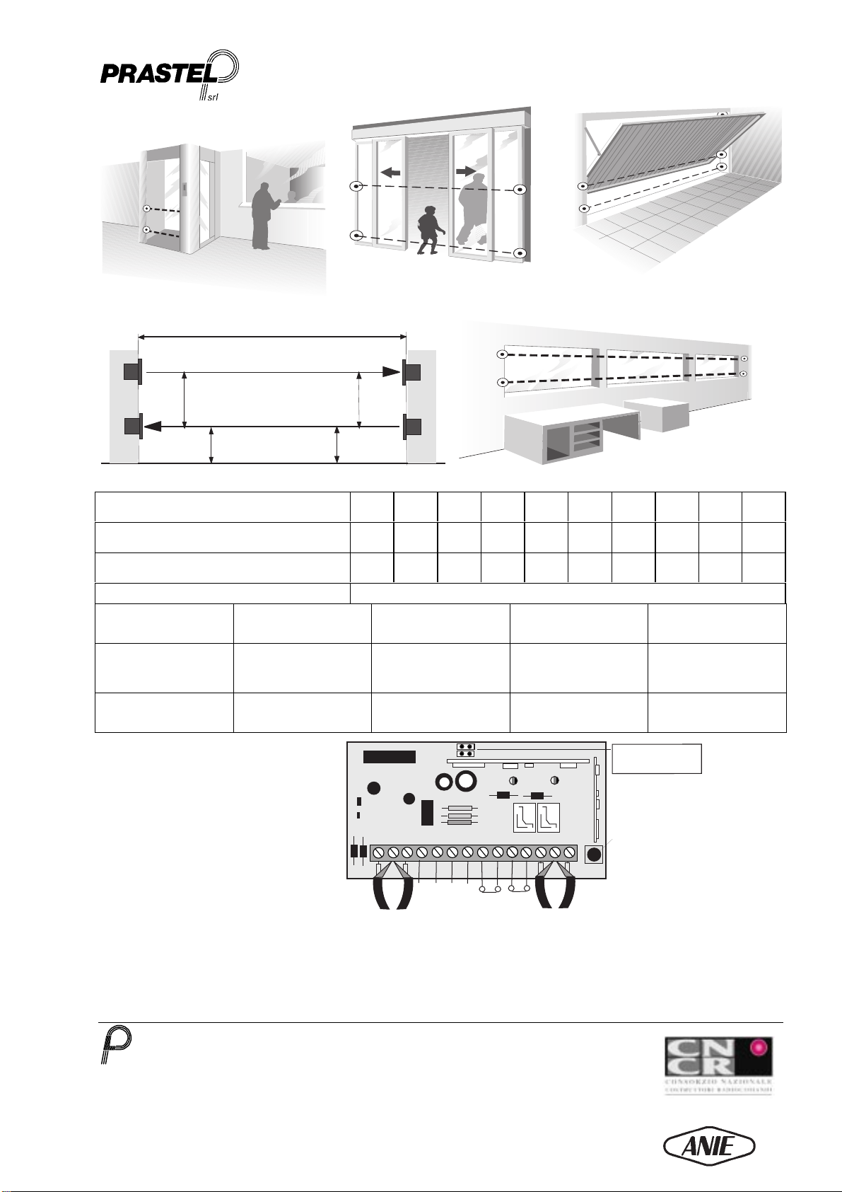
1. ALLGEMEINE BESCHREIBUNG
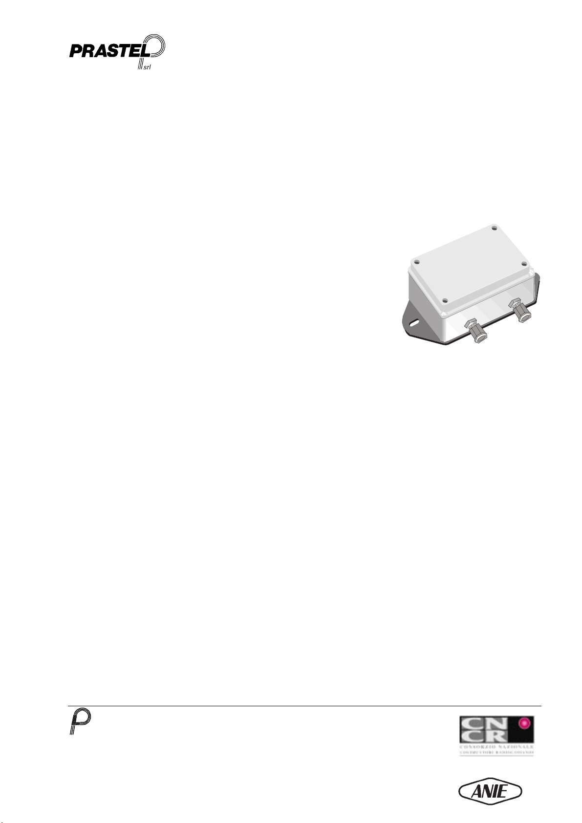
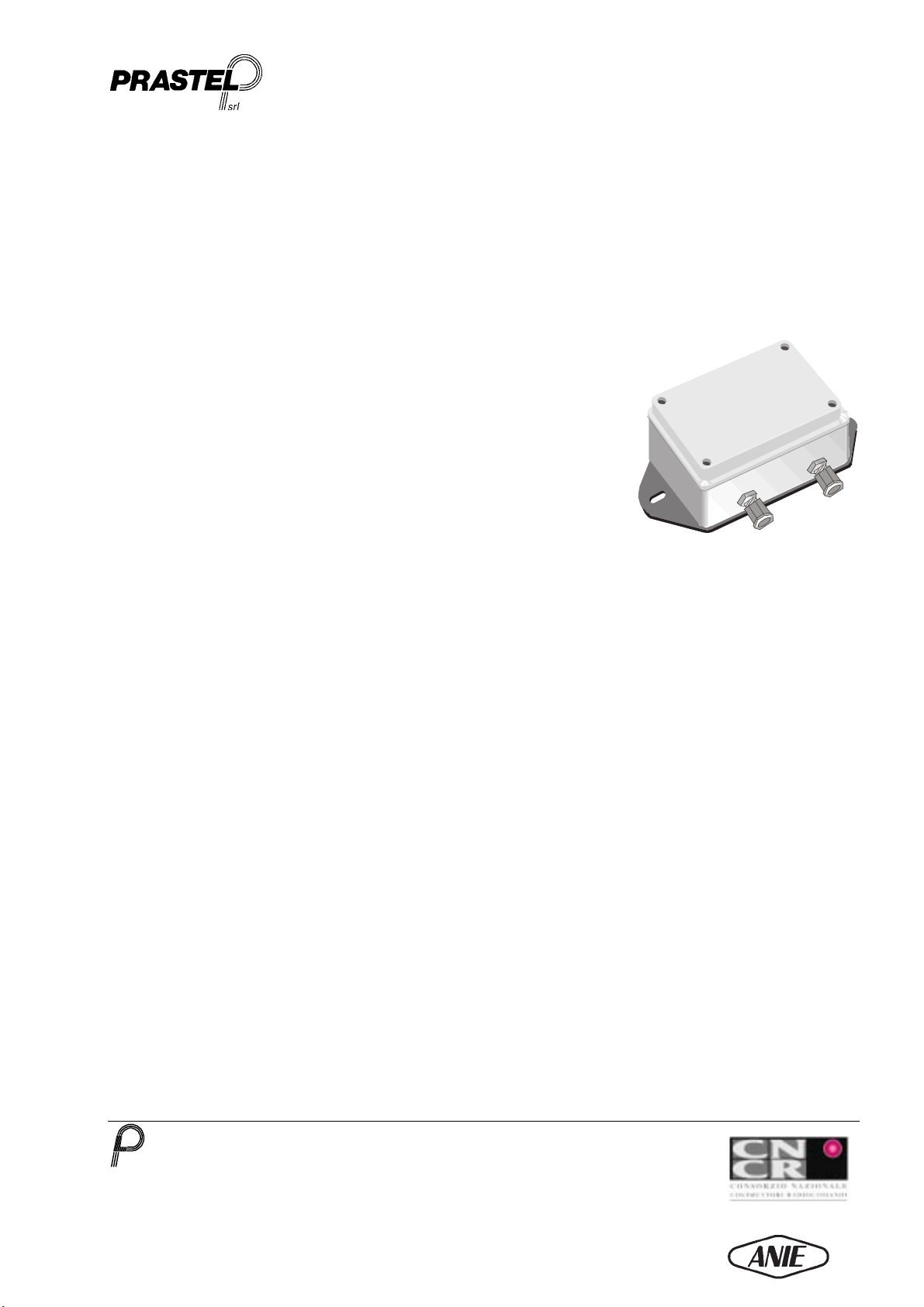
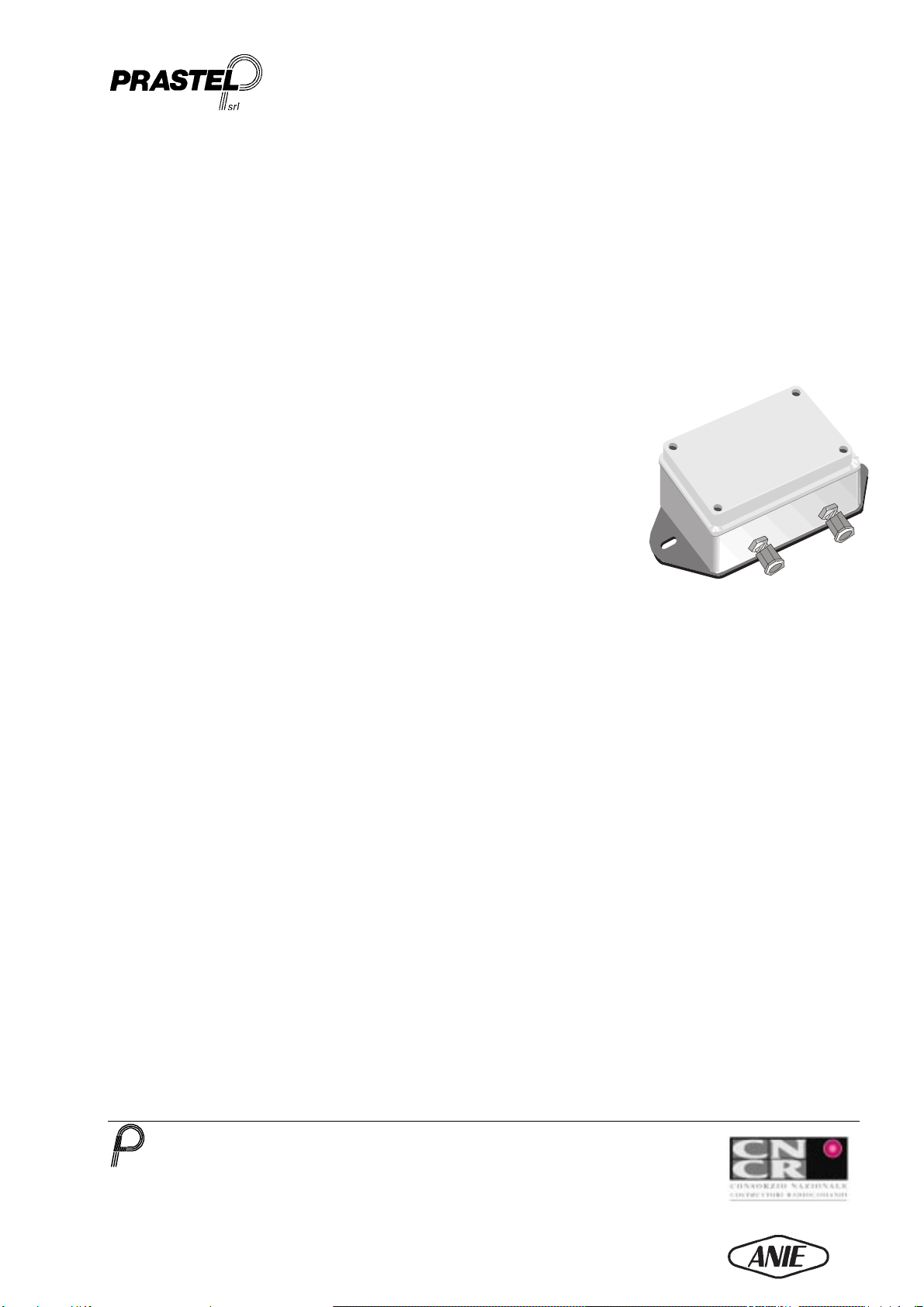
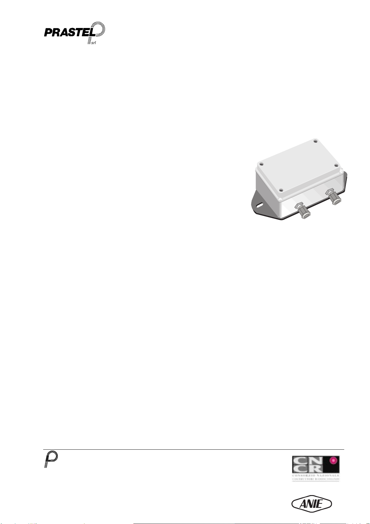
Der mit 2 unabhängigen Strahlen arbeitende Photozellenverstärker FOTOTEST/2 wurde konzipiert, entwickelt und konstruiert mit der
Zielsetzung, in Kopplung mit speziellen Sonden die höchstmögliche Sicherheit eines automatisierten Zugangs zu gewährleisten.
Beispiele: Aufzüge, Bank-Sicherheitsschleusen (Drehtür-„Hülsen“), Automatiktore, Garagentore, Industrietore usw... Kann verwendet
werden, indem die Sonden direkt auf der Durchfahrt/dem Durchgang oder auch auf einer oder mehrerer Sicherheitsflanken positioniert
werden.
Das Übereinstimmung mit den strengen europäischen Referenzstandards (EWG) liefert darüber hinaus die Garantie für Qualität und
Zuverlässigkeit des Produkts.
Die Kopplung an mit der “EG-Richtlinie 89/392/EWG” in Übereinstimmung stehende Motorsteuerzentralen (wie die Prastel-Zentralen der
Familie Euromatic) ermöglicht die Mitbenutzung der Autotest-Funktion: Mit Hilfe dieser Funktion wird der korrekte Betrieb des
Photozellen-Verstärkers beim Empfang des Autotest-Impulses kontrolliert.
2. DIE WICHTIGSTEN TECHNISCHEN EIGENSCHAFTEN
•Steuerung zweier Strahlen
•Zwei N.C.-Ausgangsrelais in Korrespondenz zu zwei unabhängigen Strahlen.
•Selbsttätiger Test („Autotest“) des korrekten Betriebs.
•Wahl des Autotest-Niveaus mittels Jumper (> 12-24 V dc oder < 5 V dc)
•Leichte Installation und einfache Zentrierung der Sonden dank der Funktion “Install Check” zur Dämpfung der Intensität der
Infrarotstrahlen.
•Kompatibel mit den Prastel-Sonden, Modelle:
CR/9MS, CR/9MS9, CR/9MSD, CR/9MSP, CR/FC, CR/20MS
•Übereinstimmung mit der Norm UNI 8612
•Übereinstimmung mit den zuständigen EG-Richtlinien:
EG-Richtlinie 89/392/EWG
EG-Richtlinie zur elektromagnetischen Verträglichkeit (EMC) 89/336/EWG
3. TECHNISCHE DATEN
Speisung 12÷24 Vac/dc ±10%
Leistungsaufnahme Max. 1 W (2 Strahlen)
Infrarotstrahlen-Wellenlänge 850 nm.
Reichweite 5 ÷ 20 m (Nennwert)
Betriebstemperatur -20 °C / +70 °C
Relais-Reaktionszeit 20 ms
Relais Rückstellzeit 0,5 s
Gewicht 520 g
4. ANSCHLUSS UND INBETRIEBSETZUNG DER ZENTRALE
•Bevor Sie mit der Installation des Photozellen-Verstärkers FOTOTEST/2 beginnen, lesen Sie bitte sorgfältig die “Allgemeinen
Sicherheitshinweise” durch.
•Fixieren Sie die Box unter Verwendung der dazu vorgesehenen Befestigungsschrauben.
•Richten Sie die Sonden aus (siehe die im Punkt 2 genannten Modelle)
•Führen Sie die Anschlusskabel über die dazu bestimmten Kabeldurchgänge.
•Schließen Sie die Versorgungs- und die Signalkabel an.
•Führen Sie Strom zu und stellen Sie sicher, dass die Strahlen-Zentrier-LEDs 1 und 2 leuchten.
•Wählen Sie mit Hilfe der Jumper J1 beziehungsweise J2 das niedrige oder hohe Autotest-Niveau (hängt von der angeschlossenen
Steuerzentrale ab).
•Drücken Sie die Taste “Install Check”: Die Intensität der angeschlossenen Strahlen wird nun um 40 % reduziert. Stellen Sie sicher,
dass während dieses Vorgangs die Zentrier-LEDs 1 und 2 stets leuchten.
•Überprüfen Sie den störungsfreien Betrieb der Autotest-Funktion, indem Sie die angeschlossene Zentrale zur Ansteuerung des
entsprechenden Impulses veranlassen (nur dann, wenn die Zentrale mit der Autotest-Funktion versehen ist). Nach der Impuls-
Ansteuerung schalten die an die Strahlen 1 und 2 gekoppelten LEDs aus und wieder ein. Gleichzeitig schalten die zugehörigen
Relais vom Status N.C. (Ruhekontakt) auf N.O. (Arbeitskontakt) und kehren anschließend in den ursprünglichen Status N.C. zurück
(nur dann, wenn die Strahlen zuvor angeschlossen und ausgerichtet worden waren).

FOTOTEST/2
PRASTEL S.r.l.
Via del Vetraio, 7 40138 Bologna Italy - Tel. +39-051-6023311 Fax +39-051-538460
E-mail: info@prastel.com - Web site: http://www.prastel.com
FOTOTEST/2 01/1999.DOC
MEMBER OF
ESPAÑOL
1. DESCRIPCIÓN GENERAL
El amplificador de fotocélula de 2 rayos independientes FOTOTEST/2 ha sido ideado, proyectado y construido con la
finalidad de garantizar, en acoplamiento con las sondas correspondientes, la máxima seguridad en un acceso
automatizado; Ej.: ascensores, puertas giratorias antirrobo, puertas automáticas, puertas de vaivén, industriales, etc..
Puede ser utilizado tanto ubicando las sondas directamente en el paso como en el interior de una o más costas de
seguridad.
Su conformidad con los rígidos estándares europeos (CE) es por demás garantía de calidad y fiabilidad del producto.
De hecho, su acoplamiento con las centrales de mando de motores conformes con la «Directiva de Máquinas
89/392/CEE» (como las centrales Prastel de la familia Euromatic), permite utilizar la función de autotest mediante la cual
se controla el correcto funcionamiento del mismo amplificador de fotocélula ante la recepción del impulso de autotest.
2. CARACTERÍSTICAS PRINCIPALES
•Gestión de dos rayos independientes
•Dos salidas de relé N.C. correspondientes a los dos rayos independientes
•Autotest de correcto funcionamiento
•Selección del nivel de autotest mediante puente (> 12-24 Vdc o bien < 5 Vdc)
•Facilidad de instalación y de alineación de las sondas gracias a la función
«Install check» de atenuación de la intensidad de los rayos infrarrojos.
•Puede ser asociado a las sondas Prastel modelos:
CR/9MS, CR/9MS9, CR/9MSD, CR/9MSP, CR/FC, CR/20MS
•Conformidad con la norma UNI 8612
Conforme a las Directivas Europeas de referencia:
Directiva de Máquinas 89/392/CEE
Compatibilidad Electromagnética (EMC) 89/336/CEE
3. CARACTERÍSTICAS TÉCNICAS
Alimentación
12÷24 Vac/dc ±10% (programable)
Potencia absorbida
Máx. 1 W (2 rayos)
Longitud de onda R.I.
850 nm.
Alcance
5 ÷ 20 m nominales
Temperatura de funcionamiento
-20 °C / +70 °C
Tiempo de intervención del relé
20 ms
Tiempo de restablecimiento
0,5 s
Peso
520 g
4. CONEXIÓN Y PUESTA EN SERVICIO DE LA CENTRAL
•Antes de proceder a la instalación del amplificador de fotocélula FOTOTEST/2, leer las «Advertencias Generales
Para la Seguridad».
•Fijar el box mediante los respectivos orificios de fijación.
•Alinear las sondas (véase los modelos citados en el punto 2).
•Hacer pasar los cables de conexión por los pasacables respectivos.
•Conectar los cables de alimentación y de señal.
•Alimentar y verificar que los LEDS 1 y 2 de alineación de los rayos estén encendidos.
•Seleccionar mediante los jumpers J1 o J2 el nivel de autotest bajo o alto (depende de la central de mando
conectada).
•Presionar el botón de «Install check», la intensidad de los rayos conectados es reducida en un 40 %. Durante esta
operación, asegurarse que los LEDS 1 y 2 permanezcan encendidos.
Verificar el correcto funcionamiento de la función de autotest haciendo ejecutar el mando a la central conectada (sólo
si la central está predispuesta para la función de autotest). Después de dicho mando, los LEDS asociados a los
rayos 1 y 2 se apagan, se volverán a encender y al mismo tiempo conmutarán los respectivos relés del estado N.C.
al estado N.A., para luego regresar al estado inicial de N.C. (sólo si los rayos habían sido previamente conectados y
alineados).

FOTOTEST/2
PRASTEL S.r.l.
Via del Vetraio, 7 40138 Bologna Italy - Tel. +39-051-6023311 Fax +39-051-538460
E-mail: info@prastel.com - Web site: http://www.prastel.com
FOTOTEST/2 01/1999.DOC
MEMBER OF
TX
RX TX
RX
TX RX
TX
RX
TX
TX
RX
RX
H2 H2
H1
H1
CR9/MS
TX
RX
RX
TX
L1
TX
TX
RX
RX
L1= Distanza installazione (Portata)
L1= Distancia de instalación (Alcance) 1m2m3m4m5m6m7m8m9m10m
H2= Distanza min. verticale tra gli optosensori TX/RX
H2= Distancia vertical mínima entre los optosensores TX/RX 14 cm 28 cm 42 cm 56 cm 70 cm 84 cm 98 cm 112 cm 126 cm 140 cm
H1= Distanza min. da terra degli optosensori TX/RX
H1= Distancia mínima de los optosensores TX/RX a partir del
suelo 7 cm 14 cm 21 cm 28 cm 35 cm 42 cm 49 cm 56 cm 63 cm 70 cm
Errore max. disallineamento
Error máximo de desalineación ±2°
Distanza minima dei raggi se
installati nella stessa direzione in
funzione della distanza
d’installazione
Minimun beam distance if
installed in the same direction,
based on the installation distance.
Distance minimun des rayons,
s’ils sont montès dans la mème
direction, en fonction de la
distance d’installation
Mindestabstand der Strahlen wenn,
diese in gleicher Richtung installiert
sind. Hängt von der Installations-
Entfernung ab
Distancia mínima entre los rayos
cuando están instalados en la
misma dirección, en función de la
distancia de instalación.
Con raggi invertiti (Fig.4) la
distanza minima tra i raggi è di 5
cm (valido per tutte le portate).
With the beams reversed (Fig. 4),
the minimun distance between
the beams is 5 cm (valid for all
ranges).
Avec les rayons inversès (Fig. 4)
la distance minimun entre les
rayons est 5 cm (valable pour
toutes les portées).
Mit invertiertem Lichtstrahl (Abb. 4)
ist der Mindestabstand 5 cm (gültig
für alle Reichweiten).
Cuando los dos rayos están
invertidos (Fig. 5) la distancia
mínima entre los mismos es de 5
cm. (válido para todos los
alcances).
Per portate maggiori di 4 m , si
consiglia d’installare gli opto-
sensori TX/RX invertiti (Fig.4)
For ranges greater than 4 m , we
recommend installing the TX/RX
optic sensors reversed (Fig. 4).
Pour des portées dépassant 4m,
il est conseillé d’installer les
capteurs optiques TX/RX inversés
(Fig. 4).
Für Reichweiten über 4 m wird
empfohlen, die Optosensoren TX/RX
umgekehrt zu installieren (Abb. 5).
Recomendamos instalar los
optosensores TX/RX invertidos
(Fig. 5)
1 2 3 4 5 6 7 8 9 10 11 12 13 14
J 1
J 2
LED
TX/RX 1
B
TEST
J1 = TEST >12-24 Vdc
J2 = TEST < 5 Vdc
Raggi RX
(centrale bianco)
TX beams
(central white)
2
1
Raggi TX
(centrale rosso)
TX beams
(central red)
12
+
~-
~
Alimentazione
Power supply
12-24 Vac/dc
(6) AUTOTEST
<5 Vdc - >12/24 Vdc
(7) Schermo esterno
(7) External screen
(8-9) N.C. TX/RX 1
LED
TX/RX 2
(10-11) N.C. TX/RX 2
Pulsante per verifica
installazione
Install check button
Fig. 1 Fig. 2 Fig. 3
Fig. 4 Fig. 5
Table of contents
Languages:
Other PRASTEL Security Sensor manuals