GF U1000 V2 User manual

User Manual
U1000 V2 Ultrasonic Flowmeter
U1000 V2 HM Ultrasonic Heatmeter
GF Piping Systems
U1000
4-20mA
PULSE
Enter Pipe ID :
050.0 mm

Instruction Manual
2
Original instruction manual
Follow the instruction manual
The instruction manual is part of the product and is an important element of the safety concept.
• Read and follow the instruction manual.
• Always keep the instruction manual available at the product.
• Pass on the instruction manual to all subsequent users of the product.
Contents
1 Intended use....................................................................................................................................................4
2 About this document......................................................................................................................................4
2.1 Warnings .................................................................................................................................................4
2.2 Other related documents.....................................................................................................................4
2.3 Abbreviations.........................................................................................................................................5
3 Safety and responsibility ..............................................................................................................................5
4 Transport and storage...................................................................................................................................5
5 Design and function .......................................................................................................................................6
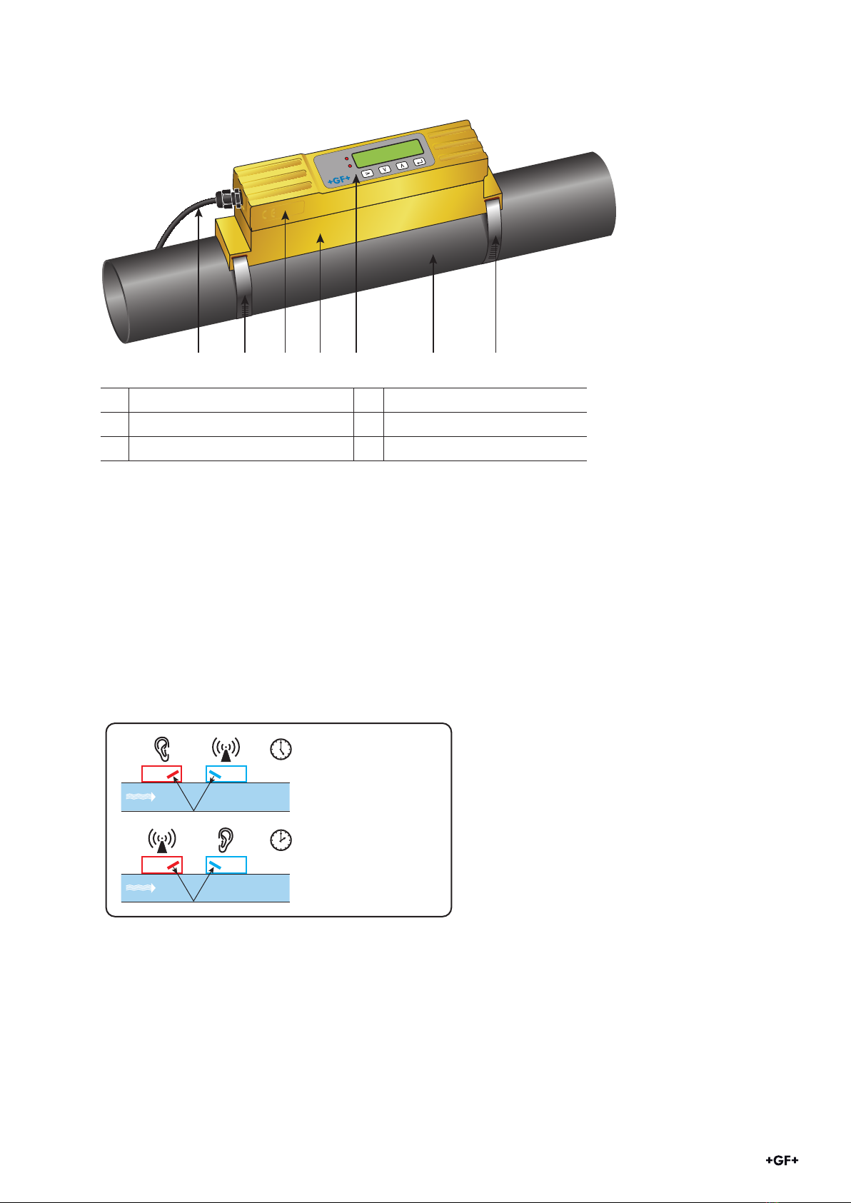
5.1 Design......................................................................................................................................................6
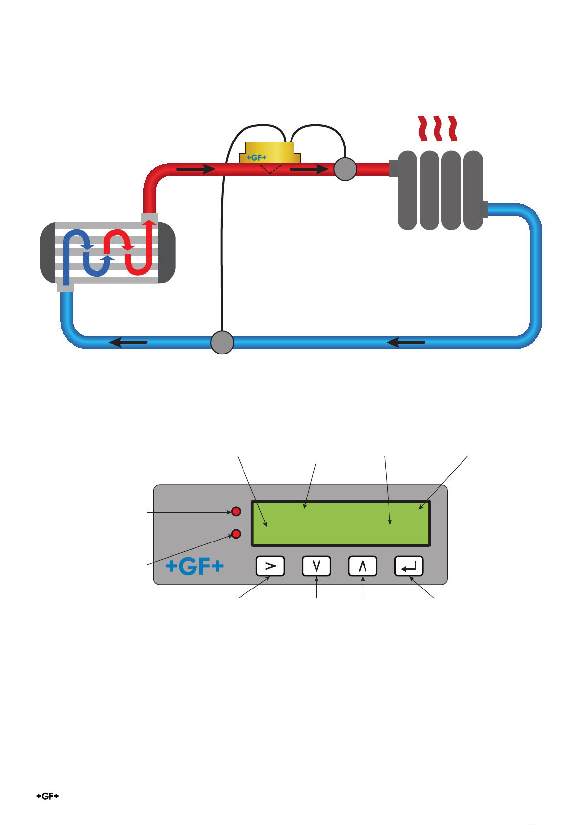
5.2 Principle of operation ...........................................................................................................................6
5.3 User Interface ........................................................................................................................................7
6 Scope of delivery ............................................................................................................................................8
7 Installation ......................................................................................................................................................8
7.1 Identify suitable location for flow measurement............................................................................8
7.2 Identify suitable location for temperature measurement (HM versions only) ..........................9
7.3 Pipe mounting surface preparation...................................................................................................9
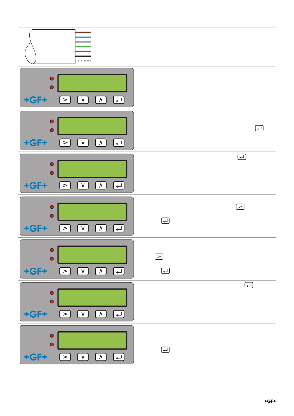
7.4 Start-Up...................................................................................................................................................10
7.5 Adjusting the sensor distance ............................................................................................................11
7.6 Mounting the GF U1000 V2 on the pipe.............................................................................................12
7.6.1 Selecting the pipe adapter........................................................................................................12
7.6.2 Applying gel pads.......................................................................................................................13
7.6.3 Mounting the guide rail..............................................................................................................13
7.6.4 Removing sensor-holding screws ..........................................................................................14
7.6.5 Connecting the electronics module ........................................................................................14
7.7 Moving the guide rail ............................................................................................................................15
7.8 Attach the temperature sensors (HM versions only)......................................................................15
8 Electrical connection & outputs...................................................................................................................16
8.1 4-20 mA, Pulse option (not for HM versions)...................................................................................16
8.1.1 Interface cable ............................................................................................................................16
8.2 Pulse output ...........................................................................................................................................17
8.2.1 Volumetric pulses.......................................................................................................................17
8.2.2 Frequency mode.........................................................................................................................18
8.2.3 Energy pulse (HM versions only).............................................................................................18
8.2.4 Flow alarm – low flow...............................................................................................................18
8.2.5 Flow alarm – signal loss...........................................................................................................18
8.3 Current / 4-20 mA Output....................................................................................................................18
8.4 Modbus option........................................................................................................................................19
8.4.1 Interface cable ............................................................................................................................19
8.4.2 Modbus connections at device.................................................................................................20
8.4.3 Modbus wiring diagramm.........................................................................................................20
8.4.4 Modbus registers........................................................................................................................22
8.5 Temperature probes (HM versions only)..........................................................................................24

Instruction Manual
3
9 Password-protected menus.........................................................................................................................24
9.1 Overview .................................................................................................................................................24
9.2 Opening a password-protected menu...............................................................................................25
9.3 Changing the selection in menus .......................................................................................................25
9.4 Changing the numerical values in data menus ...............................................................................26
9.5 Accessing the password-protected menu........................................................................................27
9.6 Setup........................................................................................................................................................27
9.7 Current output menu (4-20 mA versions only)................................................................................29
9.8 Modbus setup menu (Modbus versions only) ..................................................................................29
9.9 Pulse output menu................................................................................................................................30
9.9.1 Volume pulse...............................................................................................................................30
9.9.2 Flow alarm...................................................................................................................................30
9.9.3 Energy Pulse (HM versions only).............................................................................................31
9.9.4 Frequency ....................................................................................................................................31
9.10 Calibration menu ..................................................................................................................................31
9.11 Volume totals menu .............................................................................................................................32
9.12 Diagnostics menu .................................................................................................................................33
10 Maintenance & limitations ............................................................................................................................34
10.1 Maintenance plan .................................................................................................................................34
10.2 Limitations with Water-Glycol Mixtures...........................................................................................34
11 Troubleshooting..............................................................................................................................................35
11.1 Troubleshooting the flow reading .....................................................................................................35
11.2 Error messages ....................................................................................................................................35
11.3 Example error messages....................................................................................................................36
11.4 Modbus Error Messages .....................................................................................................................36
11.5 Flow errors ............................................................................................................................................36
11.6 Flow warnings.......................................................................................................................................36
11.7 Data entry errors..................................................................................................................................37
12 Removal............................................................................................................................................................37
13 Specifications..................................................................................................................................................38
13.1 Default values........................................................................................................................................39
14 Disposal............................................................................................................................................................40

Instruction Manual
4
WARNING!
Risk of fatal or serious injury!
There is a risk of fatal or serious physical injury if warnings are ignored!
CAUTION
Danger of minor physical injury!
Failure to pay attention to these warnings will lead to a risk of physical injury!
2 About this document
This document contains all the information necessary for installation, operation and maintenance of the
product.
2.1 Warnings
This instruction manual contains warning notices that alert you to the possibility of injuries or damage to
property. Always read and pay attention to these warnings!
NOTICE
Risk of damage to property!
Failure to comply leads to a risk of damage to property (loss of time, loss of data, device fault etc.)!
Other symbols
Symbol Meaning
1. Actions required in a numbered sequence.
►Actions required
•Listing of items on various levels
Intended use
The GF U1000 V2 ultrasonic flowmeter is used to obtain an optimal measurement of the volume flow and flow
rate in steel and plastic pipes with outside diameter from 22 mm (0.86”) to 180 mm (7”). Measurable pipe sizes
are dependent on pipe material and inner pipe diameter.
The GF U1000 V2 HM is an ultrasonic heatmeter, also BTU-meter, energy meter or thermal meter. It uses
ultrasonic sensors to obtain a measurement of the volume flow and flow rate and is equipped with PT100 to
measure flow and return temperatures.
From the measured flow and temperature values, the GF U1000 V2 HM calculates energy rate and totalized
energy.
Typical applications
• Hot water metering and flow measurement
• Flow measurement and heat measurement
• Cold water metering and flow measurement
• Tap water metering and flow measurement
• Service water metering and flow measurement
• High-purity water metering and flow measurement

Instruction Manual
5
Abbreviation Description
ABS Acrylonitrile-butadiene-styrene
DA Double acting function
EMC Electromagnetic Compatibility
FC Fail safe to close function
FO Fail safe to open function
LCD Liquid crystal display
LED Light-emitting diode
MOSFET Metal oxide semiconductor field eect transistor
PB-INSTAFLEX Polybutene plastic piping system
PE-ELGEF Polyethylene plastic piping system
PP-PROGEF Polypropylene plastic piping system
PVDF-SGEF PVDF (polyvinylidene fluoride) plastic piping system
SPNO MOSFET Single-pole normally open metal oxide semiconductor field eect transistor
VC-U-PVC Polyvinyl chloride
2.3 Abbreviations
3 Safety and responsibility
►Only use the product for the intended purpose, see Intended Use.
►Do not use any damaged or faulty product. Sort out any damaged product immediately.
►Make sure that the piping system has been installed professionally and that it is inspected
regularly.
►Have the product and accessories installed only by persons who have the required training,
knowledge or experience.
►Regularly train personnel on all questions regarding the locally regulations applying to
occupational safety and environmental protection, especially for pressurised pipelines.
4 Transport and storage
►Protect the product against external forces during transport (impacts, knocks, vibrations etc.).
►Transport and / or store the product unopened in its original packaging.
►Protect the product from dust, dirt, moisture as well as heat and ultraviolet radiation.
►Ensure that the product is not damaged either by mechanical or thermal influences.
►Before assembling, check the product for damage during transport.
2.2 Other related documents
• Georg Fischer industrial planning fundamentals
These documents are available through agents of GF Piping Systems or at www.gfps.com.

Instruction Manual
6
1 Power supply (AC/DC) 4 Guide rail
2 Pipe clamp 5 User interface
3 Electronics module 6 Pipe
The GF U1000 V2 consists of an electronics module (3) and a guide rail (4), which together form a
single unit which is fixed to the pipe (6) by pipe clamps (2).
The GF U1000 V2 is supplied with power through an external 12 – 24 V power adapter (1).
5.2 Principle of operation
The GF U1000 V2 takes accurate flow measurements by determining the dierence between the
transmission times of two ultrasonic signals.
U1000
4-20mA
PULSE
Enter Pipe ID :
050.0 mm
1234 5 6 2
5 Design and function
5.1 Design
=
=
T1
T2
T1-T2=m/s
}
Principle of Operation
A periodic voltage pulse acts on the transducer crystals and produces an ultrasonic beam at a certain
frequency. The beam is first transmitted by the downstream transducer (blue) to the upstream
transducer (red).
The beam is then sent in the opposite direction, i.e. from the upstream transducer (red) to the
downstream transducer (blue). The time taken for the ultrasonic to pass through the liquid in this
direction is slightly shortened by the speed at which the liquid flows through the pipe.
The resulting time dierence T1 – T2 is directly proportional to the speed at which the liquid flows
through the pipe.

Instruction Manual
7
In addition to the flow rate, the GF U1000 V2 HM models measure the temperature dierence
between the flow and return of the system via two Pt100 temperature sensors.
The dierence in temperature between the flow and the return, in combination with the volume of
water that has passed through the system, is used to calculate the energy dierence in the medium.
°C
°C
Flow Sensor
Temp. Sensor
Temp. Sensor
Heated / cooled object
Heat exchanging device
Flow pipe
Return pipe
5.3 User Interface
U1000
4-20mA
PULSE
Sig: 44% *
0727.6 1/min
Energy
(Heat Meter versions)
Energy pulse signal
4 to 20 mA
(Flow Meter versions)
4 to 20 mA signal
Pulse
Illuminated when the
Pulse, Frequency or
Alarm functions are
enabled
Select
Selection key.
Choose between
options on the
display.
Decrease/Down
Decrement the
value of each
digital in numeric
entry fields.
Enter
Enter displayed
selection/terminate
the data entry.
Select menu or
exit to Flow Reading
Screen.
Increase/Up
Increase the
value of each
digital in numeric
entry fields.
Flow
Measured
flow.
Signal strength
For accurate
results, must be
over 40%.
Flow Direction
* Indicates positive flow
! Indicates reversed flow
Flow Units
Units applicable
to measured flow.

Instruction Manual
8
6 Scope of delivery
Component Pcs.
GF U1000 V2 electronics module 1
Guide rail 1
Gel-Pads 4
Pipe clamps 2
Cable 1
Adapter for small pipes < 40 mm 1
Adapter for small pipes < 60 mm 1
Modbus cable (Modbus version only) 1
PT100 temperature sensor with 3 meter cable (HM version only) 2
Stainless cable tie for PT100 temperature sensors (HM version only) 2
7 Installation
7.1 Identify suitable location for flow measurement
The GF U1000 V2 requires an even and uniform flow profile, since distortions in the flow can cause
unpredictable measurement errors.
In many applications, however, it is not possible to have a uniform flow rate through 360°. This may
be, for example, because there are air bubbles inside the top of the pipe, or turbulence in the pipe, or
sludge at the bottom of the pipe.
Experience has shown that the most accurate results are obtained if the guide rail of the
transducers is not mounted vertically to the pipe, but turned at an angle of about 45° to the right
or left on the pipe.
Possible air gap
Possible deposits
(sludge)
Possible sensor position
Flow
Turbulent flow profile Laminar flow profile
10x inner diameter
5x inner diameter

Instruction Manual
9
NOTICE
Incorrect Measurements
Measurements can be distorted if the transducers are positioned close to upstream pipe components
and fittings such as pipe bends, T-branches, valves, pumps and similar obstacles.
To ensure the GF1000 V2 is positioned at a place that has an undistorted flow profile, the transducers
must be mounted suciently far from possible sources of distortion to prevent these from having
any eect on the measurement.
• Install a straight section of pipe with length 10 times the diameter on the upstream side of the
transducer.
• Install a pipe section with length 5 times the diameter on the downstream side of the transducer.
In exceptional cases, a pipe with length 5 times the diameter may be sucient.
7.2 Identify suitable location for temperature measurement (HM versions only)
For optimum reliability on boiler applications, the flow measurement needs to be made on the cold
side of the system. For optimum reliability in chiller applications, the flow measurement needs to be
made on the warmer side of the system.
7.3 Pipe mounting surface preparation
►Before attaching the transducers, make sure that desired position meets the distance
requirements.
See Section 8.1 .
►Clean the pipe to remove any grease residues.
►Remove any dirt and flaking paint in order to ensure an even surface.
NOTICE
Maximum accuracy
A smooth and even contact between pipe surface and transducer is an important factor for obtaining
a suciently strong ultrasonic signal.
Flow
Hot
Cold
Return
Heat Energy
Consumer
U1000MkII-HM
Combined Flow and Heat Meter
Temperature Sensor
Hot Flow
Temperature Sensor
Cold Return

Instruction Manual
10
7.4 Start-Up
1
2
3
4
5
6
7
12v / 24V input
12v / 24V return conductor
Pulse +
Pulse -
Output (+), 4 to 20 mA
Return (-), 4 to 20 mA
Non-insulated shielding
►Connect the GF U1000 V2 to power supply
See section 9 Electrical connection for further
details.
4-20mA
PULSE
+GF+
000000 02/19
►The GF U1000 V2 boots for the first time.
The GF start screen is displayed for 5 s.
4-20mA
PULSE
Enter Pipe ID :
050.0 mm
►The start-up wizard automatically starts.
Enter pipe id menu appears.
►Select your pipe inside diameter and press to
acknowledge.
See Section 1, Page 31 for more details.
4-20mA
PULSE
Pipe Material :
PVC-U / PVC-C
►Select your pipe material and press to
acknowledge.
4-20mA
PULSE
Instrument Type :
Heating / Chiller
HM versions only:
►Select the instrument setting using .
►The unit is preconfigured for Heating applications.
►Press to confirm the setting.
4-20mA
PULSE
Instrument Side :
Return / Flow
HM versions only:
►Select which side the electronics unit is installed
using .
►The unit is preconfigured for Return.
►Press to confirm the setting.
4-20mA
PULSE
Instrument Fluid :
Glycol / Water
►Select your instrument fluid and press to
acknowledge.
4-20mA
PULSE
Set Temperature :
Hot / Cold
►Select you media temperature:
- ‘Cold’ for temperature 2 °C to 40 °C
- ‘Hot’ for temperature 40 °C to 85 °C
►Press to acknowledge.

Instruction Manual
11
7.5 Adjusting the sensor distance
NOTICE
Maximum accuracy
The two sensors must be placed at defined distance relative to each other, where the distance
depends on the pipe inside diameter and pipe material.
NOTICE
If the power supply is switched o and then on again after the pipe inside diameter is entered for the
first time, then the last applied configuration is used.
If the configuration is changed for some reason, the password-protected menu must be used.
See Section 10 Password-protected menus.
4-20mA
PULSE
Set Separation :
B-4
►The GF U1000 V2 shows you the correct
transducer distance for your application.
►Press to acknowledge
►Proceed with 8.5 Adjusting the sensor distance
4-20mA
PULSE
Checking Signals :
Searching. . .
The GF U1000 V2 searches for a valid signal.
4-20mA
PULSE
Sig : 98% *
0260.8 l/min
4-20mA
PULSE
Sig : 98% !
0260.8 l/min
If a valid signal is detected, the signal strength and
flow are displayed.
The direction of flow at switch-on time is taken as a
positive flow value and the current and pulse output
refer to this flow direction.
If the flow direction is reversed, the volume flow is
still displayed. The activity indicator changes from
a star to an exclamation mark, no more pulses
are generated and the 4 to 20 mA current output
changes to a 3.5 mA alarm status.
4-20mA
PULSE
Sig : 00%
– – – – – l/min
If the GF U1000 V2 does not detect a valid signal ‘Sig:
00%’ is shown.
In this case please make sure you followed the steps
in section 8.5 Adjusting the sensor distance and 8.6
Mounting the GF U1000 V2 on the pipe correctly.
See also section 12 Troubleshooting for further advice.

Instruction Manual
12
► Move the sensors to the optimal position (see start-up wizard in section 8.4 Start-Up).
►With the flow sensors in the correct positions, tighten the sensor-holding screws so that the
sensors are secure.Tighten the sensor mounting screws.
7.6 Mounting the U1000GF U1000 V2 on the pipe
7.6.1 Selecting the pipe adapter
Two adapters are available for attaching the measuring device to pipes with an outside diameter of ≤
60 mm.
NOTICE
If these adapters are not necessary, store them away for a possible later change of position.
►Define optimal sensor distance with entering your pipe credentials in the GF U1000 V2
start-up wizard (see section 8.4 Start-Up). (E.g. B-4 for PVC-U pipe with 50 mm inside
diameter)
►Loosen the sensor mounting screws, suciently to loosen the flow sensors and allow
sideways movement. DO NOT fully unfasten or remove the screws at this stage.
►Move the sensors to the optimal position (see start-up wizard in section 8.4 Start-Up).
G F E D C B A
1 2 3 4 5
Lower enough for
sideways movement
G F E D C B A
1 2 3 4 5

Instruction Manual
13
7.6.2 Applying gel pads
1. Apply two a gel pads centrally onto the base of each of the two flow sensors.
2. Remove the gel pad covers.
3. Ensure there are no air bubbles between each pad and sensor base.
7.6.3 Mounting the guide rail
►Using the hose clips provided, clamp the Sensor Assembly (and adaptors if needed, see
section 8.6.1 Selecting the pipe adapter) to the pipe at an angle of 45° to the top of the pipe.
Experience has shown that the most consistently accurate results are achieved when the unit
is mounted at this angle (see 8.1 Identify suitable location for flow measurement). This mini-
mises the eect of any flow turbulence resulting from entrained air along the top of the pipe
and sludge at the bottom.
Air
Sludge
45°
G F E D C B A
1 2 3 4 5
Outside diameter less than
40 mm
Outside diameter
40 mm – 60 mm
Outside diameter more than
60 mm
Top and bottom pipe
adapters (black) Top pipe adapter (black) No pipe adapter
B34

Instruction Manual
14
7.6.4 Removing sensor-holding screws
►Mount the guide rail (1) and pipe adapters if necessary (see section 8.6.1 Selecting the pipe
adapter) on the pipe (3) using the pipe clamps (2).
►Loosen the mounting screws and remove along with the washers.Release and remove the
sensor-holding screws. The flow sensors are spring-loaded to ensure good contact with the
pipe surface.
NOTICE
When the sensors have been moved to the correct setting and the guide rail is attached to the pipe
REMOVE the sensor mounting screws, which will allow the spring loaded transducers to make con-
tact with the pipe.
Store the mounting screws and washers away for future maintenance work or for a possible change
of position later.
7.6.5 Install Connecting the electronics module
► Ensure that the power is switched o.
►Connect the Electronics Module (wired as described in section 9 Electrical connection). The
two leads can be connected either way round.
NOTICE
Do not clip the electronics module onto the sensor assembly until you have checked operation.
G F E D C B A
1 2 3 4 5
G F E D C B A
1 2 3 4 5

Instruction Manual
15
7.7 Moving the guide rail
If it becomes necessary to change the position of the guide rail or the sensors:
►Remove complete assembly from the pipe.
►Undo the screw at the end of the guide rail and gently lift the same end as shown.
► The opposite end of the electronics can now be released from the guide rail.
► Disconnect the sensors.
► Remove the original Gel pads from the sensors.
► Push the sensor blocks into the guide rail so that the washers and locking screws can be
refitted.
► Place replacement Gel pads down the centre of the sensor block.
► Follow the procedure in section 8.6 Mounting the GF U1000 V2 on the pipe for re-installing the
guide rail on the pipe.
7.8 Attach the temperature sensors (U1000 V2 HM versions only)
CAUTION
The temperature sensors must be balanced before initial use, using the procedure described
below and used with the cable length supplied. Extending or shortening the cables will negate the
calibration of the sensors.
The temperature sensors must be located at the input and output of the system that has to be mon-
itored. The area of pipe where they have to be attached must be free of grease and any insulating
material. It is recommended that any coating on the pipe is removed, so that the sensor has the best
possible thermal contact with the pipe.
The connection sockets on the Electronics Module are marked “Hot” and “Cold”. This defines the
specified position of the temperature sensors in the piping system.
MODBUS/M-BUS COLD HOT
2 3 4 5
MODBUS/M-BUS

Instruction Manual
16
To ensure an accurate temperature dierential measurement:
1. Plug the temperature sensors into the Electronics Module and place them touching each other
for 1 minute.
2. Enter the password controlled menu and scroll to the Calibration sub-menu (see chapter
“Password-protected menus”).
3. Press the Enter key until the Zero Temp Oset screen is displayed.
4. Select Yes and press the Enter key to display the “Attach Sensors” screen.
5. Press the Enter key again and wait for instrument to return to the Zero Temp Oset screen.
6. Switch o the power to the Electronics Module.
6. Complete the installation of the temperature sensors to the pipes. The temperature sensors
have a cut out profile to locate them; Use the supplied cable ties to anchor them to the pipes.
The cable ties must not be tightened too much, otherwise the sensors can be damaged. If the
sensors are located under pipe-lagging then ensure this does not put a strain on the sensor
cables.
7. Tie down the sensor cables.
8 Electrical Connection and Outputs
NOTICE
The U1000GF U1000 V2 operates in the voltage range 12 – 24 V (AC/DC). The power supply must have
a minimum rating of 7 VA per instrument. To fully meet the requirements of EMC regulations, a 12 V
connection is recommended for domestic and light industrial applications.
For full immunity to electrical interference the screen of the power/pulse output cable and modbus
cable should be connected to Earth.
For safety, connecting the U1000GF U1000 V2 to a power supply via a mains rated transformer is the
responsibility of the installer to conform to the regional voltage safety directives.
Connect the external power supply to the Brown and Blue wires of the six-core cable.
8.1 4-20 mA, Pulse option (not for HM versions)
► Connect the external power supply to the Brown and Blue wires of the six-core cable.
► Connect the White and Green wires to Pulse and the Red and Black wires to 4-20 mA input.
8.1.1 Interface cable
The GF U1000 V2 6-wire interface cable
1
2
3
4
5
6
7

Instruction Manual
17
1 12 V / 24 V input (brown)
2 12 V / 24 V return conductor (blue)
3 Pulse + (white) The SPNO MOSFET relay in the electronics module
supplies an insulated switching signal for a switchable
current of up to 500 mA and a voltage of up to 48 VAC.
This relay also provides 2500 V insulation. Galvanically
speaking, it is a volt free output.
4 Pulse - (green)
5 Output (+), 4 – 20 mA (red) The 4 - 20 mA current output is an insulated current
source designed for loads of < 620 Ω.
6 Return conductor (-), 4 - 20 mA
(black)
7 Non-insulated shielding
WARNING
Electric shock due to short-current!
Before connecting the GF U1000 V2 to an external power supply, make sure that the power supply is
switched o.
8.2 Pulse output
The isolated pulse output is provided by a SPNO/SPNC MOSFET relay which has a maximum load
current of 500mA and maximum load voltage of 48V AC. The relay also provides 2500V isolation,
between the sensor’s electronics and the outside world.
The pulse output is available at the White and Green wires. Electrically this is a volt, or potential free
contact, and when selected as a low flow alarm is configurable NO/NC.
The pulse output can be set up to operate one of five modes:
• Volumetric
• Energy (HM version only)
• Frequency
• Low Flow Alarm
• Loss of Flow (Signal) Alarm
The Alarm functions allow you to set the alarm switch to Normally Open or Normally Closed.
8.2.1 Volumetric pulses
The GF U1000 V2 default pulse width is set to 50ms which represents half of one pulse cycle. A 50ms
pulse width is required for most mechanical counters.
0 50
100
150 200 250 300 350
Time (milliseconds)
Pulse Width
50 milliseconds
Pulse output
switch open
Pulse output
switch closed

Instruction Manual
18
Formula to obtain Volume per Pulse based on a (default) 50ms pulse width:
Volume per Pulse >= maximum flow rate (in litres per minute) / 600
Example for maximum flow rate of 500 l/min:
Volume per Pulse >= 500 l/min / 600 = 0.833 litres per pulse
Rounding up to nearest whole litre: Set Volume per Pulse to 1 litre.
• After a measured volume of 10 l (preset value), a pulse is sent => 1 pulse/10 l.
• The maximum number of pulses that can be sent without storing is calculated using the two
default parameters Vol per pulse =1 and Pulse width = 50 ms, with the formula 1/(0.025x2)
giving a value of 20 pulses/s.
• If the volume flow in the pipe is so high that more than 20 pulses/s are generated, a pulse
overload error may occur if the number of stored pulses exceed a value of 1,000.
8.2.2 Frequency mode
In Frequency mode, the output frequency is proportional to the flow rate within a specified frequency
range of 1 – 200Hz.
8.2.3 Energy pulse (HM versions only)
When the Pulse Output is set to Energy, the kWh LED will be permanently illuminated. Choose from
1, 10,100kWh or 1MWh when in metric mode and 1, 10,100kBTU or 1MBTU in imperial mode. Each
pulse represents an amount of energy e.g. 1kWh. The same limitation on maximum pulse rate applies
as detailed in the Volumetric Mode. Again, a larger unit of energy per pulse or a smaller pulse width
may be required.
8.2.4 Flow alarm – low flow
For the Low Alarm the user can set a range between 0 and 9999 (no decimal places), in the same
units being used to measure flow. The default setting is normally open, but the user can select
between N/O and N/C. There is a 2.5% hysteresis on the switching of the output. Once the low flow
alarm is activated, the flow rate must rise by 2.5% more than the set value to deactivate the alarm
again.
8.2.5 Flow alarm – signal loss
If the flow reading (signal) is lost, as indicated by the flow rate being displayed as “-----“, the alarm
will be triggered. The default setting is normally open, but the user can select between N/O and N/C.
8.3 Current / 4-20 mA Output
The isolated 4-20mA is a current source and can drive into a maximum load of 620Ω.
The 4-20mA current output is available at the Red and Black wires.
The alarm current due to a flow outside the range specified or due to a loss of signal is set at 3.5mA.

Instruction Manual
19
8.4 Modbus option
The Modbus RTU interface is configured via the Modbus sub menu in the password controlled menu.
• The data rate can be selected in the range 1200 to 38400 baud.
• The address can be set in the range 1 to 126.
• Polling Rate 1000ms (1sec). Time out after 5 seconds.
• The instrument responds to the “read holding registers” request (CMD 03).
• If the flow reading is invalid then the flow value will be zero.
• If a temperature sensor goes out of range then the value will go to -11 °C (12.2 °F).
• Float byte order –AB CD – Big endian – MSB first.
• On a unit set to Imperial the temperature is in °F, Power is in BTU/s and flow in US Gallons.
• The GF U1000 V2 complies with the Modbus specification document: http://www.modbus.org/
docs/Modbus_Application_Protocol_V1_1b.pdf
Both of these faults will set the relevant status bit. The following registers are available.
On a unit set to Imperial the flow in US Gallons.
8.4.1 Interface cable
1Modbus –ve (brown)
2Modbus +ve (white)
3Modbus -ve (black)
4Modbus +ve (white)
5Modbus optional ground (uninsulated screen)
NOTICE
Ensure the white wires are correctly associated with the black & brown wires. The black/white
twisted pair is fitted with a black sleeve to distinguish between the black/white and brown/white
pairs.
For reliable operation of a Modbus network, the cable type and installation must comply with
requirements in the Modbus specification document:
“MODBUS over Serial Line Specification & Implementation guide V1.0”.
This output is suitable for SELV circuits only.
For full immunity to electrical interference, the screen of the power/pulse output cable and Modbus
cable should be connected to Earth.
black sleeve
1
2
3
4
5

Instruction Manual
20
8.4.2 Modbus connections at device
A lead is provided for the Modbus connections that plugs into the electronics assembly near the
power cable entry. The Brown is the -ve bus wire and the Black is the +ve bus wire. Both White wires
go to ground.
8.4.3 Modbus wiring diagramm
Modbus wiring with spurs
Modbus Main
Optional Ground
270Ω for +5V, 1 KΩ for +12V
120Ω
270Ω
+V (+5V or +12V)
RS485+
RS485-
GND (0V)
U1000 V2
Isolated
RS-485
- +
0V
U1000 V2
Isolated
RS-485
- +
0V
U1000 V2
Isolated
RS-485
- +
0V
120Ω
Screen
Screen
Screen
Spur Length
White
White
Brown
Black
White
White
Brown
Black
White
White
Brown
Black
Spur Length
Cables of any specified length can be supplied to order
Screen
Whites
1
2 3
Pin Function Colour
1 Modbus -ve Black & Brown
2 Optional Ground Screen
3 Modbus +ve Both Whites
4 -
Other manuals for U1000 V2
2
This manual suits for next models
1
Table of contents
Other GF Measuring Instrument manuals
Popular Measuring Instrument manuals by other brands

WIKA
WIKA 1500 Series instruction manual

Hoffer Flow Controls
Hoffer Flow Controls HIT-4U user manual

Precision Digital Corporation
Precision Digital Corporation ProtEx PD8-6001 instruction manual

Precision Digital Corporation
Precision Digital Corporation ProtEx One PD6870 manual

YOKOGAWA
YOKOGAWA PH72-21-E-AA user manual

Zamel
Zamel EXTA LDM-10 instruction manual