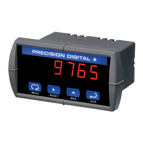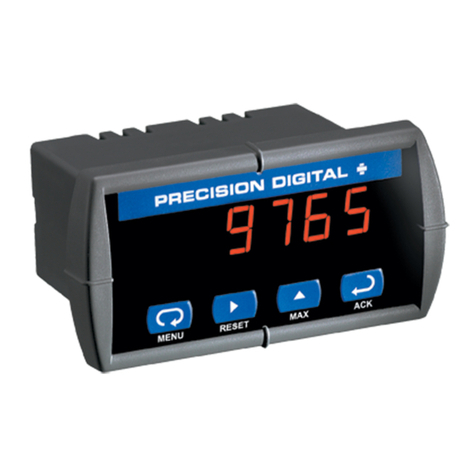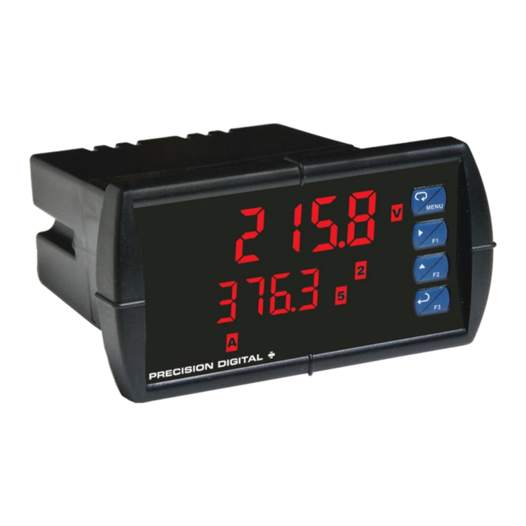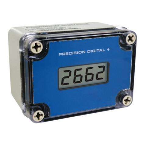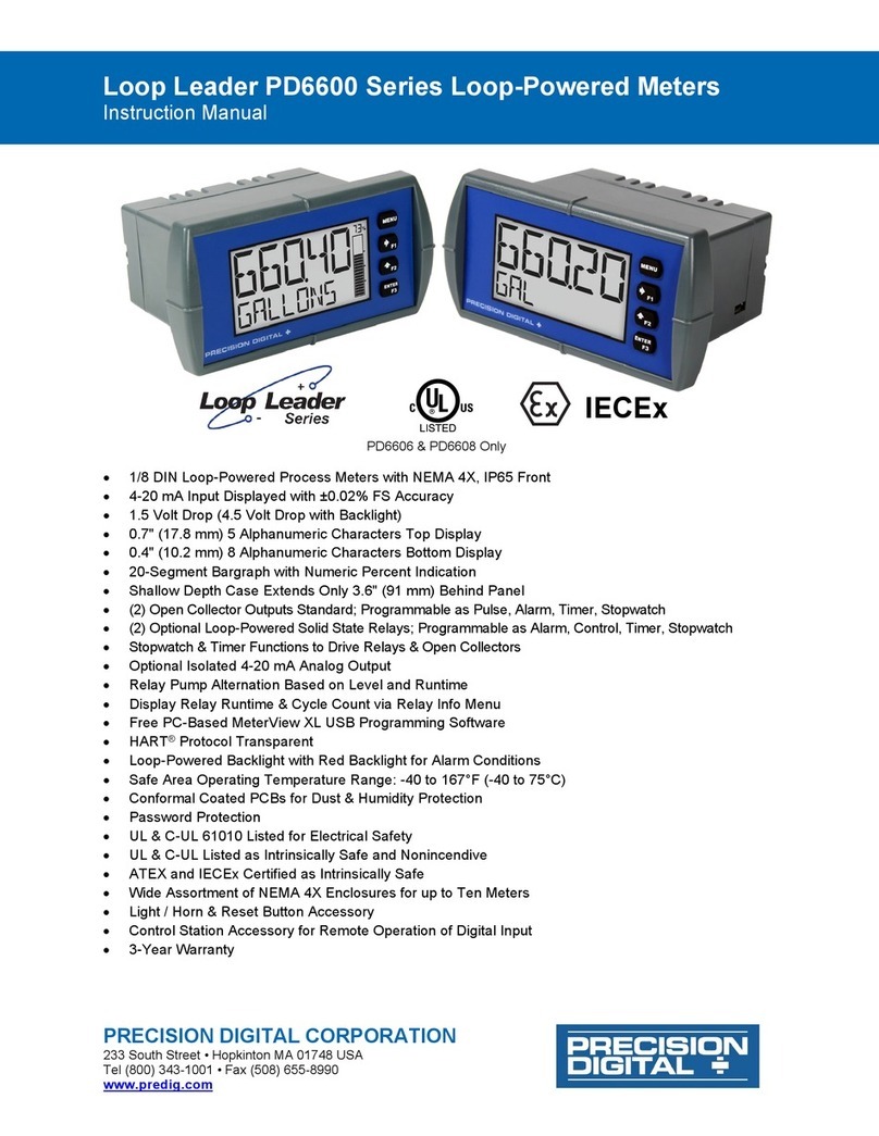
PD743 Sabre T Temperature Meter
Instruction Manual
Disclaimer
The information contained in this document is
subject to change without notice. Precision Digital
makes no representations or warranties with
respect to the contents hereof, and specifically
disclaims any implied warranties of merchantability
or fitness for a particular purpose.
Safety Information
• Read complete instructions prior to installation
and operation of the meter.
• Risk of electric shock or personal injury.
Hazardous voltages exist within enclosure.
• Installation and service should be performed
only by trained service personnel.
• This product is not recommended for life
support applications or applications where
malfunctioning could result in personal injury
or property loss. Anyone using this product
for such applications does so at their own
risk. Precision Digital Corporation shall not be
held liable for damages resulting from such
improper use.
• J, K, T, E Thermocouple & 100 Ω Pt RTD
• Pre-Calibrated for All Input Types
• Type 4X, NEMA 4X, IP65 Front
• Shallow Depth Case 3.2" Behind Panel
• 4 Digit Display, 0.56" (14 mm) High, Red LEDs
• Easy Front Panel Programming
• Maximum/Minimum Display
• Universal Power Supply 85-265 VAC
• 12-36 VDC/12-24 VAC Power Option
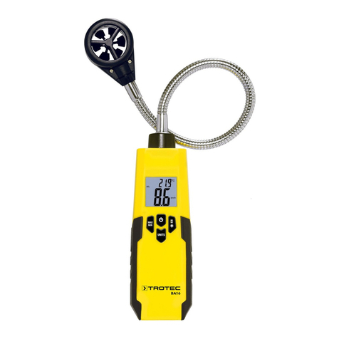
The Sabre T model PD743 is an easy-to-use
temperature meter. It accepts type J, K, T, E
thermocouple and 100 Ω platinum RTD sensors.
The four front panel buttons make the setup and
programming an easy task.
© 2023 Precision Digital Corporation.
All rights reserved.
WARNING
Cancer and Reproductive Harm
www.P65Warnings.ca.gov
Specications
Except where noted all specifications apply to operation at +25°C.
General
DISPLAY 0.56" (14 mm) high, red LED, four digits, automatic lead zero blanking.
DISPLAY UPDATE RATE RTD: 5/second
Thermocouple: 2.5/second
OVERRANGE Display flashes 9999
UNDERRANGE Display flashes -1999
PROGRAMMING METHODS Four front panel buttons
RECALIBRATION All ranges are calibrated at the factory. Recalibration is recommended at least
every 12 months.
MAX/MIN DISPLAY Max/min readings reached by the process are stored until reset by the user or
until power to the meter is turned off.
PASSWORD Programmable password restricts modification of programmed settings.
NON-VOLATILE MEMORY All programmed settings are stored in non-volatile memory for a minimum of
ten years if power is lost.
POWER OPTIONS 85-265 VAC, 50/60 Hz; 90-265 VDC, 8 W max or 12-36 VDC, 12-24 VAC,
6 W max
FUSE Required fuse: UL Recognized, 5 A max, slow blow
Up to 6 meters may share one 5 A fuse
NORMAL MODE REJECTION 64 dB at 50/60 Hz
ISOLATION 4 kV input-to-power line
OVERVOLTAGE CATEGORY Installation Overvoltage Category II:
Local level with smaller transient overvoltages than Installation Overvoltage
Category III.
ENVIRONMENTAL Operating temperature range: 0 to 65°C
Storage temperature range: -40 to 85°C
Relative humidity: 0 to 90% non-condensing
CONNECTIONS Removable screw terminal blocks accept 12 to 22 AWG wire, RJ11 for factory
use only.
ENCLOSURE 1/8 DIN, high impact plastic, UL 94V-0, color: gray
MOUNTING 1/8 DIN panel cutout required. Two panel mounting bracket assemblies
provided
TIGHTENING TORQUE Screw terminal connectors: 5 lb-in (0.56 Nm)
OVERALL DIMENSIONS 2.45" x 4.68" x 3.79" (62 mm x 119 mm x 96 mm) (H x W x D)
WEIGHT 8.5 oz (241 g)
WARRANTY 1 year parts & labor
EXTENDED WARRANTY 1 or 2 years, refer to the Price List for details.
Temperature Inputs
INPUTS Field selectable: Type J, K, T, or E thermocouples;
100 Ωplatinum RTD (0.00385 or 0.00392 curve)
RESOLUTION 1Ωfor all thermocouples and RTD inputs
1Ωor 0.1Ωfor Type T thermocouple
ACCURACY Input Type Range Accuracy
Type J -58° to 1382° F
-50° to 750°C
±2°F
±1°C
Type K -58° to 2300° F
-50° to 1260°C
±2°F
±1°C
Type T -292° to 700° F
-180° to 371°C
±2°F
±1°C
Type T
0.1° Res
-199.9° to 700.0° F
-180.0° to 371.0°C
±1.8°F
±1.0°C
Type E -58° to 1700°F
-50° to 927°C
±2°F
±1°C
100 ΩRTD -328° to 1382°F
-200° to 750°C
±1°F
±1°C
COLD JUNCTION REFERENCE Automatic, fixed, no user calibration needed
TEMPERATURE DRIFT ±2°C maximum; 0 to 65°C ambient temperature
INPUT IMPEDANCE Greater than 100 kΩ
Safety
UL LISTED USA and Canada
UL 508 Industrial Control Equipment
UL FILE NUMBER E160849
FRONT PANEL UL Type 4X, NEMA 4X, IP65; panel gasket provided
LOW VOLTAGE DIRECTIVE EN 61010-1
Safety requirements for measurement, control, and laboratory use
Electromagnetic Capability
EMISSIONS EN 55011
Group 1 Class A ISM emissions requirements
Radiated Emissions Class A
AC Mains Conducted Emissions Class A
IMMUNITY EN 61326-1
Measurement, control, and laboratory equipment
EN 61000-6-2
EMC heavy industrial generic immunity standard
RFI - Amplitude Modulated 80 -1000 MHz 10 V/m 80% AM (1 kHz)
1.4 - 2.0 GHz 3 V/m 80% AM (1 kHz)
2.0 - 2.7 GHz 1 V/m 80% AM (1 kHz)
Electrical Fast Transients ±2kV AC mains, ±1kV other
Electrostatic Discharge ±4kV contact, ±8kV air
RFI - Conducted 10V, 0.15-80 MHz, 1kHz 80% AM
AC Surge ±2kV Common, ±1kV Differential
Surge 1KV (CM)
Power-Frequency Magnetic Field 30 A/m 70%V for 0.5 period
Voltage Dips 40%V for 5 & 50 periods
70%V for 25 periods
Voltage Interruptions <5%V for 250 periods
Note: Testing was conducted on PD743 meters installed through the covers of grounded metal enclosures
with cable shields grounded at the point of entry representing installations designed to optimize EMC
performance.
Ordering Information
85-265 VAC*
Model
12-36 VDC*
Model
Description
PD743-6R0-0 PD743-7R0-0 Temperature
Meter
*All models may be powered from AC or DC, see
Specifications for details.
NEMA 4 & NEMA 4X Enclosures
Model # of
Meters
Description Mounting
PDA2300 1 - 6 Plastic NEMA
4X Enclosure
Through Door
PDA2600 1 - 6 Stainless
Steel NEMA
4X Enclosure
Through Door
PDA2700 1 - 6 Steel NEMA
4X Enclosure
Through Door
PDA2801 1 Plastic NEMA
4X Enclosure
Through
Cover
PDA2812 2 Plastic NEMA
4X Enclosure
Through
Cover
PDA3407 1 Plastic NEMA
4X Enclosure
Behind Clear
Window
PDA3411 2 Plastic NEMA
4X Enclosure
Behind Clear
Window
PDA3412 3 Plastic NEMA
4X Enclosure
Behind Clear
Window
Overview
There are no jumpers involved in the setup process
of the meter. The RTD/TC selector switch, located
between the SIGNAL and RJ11 connectors, must
be set accordingly for the meter to accept RTD or
thermocouple inputs. Setup and programming is
done through the front panel buttons. After power
and signal connections have been completed and
verified, apply power to the meter.
Front Panel
1743
Buttons Operation
Button
Symbol
Description
Menu: Press the Menu button
to enter or exit the Programming
Mode at any time.
Right Arrow: Press the Right
arrow button to move to the next
digit during digit or decimal point
programming.
Up Arrow: Press or hold the Up
arrow button to scroll through
the menus, decimal point, or to
increment the value of a digit.
Enter: Press the Enter button
to access a menu or to accept
a setting.
EU Declaration of
Conformity
For shipments to the EU and UK, a Declaration
of Conformity was printed and included with the
product.
For reference, a Declaration of Conformity is also
available on our website www.predig.com/docs.


