PRECISION DIGITAL PD755 User manual

PRECISION DIGITAL CORPORATION
19 Strathmore Road • Natick MA 01760 USA
Tel (800) 343-1001 • Fax (508) 655-8990
www.predig.com
DIGITAL METERS
Large Display Temperature Meters
Instruction Manual
• Handles Thermocouple and RTD Inputs with Simplicity
• J, K, T, E, R and S Thermocouples
• 100 ΩPlatinum RTDs (0.00385 or 0.00392 curve)
• Large Display Readouts: 2.3", 1.0" and 0.8" High
• Display Resolution
Thermocouples: 1°, Type T T/C Displayed to 1°or 0.1°
RTDs Resolution: 1°or 0.1°, Field Selectable
• Displays °F or °C, Field Selectable
• No Calibration Necessary – Factory Calibrated
• Maximum/Minimum Temperature Display
• Input Offset Adjustment
• NEMA 4X and Explosion-Proof Enclosures
• 115 or 230 VAC Power, Field Selectable
• 24 VDC Powered Models, Optional
• 24 VDC Isolated Power Supply Standard on AC Models
• 4 Visual Alarm Points with Front Panel LED Status Indication
• 2 or 4 Relays and/or 4-20 mA Output Options

Large Display Temperature Meters Instruction Manual
2
Visit our website
http://www.predig.com

Large Display Temperature Meters Instruction Manual
3
Table of Contents
INTRODUCTION ----------------------------------------------------------------------- 7
Ordering Information ------------------------------------------------------------------------7
Model PD755 --------------------------------------------------------------------------------7
Model PD756 --------------------------------------------------------------------------------7
Model PD757 --------------------------------------------------------------------------------8
Accessories ----------------------------------------------------------------------------------8
Safety Notice -----------------------------------------------------------------------------------9
Specifications-------------------------------------------------------------------------------- 10
Basic Temperature Meter -------------------------------------------------------------- 10
Options -------------------------------------------------------------------------------------- 12
Display Functions and Messages----------------------------------------------------- 14
SETUP AND PROGRAMMING -------------------------------------------------- 15
Overview--------------------------------------------------------------------------------------- 15
Disassembling the Meter----------------------------------------------------------------- 16
Disassembling the PD755 -------------------------------------------------------------- 16
Disassembling the PD756 -------------------------------------------------------------- 16
Disassembling the PD757 -------------------------------------------------------------- 17
Reassembling the Meter ----------------------------------------------------------------- 18
Reassembling the PD755 -------------------------------------------------------------- 18
Reassembling the PD756 -------------------------------------------------------------- 18
Reassembling the PD757 -------------------------------------------------------------- 18
Jumper Configuration--------------------------------------------------------------------- 19
Input Selection and Lockout Jumpers (Main PCB)------------------------------- 19
Relay Acknowledge Enable (Display PCB) ---------------------------------------- 19
Fail-Safe Operation of Relays (Options PCB)------------------------------------- 19
Power Selection----------------------------------------------------------------------------- 20
Overview------------------------------------------------------------------------------------ 20
Changing from 115 to 230 VAC Power --------------------------------------------- 20
Labeling Meter for 115 VAC, 230 VAC or 24 VDC------------------------------- 21
Connections---------------------------------------------------------------------------------- 21
Overview------------------------------------------------------------------------------------ 21
Wiring Instructions------------------------------------------------------------------------ 22
Power Connections ---------------------------------------------------------------------- 23
Signal Connections----------------------------------------------------------------------- 24
Enter, Acknowledgement, and Hold Connections -------------------------------- 26
Optional Relays & 4-20 mA Output Terminals ------------------------------------ 27
Isolated 4-20 mA Output Transmitter Connections ------------------------------ 28

Large Display Temperature Meters Instruction Manual
4
Programming -------------------------------------------------------------------------------- 29
Overview------------------------------------------------------------------------------------ 29
Select Type of Input Signal T/C or RTD----------------------------------------- 29
ENTER Button Functionality ------------------------------------------------------- 30
ACK Button Functionality ----------------------------------------------------------- 30
Magnetic Reed Switch Functionality --------------------------------------------- 30
General Programming Description --------------------------------------------------- 31
Five Basic Digit/Display-Setting Instructions ----------------------------------- 31
Programming the Basic Meter--------------------------------------------------------- 32
Selecting Type of T/C or RTD (TYPE) -------------------------------------------- 33
Select °F or °C (f or C) ------------------------------------------------------------ 33
Alarm Setup and Set Points Programming----------------------------------------- 34
Overview -------------------------------------------------------------------------------- 34
Set Relays for Manual or Automatic Reset ------------------------------------- 34
Set Relays for Fail-Safe Operation ----------------------------------------------- 34
Setup for Latching or Non-Latching Relays (SetuP) ------------------------- 35
Alarm Set and Reset Points Programming ------------------------------------- 36
Programming Alarm Points Using Set Points (setpts) Menu ------------- 37
Alarm Set and Reset Programming Confirmation ---------------------------- 37
Isolated 4-20 mA Output Transmitter Option -------------------------------------- 38
4-20 mA Output Programming (output) ---------------------------------------- 38
4-20 mA Output Programming Confirmation ----------------------------------- 38
Input Offset Adjustment (OFFSEt) ---------------------------------------------------- 39
Lockout Jumper --------------------------------------------------------------------------- 39
OPERATION -------------------------------------------------------------------------- 40
Overview--------------------------------------------------------------------------------------- 40
Basic Meter Operation -------------------------------------------------------------------- 41
Overview------------------------------------------------------------------------------------ 41
Maximum/Minimum Temperature Display------------------------------------------ 41
Relays Operation --------------------------------------------------------------------------- 42
Overview------------------------------------------------------------------------------------ 42
Relays Auto Initialization---------------------------------------------------------------- 42
Fail-Safe Operation ---------------------------------------------------------------------- 42
Front Panel LEDs------------------------------------------------------------------------- 43
Acknowledging Relays ------------------------------------------------------------------ 45
Switching Inductive Loads-------------------------------------------------------------- 46
4-20 mA Output Operation ------------------------------------------------------------- 46
RECALIBRATION (CALIB) -------------------------------------------------------- 47
Calibration Error (error) --------------------------------------------------------------- 47
Recommended Calibration Points ---------------------------------------------------- 48
Minimum Input Span--------------------------------------------------------------------- 48
Calibration Verification ------------------------------------------------------------------- 48

Large Display Temperature Meters Instruction Manual
5
INSTALLATION ---------------------------------------------------------------------- 49
Wall Mounting Instructions ------------------------------------------------------------- 49
PD755 Mounting -------------------------------------------------------------------------- 49
PD756 Mounting -------------------------------------------------------------------------- 49
PD757 Mounting -------------------------------------------------------------------------- 49
Panel Mounting Instructions------------------------------------------------------------ 50
PD755 Panel Mounting Instructions ------------------------------------------------- 50
PD757 Panel Mounting Instructions ------------------------------------------------- 51
Pipe Mounting Instructions for PD755 and PD756 ------------------------------ 53
Explosion-Proof Control Stations----------------------------------------------------- 55
OPTION CARD REMOVAL & INSTALLATION ----------------------------- 56
Option Card Installation in PD755 ---------------------------------------------------- 56
Option Card Installation in PD756 ---------------------------------------------------- 58
Option Card Installation in PD757 ---------------------------------------------------- 59
MODEL SENSITIVE ILLUSTRATIONS ---------------------------------------- 60
Removing the Display PCB ------------------------------------------------------------- 60
Locations of Connections and Jumpers-------------------------------------------- 61
Jumper Arrays and Status LEDs ------------------------------------------------------ 63
Front Panel Displays ---------------------------------------------------------------------- 65
Overall Dimensions ------------------------------------------------------------------------ 66
Wall Mounting Dimensions-------------------------------------------------------------- 67
PROGRAMMED PARAMETER SETTINGS ---------------------------------- 69
OTHER PRECISION DIGITAL PRODUCTS---------------------------------- 70

Large Display Temperature Meters Instruction Manual
6
List of Figures
Figure 1. Input Power Label ................................................................. 21
Figure 2. Input Power Connections for 756 and 757 .......................... 23
Figure 3. Four-Wire RTD Connections ................................................ 24
Figure 4. Three-Wire RTD Connections............................................... 24
Figure 5. Two-Wire RTD Connections ................................................. 25
Figure 6. Thermocouple Connections................................................. 25
Figure 7. External Control Connections.............................................. 26
Figure 8. Relay and 4-20 mA Output Terminals .................................. 27
Figure 9. Output Loop Powered by Meter ........................................... 28
Figure 10. Output Loop Powered from External Power Supply........... 28
Figure 11. JP1 Input Signal Selection Array. ......................................... 29
Figure 12. Reed Switch Operation.......................................................... 30
Figure 13. AC and DC Loads Protection ................................................ 46
Figure 14. Low Voltage DC Loads Protection ....................................... 46
Figure 15. PD755 Panel Mounting .......................................................... 50
Figure 16. PD757 Panel Mounting .......................................................... 51
Figure 17. PD757 Panel Mounting Cutout Dimensions......................... 51
Figure 18. 755 Pipe Mounting Assembly................................................ 53
Figure 19. 756 Pipe Mounting Assembly................................................ 53
Figure 20. Pipe Mounting Plate............................................................... 54
Figure 21. Explosion-proof Control Station........................................... 55
Figure 22. Removing the PD755 Display PCB ....................................... 56
Figure 23. PD755 Options PCB Standoffs Location.............................. 56
Figure 24. PD755 Options PCB Installation ........................................... 57
Figure 25. PD756 Option PCB Installation ............................................. 58
Figure 26. PD756 Option PCB Installed ................................................. 58
Figure 27. PD757 Option PCB Installation ............................................. 59
Figure 28. Removing the Display PCB on PD755 .................................. 60
Figure 29. Removing the Display PCB on PD756 .................................. 60
Figure 30. Removing the Display PCB on PD757 .................................. 61
Figure 31. PD755 Connectors and Jumper Location ............................ 61
Figure 32. PD756 Connectors and Jumper Location ............................ 62
Figure 33. PD757 Connectors and Jumper Location ............................ 62
Figure 34. PD755 Jumper Arrays and Status LED Identification ......... 63
Figure 35. PD756 Jumper Arrays and Status LED Identification ......... 63
Figure 36. PD757 Jumper Arrays and Status LED Identification ......... 64
Figure 37. PD755 Front Panel Display.................................................... 65
Figure 38. PD756 Front Panel Display.................................................... 65
Figure 39. PD757 Front Panel Display.................................................... 65
Figure 40. PD755 Overall Dimensions.................................................... 66
Figure 41. PD756 Overall Dimensions.................................................... 66
Figure 42. PD757 Overall Dimensions.................................................... 67
Figure 43. PD755 Wall Mounting Dimensions ....................................... 67
Figure 44. PD755 Wall Mounting Screw Installation ............................. 67
Figure 45. PD756 Wall Mounting Dimensions ....................................... 68
Figure 46. PD757 Wall Mounting Dimensions ....................................... 68

Large Display Temperature Meters Instruction Manual
7
INTRODUCTION
The Large Display Temperature Meters are housed in rugged, NEMA 4X
or explosion-proof enclosures. These meters handle temperature display
and alarm applications with simplicity, accuracy, and reliability. They
accept the common thermocouples J, K, T, E, R, and S or 100 Ω
platinum RTDs. Options include up to 4 relays for alarms as well as an
isolated 4-20 mA transmitter output. An isolated 24 VDC power supply is
available as standard feature on AC powered models to power the
transmitter output.
Ordering Information
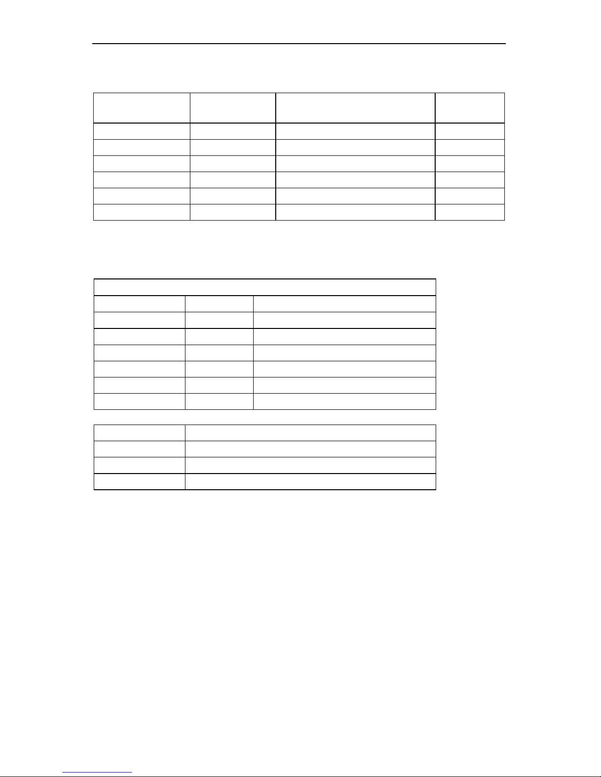
Model PD755
115/230 VAC
MODEL
24 VDC
MODEL
DESCRIPTION Option
Card*
PD755-N PD755-2-N No Options
PD755-44 PD755-2-44 2 Relays PD474
PD755-45 PD755-2-45 4-20 mA Output PD475
PD755-46 PD755-2-46 2 Relays + 4-20 mA Output PD476
PD755-47 PD755-2-47 4 Relays PD477
PD755-48 PD755-2-48 4 Relays + 4-20 mA Output PD478
Model PD756
115/230 VAC
MODEL
24 VDC
MODEL
DESCRIPTION Option
Card*
PD756-N PD756-2-N No Options
PD756-44 PD756-2-44 2 Relays PD474
PD756-45 PD756-2-45 4-20 mA Output PD475
PD756-46 PD756-2-46 2 Relays + 4-20 mA Output PD476
PD756-47 PD756-2-47 4 Relays PD477
PD756-48 PD756-2-48 4 Relays + 4-20 mA Output PD478
*Option Cards (When Ordered Separately)
Large Display Temperature Meters Instruction Manual
8
Model PD757
115/230 VAC
MODEL
24 VDC
MODEL
DESCRIPTION Option
Card*
PD757-N PD757-2-N No Options
PD757-34 PD757-2-34 2 Relays PD374
PD757-35 PD757-2-35 4-20 mA Output PD375
PD757-36 PD757-2-36 2 Relays + 4-20 mA Output PD376
PD757-37 PD757-2-37 4 Relays PD377
PD757-38 PD757-2-38 4 Relays + 4-20 mA Output PD378
*Option Cards (When Ordered Separately)
Accessories
Control Stations
Model Switches Labels
PDA2451-E 1 ENTER
PDA2451-A 1 ACK
PDA2451-R 1 RESET
PDA2452-EA 2 ENTER and ACK
PDA2452-ER 2 ENTER and RESET
PDA2453-EAR 3 ENTER, ACK, and RESET
PDA-MAG Magnet Assembly for PD656 & PD756
PDA6504 Panel Mounting Kit for PD757**
PDA6554 Panel Mounting Kit for PD755**
PDA6545 2" Pipe Mounting Kit for PD755 and PD756
** These panel mounting kits are not intended to provide waterproof protection to
the panel.

Large Display Temperature Meters Instruction Manual
9
Safety Notice
!
CAUTION: Read complete
instructions prior to installation and
operation of the meter.
WARNING: Risk of electric shock.
!
Observe all safety regulations. Electrical wiring should be performed in
accordance with all applicable national, state, and local codes to
prevent damage to the meter and ensure personnel safety.
!
It is recommended to use this meter in a fail-safe system that
accommodates the possibility of meter failure or power failure.
WARNING
Hazardous voltages exist within enclosure. Installation and service should
be performed only by trained service personnel.
AVERTISSEMENT
Les pièces à l'intérieur du boîtier portent des tensions dangereuses. Seules
des personnes qualifiées et bien entrainées devraient entreprondre
l'ótalonnage et la maintenance.
Disclaimer
The information contained in this document is subject to change without notice.
Precision Digital makes no representations or warranties with respect to the
contents hereof, and specifically disclaims any implied warranties of
merchantability or fitness for a particular purpose.

Large Display Temperature Meters Instruction Manual
10
Specifications
Except where noted all specifications apply to operation at +25°C.
Basic Temperature Meter
INPUTS Field selectable: type J, K, T, E, R, or S thermocouples with 1°
resolution; type T to 0.1°; 100 Ωplatinum RTD (0.00385 or
0.00392 curve) to 1°or 0.1°resolution.
DISPLAY 4½ digit, high efficiency red LED, automatic lead zero blanking,
F or C displayed to indicate Fahrenheit or Celsius.
Digit Size:
PD755– 1.0" (25.4 mm) high
PD756– 0.8" (20.3 mm) high
PD757– 2.3" (58.0 mm) high
COLD JUNCTION
REFERENCE
Automatic, fixed, no user calibration needed.
INPUT
IMPEDANCE
Greater than 100 kΩ
LOCKOUT Jumper JP2, located on Main PCB, restricts modification of set
values.
ACCURACY Input
Type Range Accuracy
Type J T/C –328°to 1382°F
–200°to 750°C
±2°F
±1°C
Type K T/C –328°to 2498°F
–200°to 1330°C
±2°F
±1°C
Type T T/C –330.0°to 760.0°F
–200.0°to 404.0°C
±2°F
±1°C
Type E T/C –328°to 1832°F
–200°to 1000°C
±2°F
±1°C
Type R T/C 32°to 3213°F
0°to 1767°C
±5°F
±3°C
Type S T/C 40°to 3214°F
4°to 1768°C
±6°F
±3°C
100 ΩRTD –328.0°to 1382.0°F
–200.0°to 750.0°C
±0.7°F
±0.4°C
RECALIBRATION All ranges are calibrated at the factory. Recalibration is
recommended at least every 12 months.
INPUT OFFSET Programmable to ±100% FS display. This parameter allows the
user to apply an offset value to the input temperature being
displayed.
SENSOR BREAK
DETECTION
Open sensor circuit indicated by display flashing OPEn. All relays
and alarm status LEDs go to alarm state.
MAX/MIN
TEMPERATURE
DISPLAY
The maximum and minimum temperature reached by the process
is stored in memory until cleared (reset) by the user or until power
to the meter is turned off. Max/min values are displayed via the
ENTER button and HI t, LO t menu functions, respectively.

Large Display Temperature Meters Instruction Manual
11
ALARM POINTS Four, any combination of high or low alarms. Latching or non-
latching.
ALARM POINT
DEADBAND
0-100% of full scale, user selectable
ALARM STATUS
INDICATION
Front panel LED
NON-VOLATILE
MEMORY
All programming values are stored in non-volatile memory for a
minimum of ten years if power is lost.
NORMAL MODE
REJECTION
64 dB at 50/60 Hz
POWER AC Power:115 VAC or 230 VAC ±10%, 50/60 Hz, 12 VA
DC Power: 22-28 VDC, 12 watts maximum
ENVIRONMENTAL Operating temperature range: 0 to +65°C
Storage temperature range: -40 to +85°C
Relative humidity: 0 to 90% non-condensing
CONNECTIONS Removable screw terminal blocks accept 22 to 12 AWG wire.
ENCLOSURE
PD755 Impact-resistant glass filled polycarbonate, NEMA 4X, modified
specifically for PDC; two holes for ½" conduit provided at base.
PD756 Explosion-proof sand-cast aluminum – 0.3% max. copper content,
NEMA 3, 4, 7, 9. For use in hazardous locations Class I Groups C
& D, Class II Groups E, F & G (suitable for Division 1 and
Division 2). Two ¾" NPT holes provided at opposite sides. Up to
four holes can be provided for an additional charge.
PD757 Die cast aluminum, NEMA 4X, modified specifically for PDC; four
holes for ½" conduit provided at base, 3 plugs provided.
MOUNTING
PD755 Enclosure contains four holes for wall mounting. Panel mounting
and pipe mounting kits available.
PD756 Enclosure contains four 7/16" holes for wall-mounting, pipe
mounting kit available.
PD757 Enclosure contains four ¼" holes for wall-mounting. Panel
mounting kit available.
OVERALL DIMENSIONS
PD755 6.7" x 5.5" x 3.7" (170 mm x 140 mm x 95 mm)
PD756 8.0" x 8.0" x 5.7" (203 mm x 203 mm x 145 mm)
PD757 4.9" x 14.3" x 3.2" ( 125 mm x 362 mm x 81 mm)
WEIGHT
PD755 3.8 lbs (1.73 kg)
PD756 14.6 lbs (6.6 kg)
PD757 7.0 lbs (3.2 kg)
WARRANTY 1 year parts and labor
EXTENDED
WARRANTY
Warranty may be extended an additional 12 months by returning the
Product Registration Form within 2 months from date of purchase. Go to
www.predig.com for online registration.

Large Display Temperature Meters Instruction Manual
12
Options
Relays
RATING 2 or 4 SPDT (form C); rated 2 Amp @ 30 VDC or 2 Amp @ 250
VAC resistive load; 1/14 HP @ 125 / 250 VAC for inductive loads.
RESET User select via JP5 jumper array and SetuP menu.
Automatic reset only.
Manual reset only, at any time.
Automatic plus manual reset at any time.
Manual reset only after alarm condition has been corrected.
Automatic reset: Relays will automatically reset when the input
passes the reset point.
Manual reset: It can be performed via user supplied external
contact closure at terminals AK and CM or front panel ACK
button. Manual reset resets all manually resetable relays.
BUILT-IN
SUPPRESSION
A built-in suppressor (snubber) to prolong the life of the relays
protects each relay contact. The suppressor provides a degree
of protection against electrical noise caused by inductive loads.
Suppressor value, .01 µF/470 Ω, 250 VAC.
DEADBAND 0-100% of full scale, user selectable.
FAIL-SAFE
OPERATION
Relay coils are energized in non-alarm condition. In case of
power failure, relays will go to alarm state. Fail-safe operation
may be disabled, by removing jumper J5 located on the Options
PCB.
SENSOR BREAK
DETECTION
Open sensor circuit indicated by display flashing OPEn. All relays
and alarm status LEDs go to alarm state.
AUTO
INITIALIZATION
When power is applied to the meter, the relays always reflect the
state of the input to the meter.

Large Display Temperature Meters Instruction Manual
13
Isolated 4-20 mA Transmitter Output
CALIBRATION
RANGE
The transmitter output can be calibrated so that a 4 mA output is
produced for any number displayed on the meter. The 20 mA
output may correspond to any number displayed on the meter
(larger or smaller). However, best results are obtained with a
500-count difference between 4 and 20 mA displays.
The output will be linear (example: 4 mA = 0°, 20 mA = 1000°,
output is 6 mA at 125°.)
ACCURACY ±0.1% F.S., ±.004 mA @ 25°C
NO EQUIPMENT
NEEDED
The 4-20 mA output from the Temperature Meter is calibrated
via the ENTER button without the use of a calibrator.
OUTPUT LOOP-
POWER
24 VDC ± 5% @ 20 mA, regulated. Maximum loop resistance is
1200 Ω. Isolated from input signal.
ISOLATION 500 VDC or peak AC, input-to-output or input/output-to-power
line.
EXTERNAL
LOOP-POWER
SUPPLY
35 VDC maximum
OUTPUT LOOP
RESISTANCE
Power supply Minimum loop
resistance
Maximum loop
resistance
24 VDC
10 Ω600 Ω
35 VDC (external) 600 Ω1000 Ω

Large Display Temperature Meters Instruction Manual
14
Display Functions and Messages
The meter displays various functions and messages during operation and
programming. The following table shows the various displayed functions and
messages with their description.
Display Parameter Description/Comments
9999F Out of range Indicates the input signal exceeds the full-scale
range of the meter.
CALIb Calibration Calibrates meter using a calibrated signal source.
CLEAr Clear Clears (resets) maximum or minimum temperatures
reached by the process.
DIA9 Diagnostic Displays parameter settings one at a time for
diagnostic purposes. Setting can not be changed
under this function.
Error Error Indicates calibration was not successful.
F or C °F or °C Type of scale to be used Fahrenheit or Celsius.
HI t High temperature Displays maximum temperature reached by the
process since last cleared (reset).
InPt 1 Input 1 Sets low input calibration (low input signal must be
applied to the meter).
InPt 2 Input 2 Sets high input calibration (high input signal must
be applied to the meter).
LO t Low temperature Displays minimum temperature reached by the
process since last cleared (reset).
LatCk Latch Sets alarm set points for latching or non-latching
relay operation.
OFFSET Input offset Adds or subtracts a programmed offset value to the
input.
Open Open Indicates open sensor circuit.
outPut Output Sets the optional 4-20 mA output values.
Set 1 Set point 1 Sets operation for Set point 1.
Set 2 Set point 2 Sets operation for Set point 2.
Set 3 Set point 3 Sets operation for Set point 3.
Set 4 Set point 4 Sets operation for Set point 4.
SetPtS Set points Sets alarm set and reset point values.
Setup Setup Sets operation of set points for latching or non-
latching mode.
Type Type Sets type of thermocouple or RTD to be used as
the input. Jumper JP1 must be configured
accordingly.

Large Display Temperature Meters Instruction Manual
15
SETUP AND PROGRAMMING
Overview
To setup and program the Digital Temperature Meter, it is necessary to
disassemble the Display PCB. See disassembling instructions in the next pages.
Setting up and programming the Digital Temperature Meter involves four basic
steps:
1. Jumper Configuration (Page 19)
a. Input selection and lockout jumpers
b. Relay acknowledge enable
c. Fail-safe operation of relays
2. Power Selection (Page 20)
a. Changing to 230 VAC power if needed. 115 VAC is factory default on
AC powered models.
b. Labeling meter for power input: 115 VAC or 230 VAC (24 VDC powered
models are labeled as such at the factory).
3. Connections (Page 21)
a. Power connections
b. Signal connections
c. Enter, acknowledgement, and hold reading
d. Relays connections
e. 4-20 mA output connections
4. Programming (Page 29)
a. Basic meter
b. Alarm setup and set points
c. 4-20 mA output
d. Lockout jumper
Programmed Parameter Settings
To simplify programming, write down the desired programming values prior to
attempting to program the meter. The Programmed Parameter Settings form,
located on page 69, provides a convenient method to record the user settings; it
also provides the factory setting for most of the programmable parameters.

Large Display Temperature Meters Instruction Manual
16
Disassembling the Meter
To perform the steps described above, it is necessary to partially disassemble the
meter. Main PCB may remain attached to enclosure’s base even during conduit
hub installation if proper precautions are taken.
Disassembling the PD755
1. Loosen the four screws that hold enclosure’s cover and remove the cover.
2. Remove the four mounting screws holding the Display PCB (see Figure 28,
page 60).
3. Move Display PCB out of the way. Ribbon cable to Display PCB may be
removed during meter installation. Do not remove standoffs from Main
PCB. Main PCB is secured to enclosure’s base with four mounting screws.
4. Change voltage selection as required; this is described on page 20. Set
configuration jumpers; connect power and signal wires.
5. Reassemble Display PCB prior to applying power.
6. Program meter prior to installing enclosure’s cover.
7. Install lockout jumper to prevent accidental changes to programmed settings.
Disassembling the PD756
!
When servicing the PD756 in a hazardous area, all appropriate
hazardous area procedures must be followed.
1. Remove enclosure’s cover.
2. Loosen the two mounting screws on the right side of the Display PCB (see
Figure 29 on page 60). It is not necessary to remove the faceplate.
3. Remove the two mounting screws on the left side of the Display PCB.
4. Slide the Display PCB out from under the screws. Ribbon cable to Display
PCB may be removed during meter installation. Do not remove standoffs
from Main PCB. Main PCB is secured to enclosure’s base with four
mounting screws.
5. Change voltage selection as required, described on page 20. Set
configuration jumpers; connect power and signal wires.
6. Reassemble the Display PCB prior to applying power.
7. To program meter using front panel buttons leave cover off until meter
programming is complete.
8. Install lockout jumper to prevent accidental changes to programmed settings.

Large Display Temperature Meters Instruction Manual
17
Disassembling the PD757
1. Loosen the four screws that hold the enclosure’s cover in place and remove
cover.
2. Loosen the top three mounting screws holding the Display PCB (see Figure
30, page 61).
3. Remove the bottom three mounting screws.
4. Slide Display PCB out from under the top three screws. Ribbon cable to
Display PCB may be removed during meter installation. Do not remove
standoffs from Main PCB. Main PCB is secured to enclosure’s base with
four mounting screws.
5. Change voltage selection as required, described on page 20. Set
configuration jumpers; connect power and signal wires.
6. Reassemble Display PCB prior to applying power.
7. To program meter using front panel buttons leave top cover off until meter
programming is complete.
8. Install lockout jumper to prevent accidental changes to programmed settings.

Large Display Temperature Meters Instruction Manual
18
Reassembling the Meter
After the wiring and jumper selections have been made, reassemble the Display
PCB.
Reassembling the PD755
1. Place the Display PCB on top of the four standoffs. Make sure the ribbon
cable is connected to the connector on the Display PCB.
2. Replace the four mounting screws (see Figure 28 on page 60).
3. Install enclosure’s cover matching enclosure base and cover tabs.
4. Fasten the four screws that hold the enclosure cover in place.
Reassembling the PD756
1. Slide the Display PCB under the two screws on the right side of the Display.
PCB (see Figure 29 on page 60).
2. Replace the two mounting screws on the left side of the Display PCB.
3. Tighten the two mounting screws on the right side of the Display PCB
4. To program the meter using the front panel buttons leave cover off until
meter programming is complete.
5. Replace the enclosure cover.
Reassembling the PD757
1. Slide the Display PCB under the top three screws (see Figure 30, page 61).
2. Replace the bottom three mounting screws.
3. Tighten the top three mounting screws.
4. Align the enclosure cover so the alarm numbers on the cover are on the left
side of the meter and aligned with the alarm status LEDs.
5. To program the meter using the front panel buttons leave top cover off until
meter programming is complete.
6. Replace the enclosure cover and tighten the four screws that hold it in place.

Large Display Temperature Meters Instruction Manual
19
Jumper Configuration
Before programming the Digital Temperature Meter, it is necessary to configure
three jumper arrays. The jumper arrays are used for setting type of input signal
(thermocouple or RTD), lockout programmed settings, enable relay
acknowledgement (ACK), and setting relay fail-safe operation.
Input Selection and Lockout Jumpers (Main PCB)
Figure 31 on page 61 for PD755
Figure 32 on page 62 for PD756
Figure 33 on page 62 for PD757
Jumper JP1 Position Function
RTD RTD Input
TC Thermocouple Input
Jumper JP2 Position Function
LOCK Sets a lock on programming
functions
Relay Acknowledge Enable (Display PCB)
Figure 34 on page 63 for PD755
Figure 35 on page 63 for PD756
Figure 36 on page 64 for PD757
Jumper
JP5 Position
Function
1 Enable relay 1 manual reset
2 Enable relay 2 manual reset
3 Enable relay 3 manual reset
4 Enable relay 4 manual reset
Fail-Safe Operation of Relays (Options PCB)
Figure 24 on page 57 for PD755
Figure 25 on page 58 for PD756
Figure 27 on page 59 for PD757
Jumper
J5 Position
Function
On Apply fail-safe function to all relays
Off Disable fail-safe function to all relays

Large Display Temperature Meters Instruction Manual
20
Power Selection
Overview
Power Selection involves the following:
1. Changing to 230 VAC power if needed. 115 VAC is factory default on AC
powered models.
2. Labeling the meter as to how it will be powered: 115 VAC or 230 VAC.
Meters powered from 24 VDC are labeled as such at the factory.
Note: Meters ordered to operate from 24 VDC do not require any special
setup; this option is not field selectable.
Installation and configuration must be undertaken by qualified servicing
personnel.
!
When servicing the PD756 in a hazardous area, all appropriate
hazardous area procedures must be followed.
!
All AC powered meters are shipped from the factory set for 115 VAC
power. Do not apply 230 VAC without first setting up the Digital
Temperature Meter to accept this voltage. Otherwise it will cause
damage to the meter and endanger personnel.
!
Disconnect power prior to performing the following procedures.
All three meters are field selectable for either 115 VAC or 230 VAC
power. Changing the voltage selection involves the removal of the front
cover and the Display PCB, then selecting 115V or 230V on switch S1
located on the Main PCB.
!
Observe polarity for DC powered meters. Applying voltage with reverse
polarity may damage the meter.
Do not apply an AC voltage to DC powered meters. Applying an AC
voltage to DC powered meters will result in damage to the meter and
endanger personnel.
Changing from 115 to 230 VAC Power
To access the 115/230 VAC switch it is necessary to remove the housing cover
and the Display PCB, see Disassembling the Meter, page 16.
Once the Display PCB has been removed, switch S1 is visible. It is the large
black component with a red slide switch on the top, located next to the
transformer. For an illustration see:
Figure 31 on page 61 for PD755
Figure 32 on page 62 for PD756
Figure 33 on page 62 for PD757
For 115 VAC operation, the switch shows 115V; for 230 VAC it shows 230V.
Several setup steps are required and connections made while Display PCB is
removed, so it should not be reinstalled just yet. However, to avoid electric shock,
install Display PCB prior to applying power.
Other manuals for PD755
1
This manual suits for next models
2
Table of contents
Other PRECISION DIGITAL Test Equipment manuals


