BMS SR220 User manual


1
CONTENT
1OVERVIEW .......................................................................................................................................................................... 3
1.1 MEASUREMENT PRINCIPLE......................................................................................................................................................... 3
1.2 MEASUREMENT PRINCIPLE......................................................................................................................................................... 3
1.3 STANDARD PACKAGE ................................................................................................................................................................. 4
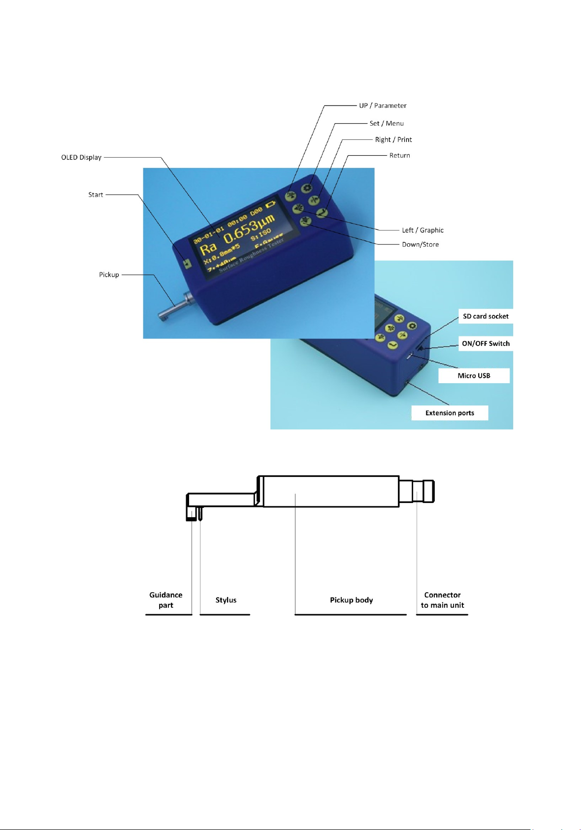
1.4 LAYOUT OF THE INSTRUMENT...................................................................................................................................................... 5
1.4.1 Main unit..................................................................................................................................................................... 5
1.4.2 Pickup .......................................................................................................................................................................... 5
1.4.3 Display......................................................................................................................................................................... 6
1.4.4 Function of key ............................................................................................................................................................ 6
1.5 BASIC CONNECTION METHOD...................................................................................................................................................... 7
1.5.1 Assembling and dis-assembling of the pickup............................................................................................................. 7
1.5.2 Charger and battery charging ..................................................................................................................................... 7
2SETTING FOR INITIAL USAGE ............................................................................................................................................... 7
2.1 CLOCK SETTING........................................................................................................................................................................ 8
2.2 UNITS OF MEASUREMENT .......................................................................................................................................................... 8
2.3 LANGUAGE SELECT ................................................................................................................................................................... 9
3MEASUREMENT OPERATION ............................................................................................................................................... 9
3.1 PREPARATION BEFORE MEASUREMENT.......................................................................................................................................... 9
3.2 SWITCH ON ............................................................................................................................................................................. 9
3.3 STYLUS POSITION.................................................................................................................................................................... 10
3.4 CALIBRATION......................................................................................................................................................................... 10
3.5GETTING STARTED .................................................................................................................................................................. 11
3.5.1 Start measuring......................................................................................................................................................... 11
3.6 RESULT DISPLAY ..................................................................................................................................................................... 11
3.6.1 Parameters ................................................................................................................................................................ 11
3.6.2 Profile Graphic........................................................................................................................................................... 11
3.6.3 Store/read measurements......................................................................................................................................... 12
3.6.4 Print measurements .................................................................................................................................................. 12
3.6.5 Connected with PC .................................................................................................................................................... 14
3.6.6 Remote measurement ............................................................................................................................................... 14
3.6.7 SD card ...................................................................................................................................................................... 14
4MAIN MENU ..................................................................................................................................................................... 14
4.1 MEASUREMENT CONDITION SETTING......................................................................................................................................... 15
4.2 SYSTEM SETTING.................................................................................................................................................................... 15
4.3 SOFTWARE INFORMATION ........................................................................................................................................................ 15
5ROUTINE MAINTENANCE AND CARE ................................................................................................................................. 16
5.1 PICKUP................................................................................................................................................................................. 16
5.2 HOST................................................................................................................................................................................... 16
5.3 BATTERY............................................................................................................................................................................... 16
5.4 CALIBRATION SPECIMEN........................................................................................................................................................... 16
6COMMON FAULTS ............................................................................................................................................................. 16
7ACCESSORIES .................................................................................................................................................................... 16
7.1 HEIGHT SUPPORT AND PICKUP HOLDER ....................................................................................................................................... 16

2
7.2 HEIGHT STAND....................................................................................................................................................................... 17
7.3 STANDARD PICKUP.................................................................................................................................................................. 17
7.3.1 Size ............................................................................................................................................................................ 18
7.3.2 Operating instructions............................................................................................................................................... 18
7.3.3 Calibration................................................................................................................................................................. 18
7.3.4 Precautions................................................................................................................................................................ 18
7.4 CURVE SURFACE PICKUP........................................................................................................................................................... 18
7.4.1 Size ............................................................................................................................................................................ 19
7.4.2 Operating instructions............................................................................................................................................... 19
7.4.3 Measurement ............................................................................................................................................................ 19
7.4.4 Calibration................................................................................................................................................................. 19
7.4.5 Precautions................................................................................................................................................................ 19
7.5 GROOVE BOTTOM PICKUP ........................................................................................................................................................ 20
7.5.1 Size ............................................................................................................................................................................ 20
7.5.2 Operating instructions............................................................................................................................................... 20
7.5.3 Calibration................................................................................................................................................................. 20
7.5.4 Precautions................................................................................................................................................................ 20
7.6 SMALL BORE PICKUP ............................................................................................................................................................... 20
7.6.1 Size ............................................................................................................................................................................ 21
7.6.2 Operating instructions............................................................................................................................................... 21
7.6.3 Calibration................................................................................................................................................................. 21
7.6.4 Precautions................................................................................................................................................................ 21
7.7 EXTENSION ROD..................................................................................................................................................................... 21
8KEY TECHNICAL PARAMETERS ........................................................................................................................................... 22
8.1 STANDARD CODE AND NAME..................................................................................................................................................... 22
8.2 ROUGHNESS PARAMETERS RANGE.............................................................................................................................................. 22
9REFERENCES...................................................................................................................................................................... 22
9.1 TERMS ................................................................................................................................................................................. 22
9.1.1 Terms ......................................................................................................................................................................... 23
9.1.2 Traversing length....................................................................................................................................................... 23
9.2 DEFINITION OF PARAMETERS .................................................................................................................................................... 24
9.2.1 Arithmetic Mean Deviation of Profile Ra................................................................................................................... 24
9.2.2 Root-mean-square Deviation of Profile Rq ................................................................................................................ 24
9.2.3 Maximum height of the profile Rz............................................................................................................................. 24
9.2.4 Total Peak-to-valley Height Rt ................................................................................................................................... 24
9.2.5 Maximum profile peak Rp ......................................................................................................................................... 24
9.2.6 Maximum valley depth Rv ......................................................................................................................................... 25
9.2.7 Average distance of profile single peak RS................................................................................................................ 25
9.2.8 Average width of profile unit RSm............................................................................................................................. 25
9.2.9 Ten point height for profile microscopic irregularities RzJIS ...................................................................................... 26
9.2.10 Maximum profile height RyJIS ................................................................................................................................... 26
9.2.11 Profile inclination Rsk ................................................................................................................................................ 26
9.2.12 Average peak-to-valley height R3z ............................................................................................................................ 26
9.2.13 Rmax ......................................................................................................................................................................... 27
9.2.14 Peak count Rpc .......................................................................................................................................................... 27
9.2.15 Profile support rate curve Rmr .................................................................................................................................. 27
9.2.16 Profile support length rate Rmr(c)............................................................................................................................. 27

3
1 Overview
This handheld surface roughness tester is a new product and adopts the most mainstream processor chips and
high-technologies to achieve a comprehensive upgrade and improvement, with 2.7” OLED, Bluetooth, SD card,
wireless remote control of measurements, MICRO-USB port, to enhance the quality of the instrument significantly. This
instrument is small handheld type suitable for production site measurement and mobile measurement, easy to operate,
comprehensive function, fast measurement, accurate and stable, easy to carry, which can be used to measure the
main parameters of the latest international standards. This product is in rigorous compliance with the international
standard. This product has multi optional accessories and can be connected to a PC and wireless Bluetooth printer.
1.1Measurement Principle
To measure the surface roughness of the workpiece, place the pickup on the surface of the workpiece, and then start
the tester. The precision driver inside the instrument will drive the pickup to slide at uniform linear speed along surface
to be measured. The pickup will feel the roughness of surface to be measured through the built-in sharp stylus. At this
time, the roughness of the workpiece surface to be measured will cause displacement of the stylus, which causes
change to the inductance amount of the coil of pickup, generating the output analog signal of the phase sensitive
detector which is proportional to the roughness of measured surface. This signal is fed to the data acquisition system
after amplification and level conversion. The collected data is filtered and the parameters are computed via the ARM
chip. The measurements are displayed on the OLED. A Bluetooth printer can be connected wirelessly. All measurement
parameters can be printed. This tester can also communicate with the PC through the data cable, so as to perform
advanced analysis using PC software.
1.2Measurement Principle
28 measurement parameters: Ra, Rq, Rz, Rt, Rp, Rv, RS, RSm, Rz(JIS), Ry(JIS), RSk, R3z, Rmax, RPc, Rmr, Rku,
RΔa, RΔq, Rδc, Ry; Rk, Rpk, Rvk, Mr1, Mr2, A1, A2, V0;
320μm large-range precision inductive pickup;
RC, PC-RC, GAUSS, D-P filtering;
ISO, DIN, ANSI, JIS standard;
2.7” large screen 128×64 dot matrix OLED display, no backlight, no dead ends, displaying all parameters and
graphics, Chinese/English menus;
Common chip for instrument control and data processing;
Built-in memory for store of 20 groups of measurements;
External SD card for expandable mass storage of data;
Built-in wireless remote module for remote measurement;
Built-in standard Bluetooth module for wireless connection of Bluetooth printer to print all parameters and graphics;
Built-in standard MICRO-USB interface for communication with the PC, with dedicated software for analysis of
measurement results;
Built-in lithium polymer rechargeable batteries and charging protection circuit;
Integrated, compact, portable;
Automatic shutdown and operation prompt;
Complete accessories/fittings. Optional curve surface pickup, groove bottom pickup, small bore pickup,
super-small-small bore pickup, tooth surface pickup, column, trimming platform, extended rod, lateral transfer bar
etc.

4
1.3Standard Package
Description
Picture
Description
Picture
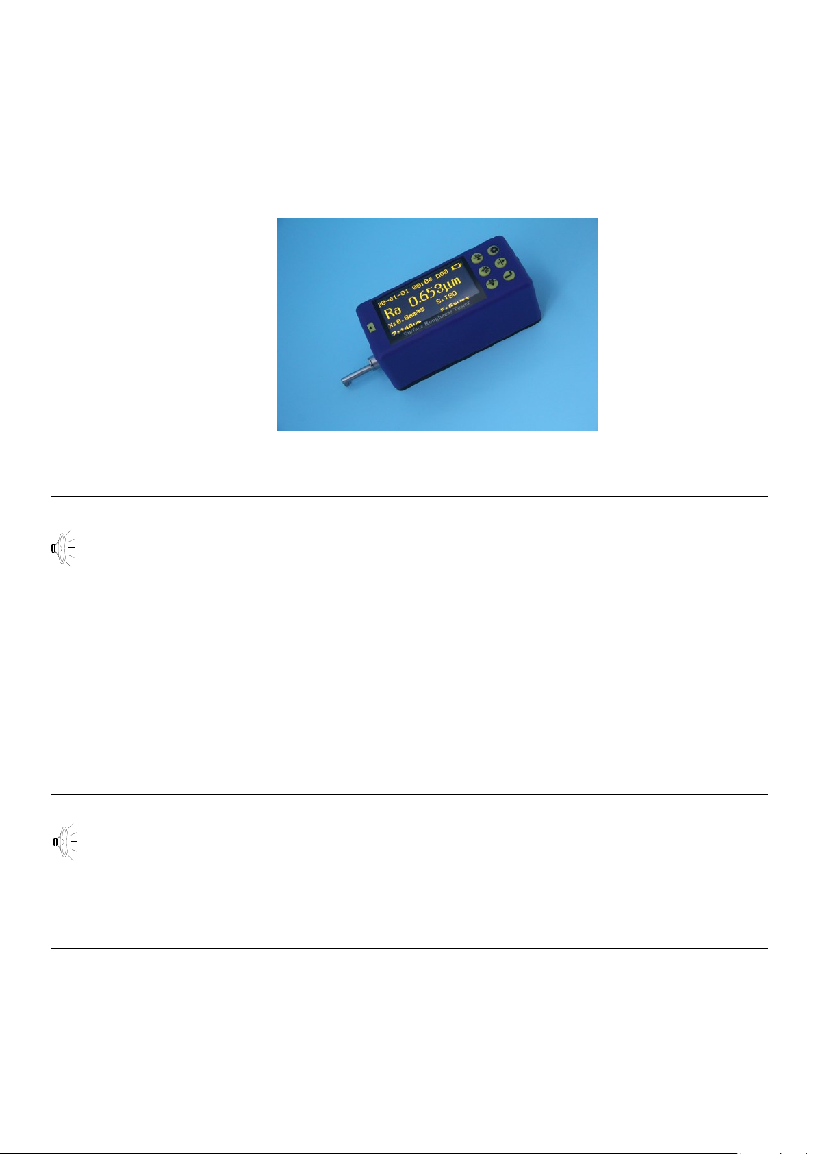
Main unit
Height support
Standard
pickup
Calibrate specimen
Pickup holder
Calibrate specimen
holder
Screw driver
Charger
Data cable
Parameters according to ISO
4287
Symbol
Arithmetic Mean Deviation
Ra
Root Mean Square Deviation
Rq
Maximum Height
Rz
Total Height
Rt
Max.Profile Peak Height
Rp
Max.Profile Valley Depth
Rv
Mean Width
RSm
Material Ratio
Rmr
Kurtosis
Rku
Core Roughness Depth
Rk
Reduced Peak Height
Rpk
Reduced Valley Height
Rvk
Material Portion
Mr1
Material Portion
Mr2
5
1.4Layout of the instrument
1.4.1 Main unit
1.4.2 Pickup

6
1.4.3 Display
1.4.4 Function of key
: Start: to start the measuring.
: Up/Parameter:
1, Press this button in the main screen to enter the Parameters screen, displaying all measurements of the
parameters. Press Set to exit;
2, After entering the other screens, the button will be set as the Up arrow.
: Down/Store:
1, Press this button in the main screen to enter the Record Storage screen;
2, After entering the other screens, the button will be set as the Down arrow.
: Left/Graphic:
1, Press this button in the main screen to enter Graphic screen, displaying various measurement graphics and
support rate curves etc;
2, After entering the other screens, the button will be set as the Left arrow.
: Right/Print:
1, Press this button in the main screen to start the wireless Bluetooth printer to print all measurements;
2, After entering the other screens, the button will be set as the Right arrow.
: Set/Menu:
1, Press this button in the main screen to enter fast Setting of measurement conditions, to set and change various
measurement conditions following the cursor;
2, Press and hold this button to enter the main menu;
3, After entering the other screens, the button will be set as Exit and Return in general.
: Return:
1, Press this button in the main screen to display the stylus position. Press this button again to exit the stylus
position;
2, In the other screens, press this button to confirming the setting/modification or exit this screen;
Note on arrows:
Function of Up/Down/Left/Right arrows: In screens other than the main screen: press Up/Down arrow to switch
and choose item; press Left/Right arrow to adjust the set number and value.
7
1.5Basic connection method
1.5.1 Assembling and dis-assembling of the pickup
As shown in the figure, hold the connection part of top guide tray and pickup main body (stylus is downward), plug
in the mainframe's connecting socket according to the figure connecting line direction, press lightly to the end till
stable connection. When taking out, please disconnect pickup from connecting socket, then take the pickup out
from drive slowly. All the operation process should be careful to avoid pickup breakage.
Assembling and dis-assembling of the pickup
Note: 1. Pickup stylus is the key accessory of this instrument, please pay high attention to it when using.
2. During the process of pickup assembling and dis-assembling, please do not touch the stylus to avoid
breakage which would affect the measurement.
3. During the process of pickup assembling, please make sure that the connection is reliable.
1.5.2 Charger and battery charging
When the battery is low on the display or the tester cannot boot, charge in time. To charge, connect the charger to
220V/50Hz mains power, and then connect the charger plug into the micro USB socket at back of the instrument,
charging will start. During charging, the LED (red) is ON; the LED (green) is ON after the battery is fully charged.
Disconnect the power. It takes about 3 to 4 hours to charge. The input voltage of charger is 100 ~ 240V, 50/60Hz
AC, maximum current: 0.2A; output 5V DC, maximum charging current of about 500 mA. This instrument uses a
lithium polymer battery, no memory effect. You can charge at any time, and the tester can work normally during
charging.
Note: 1.If measure on charging station, please make sure that the connecting cable's place would not affect the
measurement operation.
2.Please charge as soon as possible during the low voltage situation, and cut off power as soon as possible
after full charge.
3.The battery switch is off when the instrument leave factory.
4.If the instrument work in-properly, and turn off / turn on the machine cannot help to solve the problem, then
please turn off the battery switch of the instrument backside, and restart after 10seconds.
2 Setting for initial usage
To use this instrument for the first time, the Clock Setting screen appears after booting. Press Left/Right to move
between items. Press Up/Down to adjust the time. After setting, press Enter to confirm and exit. The clock setting
is complete.
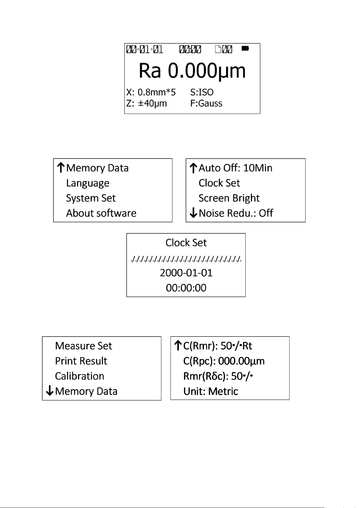
The following is the main screen, which appears after booting or before/after measuring. The main screen mainly
8
includes measurement parameters and various measurement conditions, such as sampling length, evaluation
length, range, filters and measurement units.
2.1Clock Setting
In main screen, press and hold Set button to enter the main menu. Select “System Set”and press Return to enter
System Set menu, then select “Clock Set” and press Return to enter Clock Setting screen.
In general, press Up/Down arrow to switch and choose the item; press Left/Right arrow to adjust the number.
2.2Units of measurement
In main screen, press and hold Set to enter the main menu; then select “Measure Set”and press Return. Press
Up/Down to select the Unit. Press Return to directly change the units of measurement. Press Set to exit.

9
2.3Language Select
In main screen, press and hold Set to enter the main menu. Press Up/Down and select “Language”. Press Return
to enter Language Select screen. Press Return to confirm and press Set button to exit.
3 Measurement Operation
3.1Preparation before measurement
a. Check the battery voltage after booting;
b. Wipe the surface of the workpiece to be measured with a soft clean cloth;
c. Keep the slide trace of the pickup perpendicular to machining texture of the measured surface of the
workpiece.
d. Keep the instrument and the pickup parallel with the measured surface during measuring.
e. During measuring, keep it away from vibration, magnetic fields, wind and other external environments which
will affect the measurements.
Measurement direction
Instruction: Correct and normative operation is the precondition to obtain precise measurement.
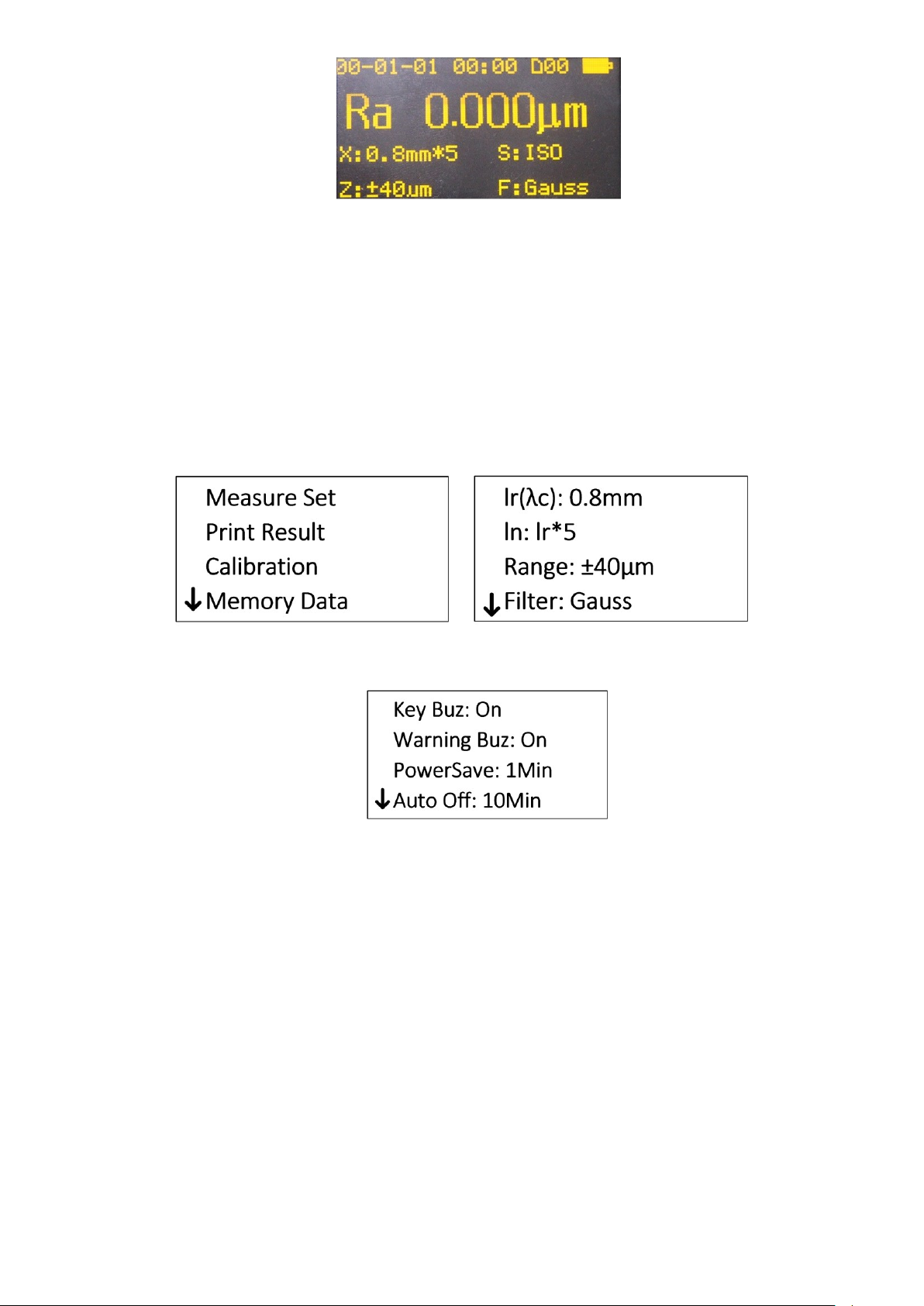
3.2Switch on
Starting up display
After booting, the default parameter settings, units of measurement, filter, range, sampling length etc will
automatically display, as shown in the following figure:

10
Instruction: The default setting will display after the first booting display, and the contents and measurements set by
the user prior to the previous shutdown will display after the next booting.
3.3Stylus position
In main screen, press Return button to check the stylus position of the pickup. In general, for measuring in the
plane, it is not necessary to adjust the position of the stylus. After measuring, the error of results is within the range
of the instrument.
The Stylus Position screen is used for the column, to adjust the height of the instrument up/down as required, in
order to determine whether the pickup has contacted the measured surface. The measuring may begin as the
point is near the zero point.
3.4Calibration
Before the measuring, calibration of the instrument using Calibration specimen is usually required. This instrument
is accompanied with a calibration specimen. Before the measuring, test the calibration specimen using the
instrument. Normally, as the difference between the measurement and the value of the specimen is within the
range of the instrument, the measurement is valid. It is unnecessary to adjust. The tester can be used for direct
measuring.
If the difference between the measurement and the value of the calibration specimen exceeds the range of the
instrument, or the user requires higher measurement accuracy, you can use the calibration function to correct the
measurements to improve the accuracy.
Calibration procedure:
In main screen, press and hold Set button to enter the main menu. Press Up/Down to select “Calibration”. Press
Return to enter Display Calibration Setting screen.
Press Up/Down to change the row. Select the desired range to calibrate. Press Left/Right to adjust the setting,
then press Return to confirm the change.
Estimate the value for correction depending on the error of the measurements. Input the measurement range and
11
then quit. Measure again and adjust, until the measurements are satisfied.
The calibration is subject to each range. Calibrate each range independently. The calibration results are stored in
the instrument's memory, which is not lost after shutdown.
Note: 1, To test the accompanying calibration specimen using proper measuring method, if the actual measurement
exceeds ±10% of the calibration value of the specimen, calibrate using the calibration function by the actual
error percentage with range less than ±20%.
2, In general, the instrument has been rigorously tested in the factory, and the display error is less than ± 10%. In
this case, it is recommended that users do not calibrate the tester frequently using the calibration function.
3, After the calibration value is set to “00” and confirmed, all calibration settings are clear to restore factory
settings.
3.5Getting Started
3.5.1 Start measuring
After completion of the above steps, you can start measuring. In the main screen, press the Start button to begin
measuring.
After sampling is completed, filtering of the sampled data starts.
After filtering is completed, all the parameters are calculated.
Tips: If you accidentally touch the power button in the measurement state, the instrument will be shut down. After
booting, the pickup will be reset. Do not intervene the pickup now. After resetting, the instrument is waiting for a
new start command.
3.6Result display
After measuring, all measurements can be observed in the following way:
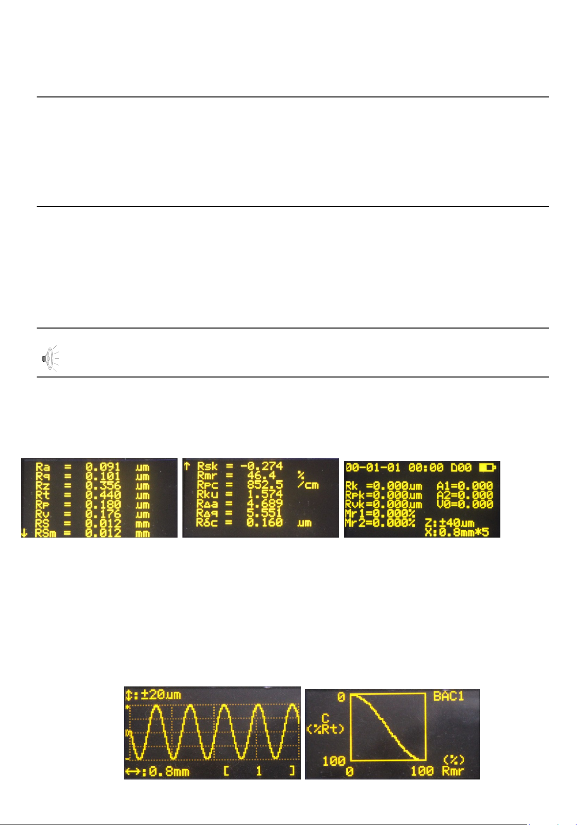
3.6.1 Parameters
In the main screen, press Up to enter all Parameters Display screen. Press Up/Down to PageUp/Down. Press Set
to return to the main screen.
3.6.2 Profile Graphic
In the main screen, press Left arrow to enter the Profile Graphic screen. A sampling length is displayed on each
page. Press Left/Right arrow to switch to other sampling lengths. In this screen, press Return to Zoom In/Out the
displayed profile. Press Set/Menu button to return to the main screen.
Press Up/Down arrow to switch to the Support Curve screen. Press Set/Menu button to return to the Profile
Graphic screen.

12
3.6.3 Store/read measurements
In the main screen, press and hold Set button to enter the main menu. Press Up/Down to select “Memory Data”.
Press Return to enter Memory Data screen.
1) Save current data
In the main screen, press Down arrow to directly enter the Store/Read screen. Press Up/Down arrow to store
current data. Press Return to enter the Store screen.
Press Return to confirm and store current data. You can modify the group No.
If the space is full, select delete in the “Memory Data” menu. Be careful for deleting data to avoid any mistakes. 20
groups of measurements can be stored.
2) Load history data
To load the history data, enter “Memory Data” menu, and then select “Load Mea. Data”. Find the desired group No.
Press Return to load the data.
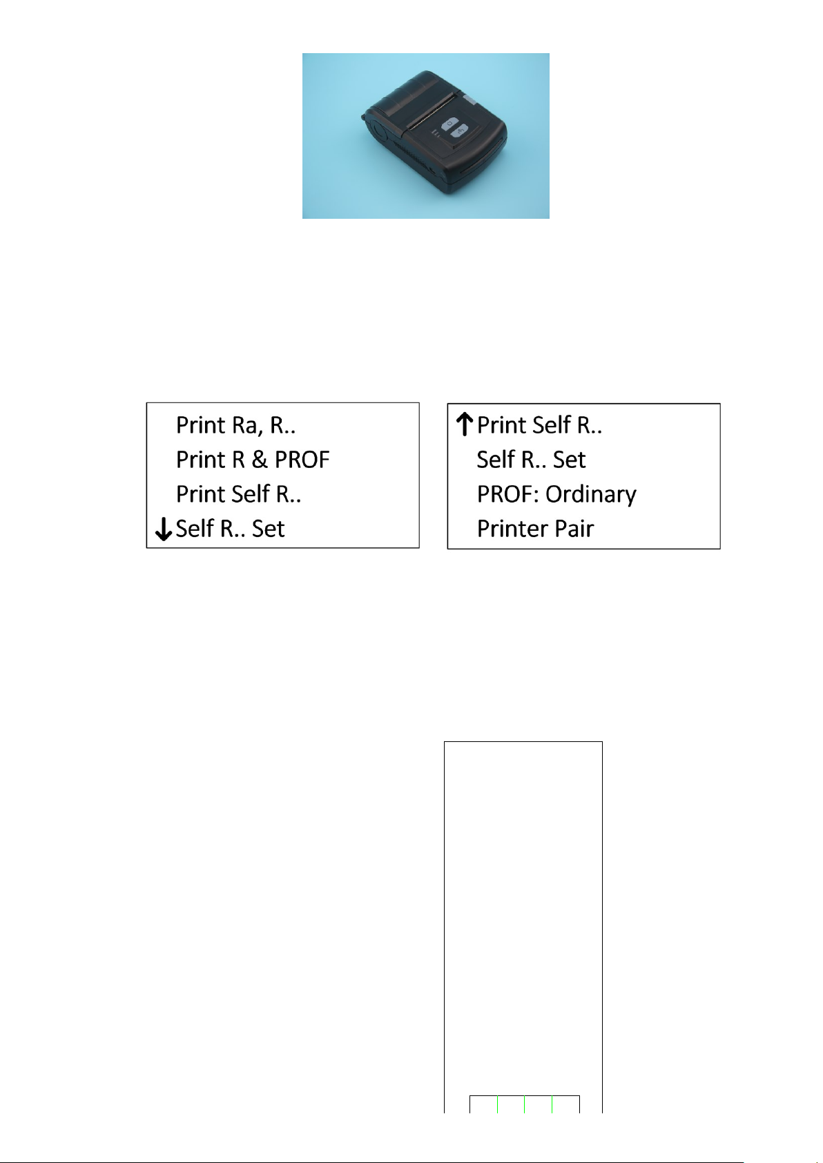
3.6.4 Print measurements
The instrument can be fit with optional wireless Bluetooth printer to print all measurements for filing.
13
After the measurement is complete, press Print button to print the measurements via the wireless Bluetooth
printer.
The contents to be printed can be set by the user. Enter the Menu Setting mode, then enter “Print Result”menu
item. You can select different presets, or customize the printing content to save time and paper.
Before printing, select a proper printer. First, install the optional printer, and turn on the power. Place the printer
near the PC. Then, select "Printer Pair" from "Print Results" menu item. Press Return to pair the printer and the
roughness tester. After about 3 seconds, display "Pairing successful". Press Set to return to the main screen and
you can print.
Print Setting screen
1) Start printing
In the main screen, press Right arrow to print the measurement parameters and profile graphics to the printer.
2) Paper
All printed contents.
SR200 Surface Roughness
Tester
Date 2008-01-01
Time 13:08:09
lr0.8mm
ln4mm
Filter Gauss
Ra μm
Rq μm
Rt μm
Rz μm
RSm mm
RS mm
Rv μm
Rp μm
Rz(JIS) μm
Ry(JIS) μm
RSk
R3z μm
Rmax μm
RPc /cm
Rmr(c1= μm) %
Rmr(c2= μm) %
Rmr(c3= μm) %
Rmr(c4= μm) %
Vv ×5000
Vh ×500
Ver. 2.0μm/10mm
Hor. 20.0μm/10mm
C

14
3.6.5 Connected with PC
The instrument can be fit with optional PC analysis software, which has database management, graphics display,
parameter display, measurement, print management, document management and other functions.
3.6.6 Remote measurement
This instrument has a remote controller to start the measurement. In certain cases, the stability of the
measurement can be improved.
Before using the remote controller, first match it. In the main screen, press and hold Set button to enter the Menu
Setting mode. Select “System Set”. Press Return to enter “System Set” menu item. Select “Remote Pairing”.
Press Return to pair the remote controller. After about 3 seconds, display "Pairing successful". Press Set to return
to the main screen and you can use the remote controller.
3.6.7 SD card
The instrument is equipped with an SD card for remote software upgrade.
Upgrade procedure:
1, Receive the new version of software from the manufacturer by e-mail;
2, Copy the software to the SD card; (insert the SD card into the USB port of PC via an adaptor).
3, Remove the SD card and insert it into the SD card slot at back of the instrument;
4, Start the tester and enter the main menu. Select "About Software". Press Enter button to enter the Upgrade
screen;
5, Select the “SW Update (mSD). Press Enter to start upgrading. You should wait a few minutes. When the
progress bar is full and flashing, the upgrade is complete.
6, Shut down and re-start.
4 Main Menu
In the main screen, press Set button to enter the main screen.
15
Main screen
4.1Measurement Condition Setting
There are two ways to set and modify the measurement conditions. One is fast setting, and the other is setting via
the menu.
The fast setting is used for brief and frequent modification during routine measurement to improve the efficiency.
In the main screen, press Set to enter fast setting mode. Follow the cursor, and press Up/Down/Left/Right arrow to
modify the corresponding measurement condition. Press Return to confirm and exit.
In the main screen, press and hold Set to enter Menu Setting mode. Select “Measure Set” to modify “Sampling
Length”, “Evaluation Length”, “Range”, “Filter”, “Standard”, “Parameters”, “C (Rmr)”, “C (RPc)”, “Rmr (Rδc)”, “Unit
of Measurement.
4.2System Setting
In the main screen, press and hold Set to enter Menu Setting mode. Select “System Set” to enter “System Set”
menu item. Under this menu, you can set the following contents:
Key Buz
Warning Buz
Power saving time
Auto power off time
Clock Setting
Low-noise measurements
Screen test
Remote controller paring
Surface type selection
Press Return to confirm and exit.
4.3Software information
The software information contains the model of the instrument, software version, the serial number and the
identification No
16
5 Routine Maintenance and Care
5.1Pickup
1) After measuring, put the pickup into the box in time;
2) Protect the stylus of the pickup;
3) The pickup is a key component to acquire the measurement signal, precise, sensitive and fragile. Handle
carefully.
5.2Host
1) Keep the surface clean. Clean with a soft dry cloth to remove the dust;
2) The instrument is of precision testers. Handle it carefully to avoid serious vibrations, or damage thus occurred.
5.3Battery
1) Check the battery frequently. Charge in time if the battery is low;
2) The charging time is about 3 to 4 hours;
5.4Calibration specimen
1) Keep the surface clean;
2) Avoid scratching the calibration specimen work area surface and leading to wrong calibration.
6 Common Faults
7 Accessories
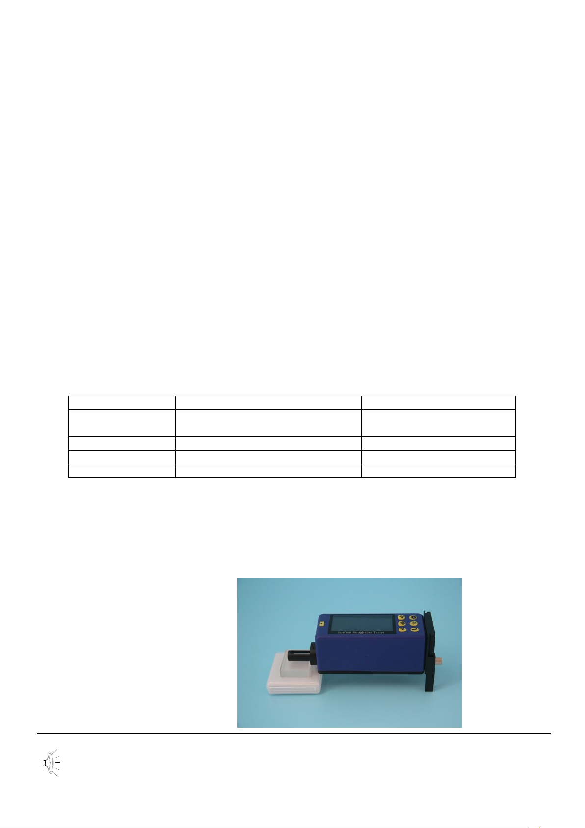
7.1Height support and pickup holder
When the measured surface of the workpiece is smaller than the bottom surface of the instrument, you can use
the pickup holder and height support in the following optional accessories to support to complete the
measurement (as shown below).
Height support and pickup holder
Tips: 1. The dimension L in Figure 1 cannot be less than the driving stroke of the measurements to avoid that the
pickup falls outside the workpiece during measuring, causing malfunctioning of the workpiece as the pickup
returns against the workpiece.
Faults
Reasons
Measures
Over range
The pickup and the body not parallel
with the surface to be measured
Switch to large range
Adjust stylus position
No test data
No measuring after booting
Measure again
Motor problem
Driver blocked
Measure again
Error during running
Abnormal interruption
Re-start
17
2. The height support must be locked reliably.
3. Do not adjust the stylus position using the height support during measuring. Adjust the adjustable feet to the
desired height before measuring. Measure with calipers to meet the requirements.
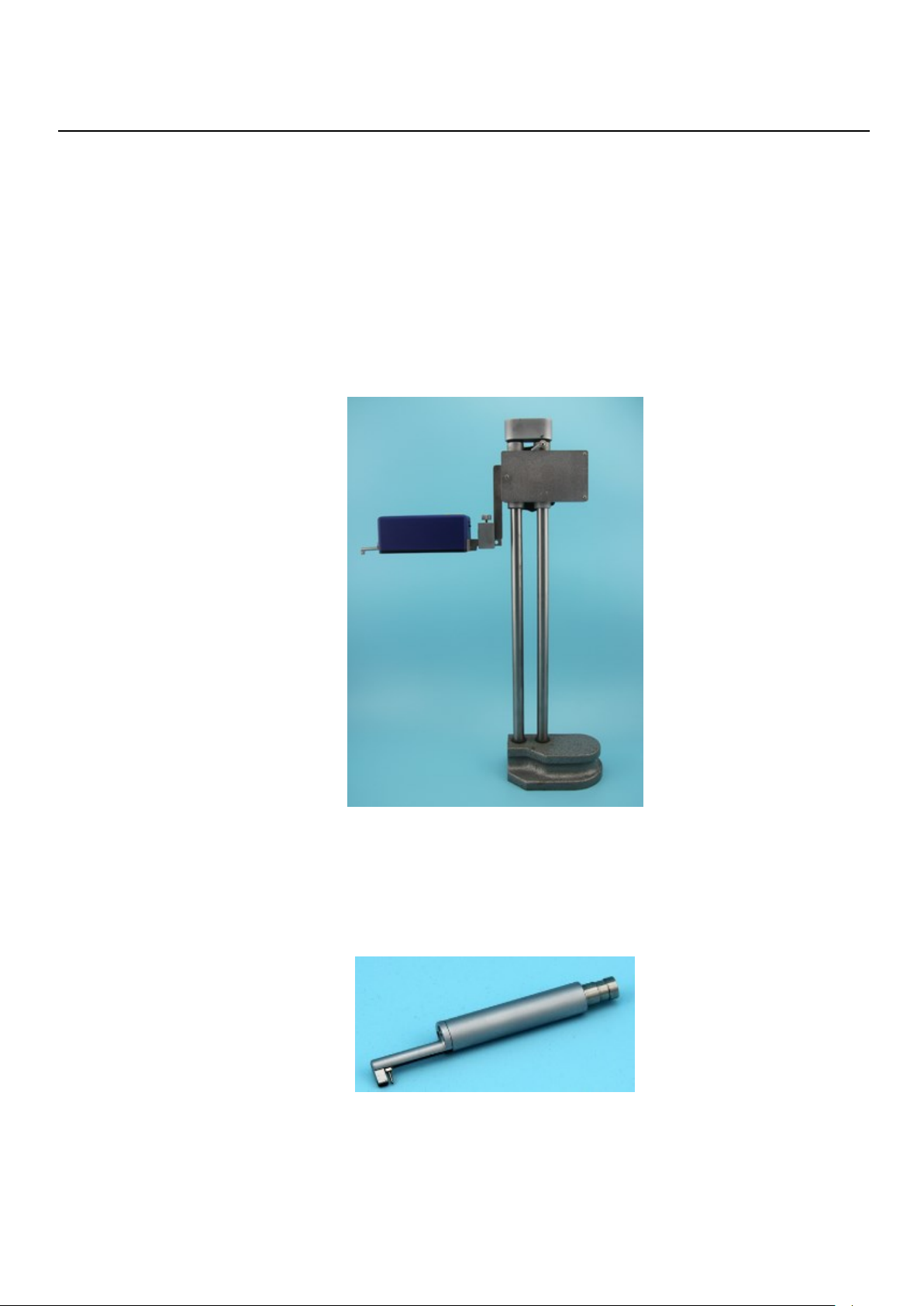
7.2Height stand
Use a height stand to adjust the position between the instrument and the workpiece more accurately for more
reliable and stable operation, to expand the measuring space and measure larger workpieces. To use a height
stand, be careful as the pickup is close to the workpiece, so as to avoid damage to the pickup due to malfunction.
When the pickup is close to the workpiece surface, check the stylus position on the screen carefully. It is OK as the
pointer stays in the middle of the display. When the Ra value of the measured surface is small, it is recommended
to use the measurement platform. Start the measurement with a remote controller in order to reduce the impact of
the external environment on the measurements. To use special pickups, such as aperture, deep groove and
curved surface pickups etc., use the column height ruler height gauge or other adjustment equipment.
Height stand
7.3Standard pickup
The standard pickup is used more, which can measure the roughness of the most flat, slope, conical surfaces,
inner holes, grooves and other surfaces. Handheld measurement is available. Except for standard pickups, the
measuring platform is required for other pickups.

18
7.3.1 Size
Size
7.3.2 Operating instructions
1) Handheld measurement
After inserting the pickup into the instrument, measure directly on the surface of the workpiece. In addition to
setting the correct measurement conditions, make sure to: keep the body of the pickup level; keep the pickup
sliding direction perpendicular to the texture of workpieces.
2) Use height stand
See the picture of height stand in section 7.2.
a. Insert the standard pickup carefully into the instrument, and then mount it on the column connectors. Lock
reliably;
b. Adjust the column carriage slightly higher. Lower it until the pickup contacts the workpiece. Be careful,
especially as the pickup contacts with the workpiece.
c. Adjust the body of pickup level and check visually. Check whether the stylus position is near the center.
d. Lift the pickup in proper direction. Wrong direction will cause damage to the pickup.
7.3.3 Calibration
1) Measure the multi-line specimen;
2) Read the Ra value;
3) Compare it with the calibration specimen.
7.3.4 Precautions
1) Be careful to plug the pickup. Do not touch the guide and the stylus, which are key parts of the instrument.
Try to hold the base of the pickup guide bracket (front body);
2) 2) After operating the pickup, place it in the package.
7.4Curve surface pickup
Curve surface pickups are used to measure the roughness of smooth cylindrical surface with a radius greater than
3mm. Perfect approximation value can be achieved for spherical surfaces with larger radius of and other smooth
surfaces, the greater the radius of curvature, the smoother the surface, the better the measurement.
19
7.4.1 Size
7.4.2 Operating instructions
1) Insert the curve surface pickup carefully into the instrument, and then mount it on the column connectors.
Lock reliably;
2) To use the pickup surface, select a shorter trip as possible, such as: 0.25 sampling level, especially for
small arc;
3) Adjust the column carriage slightly higher. Lower it until the pickup contacts the workpiece. Be careful,
especially as the pickup contacts with the workpiece;
4) Keep the stylus of the pickup aligned with the highest (or the lowest) point of the quasi curve surface;
5) Adjust the body of pickup level and check visually. Check whether the stylus position is near the center.
7.4.3 Measurement
Before measurement, move the workpiece right to half of the travel. Press Start to start measurement. This is to
ensure that the entire measurement travel is symmetry taking the highest point (the lowest point) of the surface as
the center.
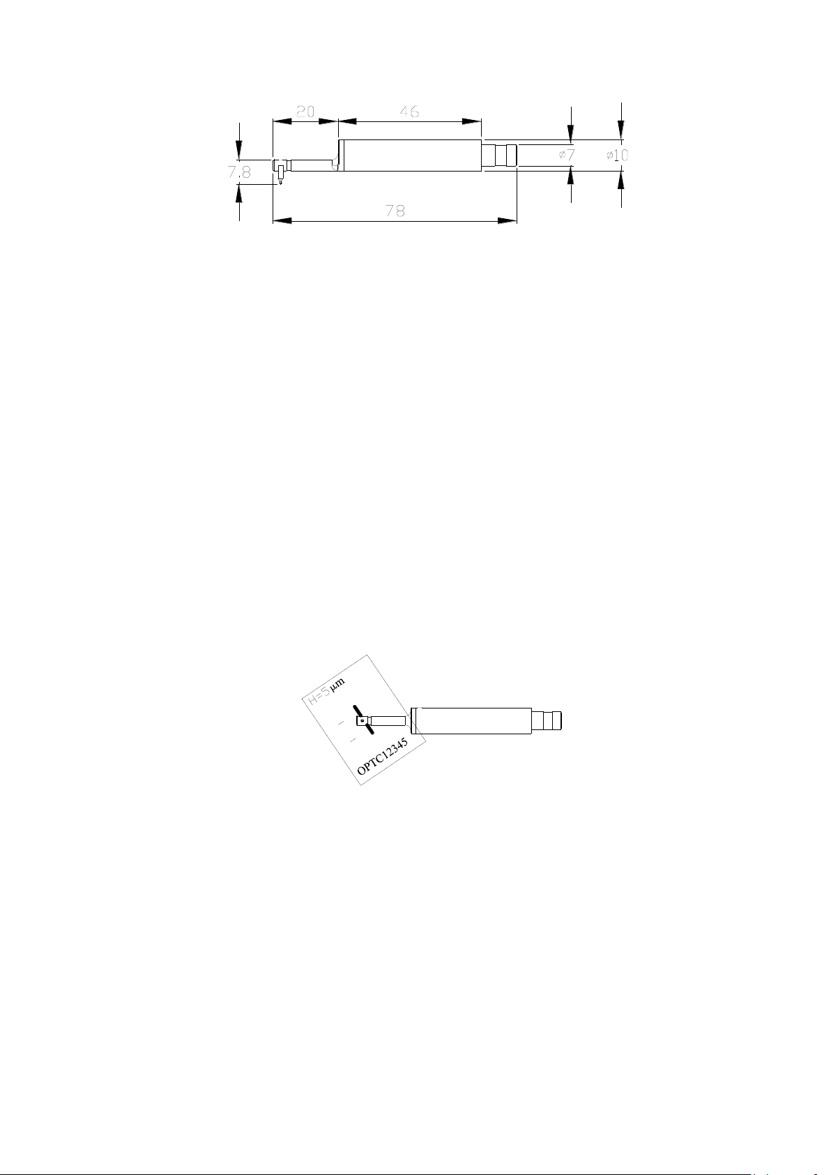
7.4.4 Calibration
1) Calibrate the curve surface pickup using a single-line specimen;
2) Calibrate.
Calibration
As shown in the figure, incline the single-line model at certain angle, so that the guide and the stylus pass the line
in order rather than at the same time (which is not the true depth). After measuring, observe the profile graphics.
There is a rectangular deep groove, and the groove depth is the single-line value. There are several methods to
read the depth of model:
a. Read the Rt value, which may be inaccurate as the location is not proper;
b. Measure this depth with the mouse using the software;
c. Measure the actual depth of the outline on the printer, divided by the magnification.
7.4.5 Precautions
1) Be careful to plug the pickup. Do not touch the guide and the stylus, which are key parts of the instrument.
Try to hold the base of the pickup guide bracket (front body);
2) The main difference between curve surface pickups and other pickups is that its guide and the stylus are
parallel, and those for other pickups are in tandem;
3) The curve surface pickup cannot be calibrated using a multi-line calibration specimen due to its structure.
Table of contents
Other BMS Test Equipment manuals


Popular Test Equipment manuals by other brands


Redtech
Redtech TRAILERteck T05 user manual

Venmar
Venmar AVS Constructo 1.0 HRV user guide

Test Instrument Solutions
Test Instrument Solutions SafetyPAT operating manual

Hanna Instruments
Hanna Instruments HI 38078 instruction manual

Kistler
Kistler 5495C Series instruction manual

Waygate Technologies
Waygate Technologies DM5E Basic quick start guide

StoneL
StoneL DeviceNet CK464002A manual

Seica
Seica RAPID 220 Site preparation guide

Kingfisher
Kingfisher KI7400 Series Training manual

Kurth Electronic
Kurth Electronic CCTS-03 operating manual

SMART
SMART KANAAD SBT XTREME 3G Series user manual

Agilent Technologies
Agilent Technologies BERT Serial Getting started