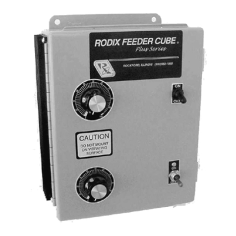
Precision Governors E-611 User manual

PG
ENGINEERED CONTROL
SOLUTIONS
ELECTRIC GOVERNOR
INSTALLATION MANUAL
Precision Governors E-611 Multipurpose
Controller.
E-611A with Terminal Strip P/N 9078
E-611B with 8 pin Plug P/N 9077

Precision Governors, LLC
1715 Northrock Ct
Rockford, IL 61103
Ph: 815-229-5300 Fax: 815-229-5342
www.pgcontrols.com
PG ENGINEERED CONTROL SOLUTIONS
ENGINEERED CONTROL SOLUTIONS
INTRODUCTION:
The E-611 controller is a general-purpose controller intended to control
engine speed for spark ignited or diesel engines. It is intended to feature more robust speed
regulation over the E-301 and E-361 products when retrofitted to system using other brands of
controllers and low resistance low current actuators.
For spark-ignited engines it may be configured to sense engine speed via ignition system frequency.
For both spark ignited and diesel engines, it may be configured to sense engine speed via magnetic
pickup sensing flywheel teeth.
The E-611 controller may be configured to govern speed in either discrete mode where the application
can select 1 of 4 speeds or it can be configured to operate in “ramp mode” where the controller has a
“increase speed” and a “decrease speed” input. This is similar to cruise control.
The E-611 controller requires no computer adjustments by the user. It features speed and gain
adjustments via potentiometer and governing style and speed signal frequency range determined by
setting of an 8 position DIP switch.
Discrete governing features 4 independent speed settings from 1000 to 3400 RPM.
Ramp governing features independent minimum, maximum, and initial ( engine off) speed settings
and a set speed ramp rate.
All governing modes feature gain, integral, and derivative adjustments.
The E-611 controller is 12 and 24 volt compatible. It is reverse polarity protected.
GENERAL
The following information is intended as an aid to properly installing a Precision Governors Model E-
611. Since these governors are used on a wide range of engines in many different applications, much
of the information is somewhat general in nature. If you need assistance concerning a specific detail
on your application, please consult Precision Governors Application Engineering at 815/229-5300.
These instructions presume no electrical test equipment other than a Multimeter for making the
electrical measurements called for on the following pages. If no meter is available, inexpensive but
adequate meters, are available from many consumer electronics stores such as Radio Shack.
Many "governor problems" turn out to be installation problems, particularly in first-time applications.
Careful attention to the directions provided will go far toward a successful installation made in the least
amount of time.
The E-611 is available with a 8 pin terminal strip ( E-611A) or with a 8 pin Packard Disconnect ( E-
611B.
QUICK-START INSTRUCTIONS
If you are experienced in installing and adjusting Electric Governors, follow these steps. Otherwise,
refer to the more detailed instructions, which begin on Page 8, starting with "Governor Assembly.”
1) Mount Controller in a dry, fairly cool location. Accessibility for adjusting is required.

Precision Governors, LLC
1715 Northrock Ct
Rockford, IL 61103
Ph: 815-229-5300 Fax: 815-229-5342
www.pgcontrols.com
PG ENGINEERED CONTROL SOLUTIONS
ENGINEERED CONTROL SOLUTIONS
2) Wire per the appropriate system schematic. BE SURE TO OBSERVE CORRECT POLARITY.
Note some wire locations are different than the original controller.
3) Set the machine to command the various speeds and adjust. Turn CW to increase speed, CCW
to decrease speed.
4) Set Gain as required, using Gain pot. CW increases sensitivity. Load and unload the engine to
check for proper gain.
CARBURETOR IDLE ADJUSTMENT
Engines with Integrated actuator / carburetor:
For carburetors with no idle adjustment stop screw, the mechanical idle is adjusted by disconnecting
the actuator wires then loosening the 3 actuator mounting screws and turning the actuator to obtain
the desired idle speed. This should be set with a fully warmed up engine and hydraulic system. This
setting must be at least 100 RPM below the lowest governed speed. Setting this too low may cause
the engine to stall during operation while setting this too high may create delays in engine governing or
cause the engine to continue running after power has been removed. Tighten the screws. After
turning off the engine, reconnect the actuator. Failure to turn off the engine may result in the engine
over-speeding.
Engines with separate actuator / carburetor:
Engines with separate actuator / carburetor should have the mechanical idle set by disconnecting the
actuator wires and adjusting engine speed with the carburetor stop screw. This should be set with a
fully warmed up engine and hydraulic system. This setting must be at least 100 RPM below the lowest
governed speed. Setting this too low may cause the engine to stall during operation while setting this
too high may create delays in engine governing or cause the engine to continue running
after power has been removed. Tighten the screws. After turning off the engine, reconnect the
actuator. Failure to turn off the engine may result in the engine over-speeding.
Diesel Engines:
Diesel engines typically have speed regulated electronically via an actuator controlling the fuel shutoff
lever or rack. On these engines, the mechanical governor should be set ABOVE the maximum
desired governed engine speed by 10% or more as speed can only be reduced by the electronic
governor.
MOUNTING--CONTROLLER
The replacement controller will require new mounting holes to be drilled.
The controller is water and weather resistant when the cover plate is filleted with RTV by the user.
However, attention to the following points will enhance its performance and reliability:
Select a reasonably cool, dry, and vibration free location.
The rear cover will probably need to be removed during set-up in order to make adjustments for
speed-setting and gain. You may wish to defer final installation until this is done.
After completing these adjustments, replace cover, and seal with a finger-fillet of RTV. Mount so
that water cannot pool on this cover. Mounting with this cover out of sight discourages "fiddling.”

Precision Governors, LLC
1715 Northrock Ct
Rockford, IL 61103
Ph: 815-229-5300 Fax: 815-229-5342
www.pgcontrols.com
PG ENGINEERED CONTROL SOLUTIONS
ENGINEERED CONTROL SOLUTIONS
WIRING
CAUTION:
Improper hook-up can damage electronics. Re-check wiring before applying power.
When retrofitting another manufacturer’s controller:
For retrofitting Barber Coleman controllers with terminal strips, wires may need to be moved.
For retrofitting Barber Coleman controllers with an 8-pin plug, the E-611 should not need any wiring
changes.
E-611A:
See Figure 1 for the controller wiring changes.
The original controller wires on pins 3 and 4 must be moved to the E-611 pins 5 and 6 (the order
is not important)
The original controller wires on pins 5 and 6 must be moved to the E-611 pins 3 and 4 (the order
is not important). Note, the controller does NOT use pin 4 but this pin is provided to fasten an
existing second DIS speed signal wire to an isolated pin. DO NOT short both speed signal wires
together.
Wires attached to pins 1, 2,7, and 8 of the original controller governor should be connected to the
same pins on the E-611.
If the machine had a wire connected to pin 9 of the Barber Coleman governor, this wire should be
connected to pin #1 of the E-611 in addition to the original power wire. This pin is simply a +
battery supply for the speed select switches.
E-611B Wiring:
Refer to Figure 2for pin functionality. E-611B terminal “A” corresponds to E-611A pin 1,
terminal “B” to pin 2, terminal “C” to pin 3,etc. Again, the E-611B does not require wiring
modifications.
A properly functioning 12 volt engine electrical system will supply 13.5-14.8 VDC when the engine is
running. If wiring size is adequate, with good connections and proper grounds, you will get this reading
between the wires to terminals 1 & 2 of the 8 pin terminal strip when the Governor is controlling engine
speed. Verify this.

Precision Governors, LLC
1715 Northrock Ct
Rockford, IL 61103
Ph: 815-229-5300 Fax: 815-229-5342
www.pgcontrols.com
PG ENGINEERED CONTROL SOLUTIONS
ENGINEERED CONTROL SOLUTIONS
Figure 1 E-611A Retrofit Wiring
Distributor less Engine Wiring:
For use with distributor less engines, the controller’s speed signal inputs are connected to the DIS
ignition module coil output wires. Refer to engine schematics for the engine’s ignition wiring.
Normally these signals are the outer 2 leads (pins 1 and 3) of the coil pack 3 pin connector. Refer to
Figure 2: DIS wiring for the basic governing wiring schematic.

Precision Governors, LLC
1715 Northrock Ct
Rockford, IL 61103
Ph: 815-229-5300 Fax: 815-229-5342
www.pgcontrols.com
PG ENGINEERED CONTROL SOLUTIONS
ENGINEERED CONTROL SOLUTIONS
Figure 2: DIS wiring
Distributor Engine Wiring:
For use with distributor engines, the controller’s speed signal A input is connected to the ignition coil
NEGATIVE lead. Refer to Figure 3: Distributor Engine Wiring for the basic governing wiring
schematic.
Figure 3: Distributor Engine Wiring
Diesel Engine or spark ignited engine using a mag pickup:

Precision Governors, LLC
1715 Northrock Ct
Rockford, IL 61103
Ph: 815-229-5300 Fax: 815-229-5342
www.pgcontrols.com
PG ENGINEERED CONTROL SOLUTIONS
ENGINEERED CONTROL SOLUTIONS
For engines utilizing a magnetic speed pickup, the mag pickup has one lead connected to ground and
the other to the controller’s speed signal A terminal. The mag pickup ground lead should be as close
to the controller’s ground terminal as feasible to minimize electrical noise. Refer Figure 4: Mag Speed
Pickup Wiring for the basic governing wiring schematic.
Figure 4: Mag Speed Pickup Wiring
CONTROLLER INITIAL SETUP:
The E-611 controller requires a DIP switch to be configure to select the proper engine speed signal
type and frequency ratio. It additionally can be configured to operate as either a fixed speed where it
runs 1 of up to 4 different speeds based on 2 speed select inputs OR operates as a cruise control
where the user can ramp the speed up or down with momentary contact faster / slower input
switch(s). Refer to Figure 5for the location of DIP switches and adjustments.
Controller power MUST Be removed and reapplied for DIP switch changes to be used. If it is
changed during operation, any changes will NOT take effect until controller power is cycled
OFF and back ON.
Potentiometer adjustments take effect immediately.
The controller is initially configured for a 4 cylinder distributor less engines using in discrete governing
mode. All DIP switches will be in the OFF position.

Precision Governors, LLC
1715 Northrock Ct
Rockford, IL 61103
Ph: 815-229-5300 Fax: 815-229-5342
www.pgcontrols.com
PG ENGINEERED CONTROL SOLUTIONS
ENGINEERED CONTROL SOLUTIONS
For 4 cylinder DISTRIBUTOR-LESS engines, set DIP switches 1-7 OFF.
For 4 cylinder DISTRIBUTOR engines, set DIP switch 1 ON and switches 2-7 OFF.
For 6 cylinder DISTRIBUTOR engines, set DIP switch 2 ON and switches 1 and 3-7 OFF.
For 8 cylinder DISTRIBUTOR engines, set DIP switch 1 and 2 ON and switches 3-7 OFF.
For other speed inputs, refer to the speed range adjustment in Figure 5.The controller needs to
know the speed pickup frequency to engine speed ratio to obtain the correct speed range. Diesel
engines typically have between 90 and 130 flywheel teeth ( Pulses / Rev). If in doubt, select a lower
pulse per rev setting and change to a higher setting if engine speed cannot be adjusted high enough.
The mag pickup frequency can be measured and compared to the high and low limits in the table.
CHECK-OUT &INITIAL START-UP PROCEDURES
As machines have different speed settings and wiring differs between machines, consult machine
service manuals for machine specific wiring, speed settings, and methods to command each set
speed. Precision Governors does not have information as to how particular machines are configured,
wired, or the proper speed settings.
Assuming that the Governor Assembly and Controller are mounted and the wiring is run and checked,
proceed as follows:
1) Set DIP switch to the desired governing mode and proper pulse per Rev count.
2) Turn ignition switch on. Do not start engine. The throttle actuator should not be powered when
the engine is NOT running.
3) Use a Multimeter to check battery voltage at battery terminals, and record. Now check voltage at
the machine connection points for terminals 1 & 2 ( 1 is +, 2 is - ).This voltage reading should be
the same as at battery. If not, shut down, and correct wiring.
4) Before proceeding, familiarize yourself with the locations of the Speed adjustment pots and the
Gain, Integral, and Derivative Pots, see Figure 5. Read the section on Adjustments.
5) Start engine then set machine controls as necessary to adjust all applicable set speeds. If engine
speed surges or is not stable, reduce Gain and / or adjust integral and derivative as needed.
6) Re-check voltage between the connections for terminals A & B as in step 2. Voltage reading
should be between 13.5--14.6 VDC. If less, look for undersized wiring somewhere in the system,
or for other components wired in parallel with the Governor.
7) Carefully adjust Gain. You are looking for the best compromise between quick response and
good stability. Make very small adjustments, then load and unload engine. Usually, a good set-up
is one that makes 1 to 3 small bounces and then steadies down after a large load change. Too
much Gain shows up as a rapid (once per second) instability, most commonly at light loads. Too
little Gain shows up in large over-shoots on start-up or large load changes, and generally sluggish
operation. A good initial setting for the gain is to turn fully counterclockwise and then turn
clockwise 3/8 of a turn. Changing the gain may affect the set speed.
8) Integral Adjustment. This adjustment is typically not critical for most applications. A good initial
setting for the integral is to turn fully counterclockwise and then turn clockwise 1/2 of a turn. This
adjustment affects how long the controller takes to completely recover from a load change. If,
after applying a load, the engine recovers below set speed then creeps up to the set speed over

Precision Governors, LLC
1715 Northrock Ct
Rockford, IL 61103
Ph: 815-229-5300 Fax: 815-229-5342
www.pgcontrols.com
PG ENGINEERED CONTROL SOLUTIONS
ENGINEERED CONTROL SOLUTIONS
several seconds, this adjustment may be increased. If, after a load application, the engine
recovers to a speed above set speed and then creeps down to the set speed, this adjustment may
be decreased. Setting this too high may also introduce a slow engine speed wander at lower
engine speeds or load factors. Changing the integral will affect the set speed. Note, the Integral
has previously been referred to as “factory set” in Precision Governors literature.
9) Re-install the back cover on the control unit. Add a finger fillet of RTV around the edge of this
cover to seal against dirt and moisture. Final-mount the controller.
GOVERNOR ADJUSTMENTS
Adjustment Ranges:
Speed Adjustments: The discrete speed settings and up/down speed settings all have a range of 1000
to 3400 RPM. 1000 RPM corresponds to fully counterclockwise while 3400 RPM corresponds to fully
clockwise.
Gain and speed rate adjustments are low at counterclockwise and high when clockwise.
All adjustment potentiometers have about ¾ rotation of adjustment. Forcing them beyond this may
damage the adjustment.
Adjustments for each Governing Mode:
Discrete Mode:
For “Discrete” governing mode where the controller chooses 1 of up to 4 fixed engine speeds, set DIP
switch #8 OFF (Default).
Discrete Governing Speed Adjustments:
Discrete governing mode allows for up to 4 different set speeds based on the voltage applied to inputs
1 and 2. Each speed adjustment is independent of the other and can be set above, below, or the
same as any other speed adjustment.
The adjustment for each combination of input pins 1 and 2 can be found in Table 1and can be
determined by commanding each speed from the machine and either measuring for voltage on pins 1
and 2 or counting the blinks of the controller’s diagnostic LED and finding the appropriate adjustment
pot from the table below.

Precision Governors, LLC
1715 Northrock Ct
Rockford, IL 61103
Ph: 815-229-5300 Fax: 815-229-5342
www.pgcontrols.com
PG ENGINEERED CONTROL SOLUTIONS
ENGINEERED CONTROL SOLUTIONS
Input
1
2
Discrete Governing Mode: DIP SWITCH 8 OFF
Terminal
8
7
Pigtail
Pin
H
G
Blinks
Color
Green
Orange
Adjustment
Pot
E-361
Setting
E-301
Setting
Engine
Running
Engine
Off
0
0
1
1400
2800
1
5
Level
12
0
2
1800
2200
3
7
0
12
3
2200
1800
2
6
12
12
4
2800
1400 ?
4
8
Table 1: Discrete Governing Speed Settings
Ramp –UP/DOWN Mode:
For “Ramp” or “UP / DOWN” governing mode where the controller has a variable speed controlled by
“faster” and “Slower” inputs, set DIP switch #8 to ON. Speed related adjustments for UP / DOWN
mode are detailed in Table 2.
Minimum Speed:
The minimum speed is set with adjustment P1. While the engine is running, the minimum speed can
be set by continually requesting engine speed DOWN and adjusting P1.
Maximum Speed:
The maximum speed is set with adjustment P2. While the engine is running, the maximum speed can
be set by continually requesting engine speed UP and adjusting P2. Note, Maximum speed should be
set ABOVE the minimum speed.
Initial (Startup) Speed:
While the engine is running, the initial speed can be set by continually holding BOTH UP and DOWN
and adjusting P3. If normal machine wiring does not allow this, it may be necessary to apply +12v to
both UP and DOWN separately from the machine. It is up to the user to determine the most feasible
manner of doing this.
Ramp Rate:
For UP / DOWN mode, the user can adjust how fast the set speed changes with P4. Turn P4
clockwise to change speeds faster and counter clockwise to change speeds SLOWER.

Precision Governors, LLC
1715 Northrock Ct
Rockford, IL 61103
Ph: 815-229-5300 Fax: 815-229-5342
www.pgcontrols.com
PG ENGINEERED CONTROL SOLUTIONS
ENGINEERED CONTROL SOLUTIONS
Input
1
2
UP / Down Governing Mode: DIP SWITCH 8 ON
Terminal
8
7
Pigtail
Pin
H
G
Blinks
Color
Green
Orange
UP / Dn
Function
Adjustment
Pot
Engine
Running
Engine
Off
0
0
No Change
1
5
Level
12
0
Decrease
1
3
7
0
12
Increase
2
2
6
12
12
Initial Spd
3
4
8
Speed Change Rate
Pot P4
Minimum
62
rpm per second
Maximum
3000
rpm per second
Table 2: UP Down Governing Adjustments
Gain Adjustments:
The controller has 3 gain adjustments that are used to obtain the fastest and most stable engine
speed control. Increasing each component will cause the controller to respond faster and more
aggressive. Higher gain values will
P5 adjusts the overall gain (Master Gain) of the controller.
P6 adjusts the derivative gain.
P7 adjusts the integral gain.
GAIN COMPONENTS:
Gain settings control how aggressively the controller attempts to change fueling in order to
maintain engine speed. Too little gain results in sluggish response while too much gain results in
an engine that does not maintain a constant speed.
The controller uses 3 types of adjustments to maintain the desired engine speed:
Proportional Gain
This is a correction that is directly related to how much the engine is above or below the desired
set speed. Proportional gain does not consider how fast the engine speed changes or how long it
has been away from the desired speed. Proportional gain will correct for a portion of the error but
may result in the engine turning too fast or too slow. Excessive proportional gain can cause the
engine to have jitter in the engine speed and /or vibrate. Too low of a proportional gain will cause
slow recovery to load changes. In some engine families, too low of gain may result in slow speed
wanders. For this controller, Proportional is fixed and the master gain should be used to adjust
this portion.
Integral Gain
This is a “long term” correction that adds up the error over time. It is used to get the engine to the
exact set speed. The integral adjustment changes how long it takes to get back to the set speed
after a load change. Excessive integral will cause the engine to pass the set speed then creep
back to the set speed. Excessive integral will often cause the engine speed to go up and down

Precision Governors, LLC
1715 Northrock Ct
Rockford, IL 61103
Ph: 815-229-5300 Fax: 815-229-5342
www.pgcontrols.com
PG ENGINEERED CONTROL SOLUTIONS
ENGINEERED CONTROL SOLUTIONS
once every 2-10 seconds. Too low of an integral setting will cause the engine to creep to the set
speed without first crossing it.
Derivative Gain:
This is a correction that is applied as the engine changes speed. If the engine quickly slows in
speed, the derivative will cause an immediate increase in fuel. If the engine quickly increases in
speed, the derivative will cause an immediate decrease in fuel. If the engine is not changing
speed, the derivative will not affect the fuel request. Some engines respond well without any
derivative. Some engines require derivative gain to stabilize. Too high of a derivative may show as
a quick oscillation (1 or more times per second) in engine speed or a random changes in engine
speed. High derivative settings can slow the normal recovery to load changes.
Master Gain:
This is an overall factor applied to the proportional, derivative, and integral components. This is
typically assigned to an adjustment pot so that the whole system can be made more or less
aggressive with one adjustment. The integral and derivative can be adjusted to obtain the optimal
balance of proportional, derivative, and integral gain.
Rough Gain Adjustment:
Turn the gain up until the engine gets unstable –it will quickly randomly change speeds, shake,
and / or vibrate.
Reduce the gain until the engine stabilizes.
(If the engine will not stabilize or wanders, attempt to stabilize the engine with the derivative.)
Rough Derivative Adjustment:
Increase the derivative until the engine has a fast oscillation to it, that is more than 1 per second.
Decrease the derivative until the engine stabilizes. For some applications, the system will provide
optimal response with the derivative set to minimum. Some applications will not be stable without
derivative. Many systems will show improved stability with some derivative.
Rough Integral Adjustment:
Increase the integral until the engine has a 2-10 second speed pulsation. Reduce the integral so
that the engine stabilizes. If, upon adding a large load, the engine speed drops, goes above set
speed as the governor responds, then wanders down slowly, reduce the integral. If the engine
drops, recovers to a speed below the set speed then creeps up to the set speed, increase the
integral.
Diagnostic LED:
The controller has a diagnostic LED. This blinks a code from 1 to 8 blinks followed by a pause.
The LED indicates: If engine speed is measured on the speed input and the status of inputs 1 and 2.
Refer to Table 1and Table 2 for blink codes. This also allows the technician to determine the proper
speed adjustment to use for the present combination of inputs.

Precision Governors, LLC
1715 Northrock Ct
Rockford, IL 61103
Ph: 815-229-5300 Fax: 815-229-5342
www.pgcontrols.com
PG ENGINEERED CONTROL SOLUTIONS
ENGINEERED CONTROL SOLUTIONS
Figure 5: Controller Adjustments and DIP switch
Over speed Shutdown:
The controller is factory configured to shut the actuator output OFF if engine speed is measured to be
greater than 3900 RPM for more than 1 second.
If the over speed thresholds are hit, the controller will turn the actuator OFF until the engine speed has
been determined to be stopped. Once the engine is considered to be stopped, the controller will allow
the actuator to be energized.
Short Circuit Shutdown:
If the controller determines the actuator coil current is shorted or current is greater than 6-7 amps, the
controller will shut the actuator off for 4 seconds. It will then attempt to govern again. A system with
an intermittent short circuit may operate normally some times and other times drop out the actuator for
4 seconds at a time.
Note, the short circuit protection assists in protecting circuitry and wires but is NOT a substitute for a
properly fused system. A 7.5 amp normal or fast blow fuse is recommended in series with the power
lead.
Additionally, the short circuit protection does NOT protect against damage due to a short of the ACT +
lead to ground.
TROUBLESHOOTING
We will discuss Troubleshooting in two general categories:

Precision Governors, LLC
1715 Northrock Ct
Rockford, IL 61103
Ph: 815-229-5300 Fax: 815-229-5342
www.pgcontrols.com
PG ENGINEERED CONTROL SOLUTIONS
ENGINEERED CONTROL SOLUTIONS
A) Governor won't work
B) Governor works, but can't be set up to give satisfactory performance
There is, of course, some overlap between these categories. Read both sections and apply the fixes
that seem appropriate.
During troubleshooting, be prepared to control the engine manually to prevent overspeeds.
A. Governor won't work.
No reaction from Governor. Actuator output never moves, engine off or engine running.
Can be caused by:
1. No power.
2. Incorrect electrical hook-up.
3. No speed signal to Governor.
4. Damaged Actuator.
5. Damaged Controller.
1. No power Use a Multimeter to check for 12-15 VDC between terminals 1 & 2 on the
controller. Check during engine off and engine running conditions. If voltage is absent or
low, check for:
a. Wiring error
b. Hook-up on wrong side of ballast resistor
c. Low battery
d. Bad Voltage Regulator
e. Bad ground connection
f. Corroded terminals
g. Undersized wiring
2) Incorrect Electrical Hook-up Re-check all wiring and connections to the governor
assembly and controller.
3) No speed signal to Controller
a. Check the voltage between terminals 3 and/ or 4 and ground with the engine
running. You should see 5-30 VDC for ignition signals and > 1vac for mag pickup
signals.
b. The above check does not guarantee a good speed signal, but its absence proves
that there is a problem
4. Damaged Actuator: See Actuator Troubleshooting, below.
5. Internal Governor fault If steps 1-4 above have not revealed the problem, the Governor
may have been damaged, either in shipping or during hook-up and test.
B. Governor reacts, but can't be set up to give proper performance
This kind of trouble usually falls into 3 main categories:
1. Actual Governor malfunction
2. Governor installation problems and improper installation
3. Governor not tuned or adjusted for engine/application
1. Actual Governor malfunction The Governor was engine-tested for proper operation
just prior to being shipped. Unless damaged in shipment or by improper handling, it
should be serviceable. To check for proper operation, proceed as follows:
a. Control the engine speed manually (if possible).

Precision Governors, LLC
1715 Northrock Ct
Rockford, IL 61103
Ph: 815-229-5300 Fax: 815-229-5342
www.pgcontrols.com
PG ENGINEERED CONTROL SOLUTIONS
ENGINEERED CONTROL SOLUTIONS
b. By carefully varying engine speed, you should be able to feel the actuator come to a
neutral force position. This engine speed is the approximately the set speed for
which the Governor is adjusted.
c. No rubbing or binding should be felt during these movements.
If steps 1a. through 1d. can be accomplished as described, the Governor is probably OK. It
recognizes underspeed, overspeed, onspeed, and is not binding internally. If the above steps
cannot be accomplished satisfactorily, there is probably an actual Governor malfunction.
2. Installation and adjustment problems
a. If actuator is unable to move freely look for:
1. Actuator or carburetor binding
2. Low voltage at Governor during operation: Measure the voltage as
discussed previously and observe voltage during operation.
b. Governor experiences sudden, momentary spikes toward max. or min. at random
intervals, then recovers.
1. Look for loose wiring or momentary shorts in wiring.
2. Noise or occasionally missing speed signal.
3. Governor not tuned or adjusted for engine/application
The basic adjustment to set sensitivity/stability is the Gain pot. A good starting point
for many engines is full CCW, then CW 1/2 turn. (See "Governor adjustment"
section.) To increase stability, turn CCW. If satisfactory governing cannot be
achieved with this one adjustment, the Integral adjustment may be needed. Normal
starting point for this adjustment is fully CCW, then CW 1/2 turn . (Before changing
this pot, mark the original position.)
Damaged Actuator.
For retrofit applications using Zenith carburetors with a direct mount actuator or other brands of
actuators: As the throttle actuator on this system is not a Precision Governor Product, please refer to
original service information for detailed troubleshooting information. Precision Governors does not
manufacture a bolt in replacement for this throttle actuator.
Precision Governors has measured the resistance of a known good 12 volt direct mount actuator at
2.9. Actuator voltage measured while running an unloaded 2.5L Ford engine at 1500 –2000 RPM
were 1.9-2.1 volts and at 2600 RPM with load were 2.9 volts. The actuator should be near wide open
with 6-8 volts present. Steady state voltage readings stayed with 0.3 volts of the average value
measured on the machine. The average voltage will vary with engine speed and load. If the steady
state value changes considerably without engine speed changes, the actuator or carburetor may be
“sticky”. If the actuator voltage measures near 0 volts, the controller may be attempting to reduce
engine speed below the mechanical idle setting or (for idle speed) may be configured for a carburetor
idle. Reduce the mechanical idle speed, configure the controller for controlled idle, or increase the
selected engine speed adjustment to regain control.
Any sticky feeling, rubbing, or binding in the actuator or carburetor can be the cause of engine
instability. These should be repaired.
It is up to the technician to decide if the actuator is functioning properly or not.

Precision Governors, LLC
1715 Northrock Ct
Rockford, IL 61103
Ph: 815-229-5300 Fax: 815-229-5342
www.pgcontrols.com
PG ENGINEERED CONTROL SOLUTIONS
ENGINEERED CONTROL SOLUTIONS
Table 3: Speed Range Settings
DIP SWITCHES 0 = OFF, 1 = ON
Pulses /
Rev
Typical Use 1 2 3 4 5 6 7
Freq
Min
(Hz)
Freq
Max
(Hz)
1 distributorless engine 0 0 0 0 0 0 0 16.7 56.67
2 4 cyl distributor 1 0 0 0 0 0 0 33.3 113.3
3 6 cyl distributor 0 1 0 0 0 0 0 50 170
4 8 cyl distributor 1 1 0 0 0 0 0 66.7 226.7
5 Diesel / Mag 5 Teeth 0 0 1 0 0 0 0 83.3 283.3
6 Diesel / Mag 6 Teeth 1 0 1 0 0 0 0 100 340
7 Diesel / Mag 7 Teeth 0 1 1 0 0 0 0 117 396.7
8 Diesel / Mag 8 Teeth 1 1 1 0 0 0 0 133 453.3
10 Diesel / Mag 10 Teeth 0 0 0 1 0 0 0 167 566.7
12 Diesel / Mag 12 Teeth 1 0 0 1 0 0 0 200 680
14 Diesel / Mag 14 Teeth 0 1 0 1 0 0 0 233 793.3
16 Diesel / Mag 16 Teeth 1 1 0 1 0 0 0 267 906.7
18 Diesel / Mag 18 Teeth 0 0 1 1 0 0 0 300 1020
20 Diesel / Mag 20 Teeth 1 0 1 1 0 0 0 333 1133
22 Diesel / Mag 22 Teeth 0 1 1 1 0 0 0 367 1247
24 Diesel / Mag 24 Teeth 1 1 1 1 0 0 0 400 1360
26 Diesel / Mag 26 Teeth 0 0 0 0 1 0 0 433 1473
28 Diesel / Mag 28 Teeth 1 0 0 0 1 0 0 467 1587
30 Diesel / Mag 30 Teeth 0 1 0 0 1 0 0 500 1700
32 Diesel / Mag 32 Teeth 1 1 0 0 1 0 0 533 1813
34 Diesel / Mag 34 Teeth 0 0 1 0 1 0 0 567 1927
36 Diesel / Mag 36 Teeth 1 0 1 0 1 0 0 600 2040
38 Diesel / Mag 38 Teeth 0 1 1 0 1 0 0 633 2153
40 Diesel / Mag 40 Teeth 1 1 1 0 1 0 0 667 2267
42 Diesel / Mag 42 Teeth 0 0 0 1 1 0 0 700 2380
44 Diesel / Mag 44 Teeth 1 0 0 1 1 0 0 733 2493
46 Diesel / Mag 46 Teeth 0 1 0 1 1 0 0 767 2607
48 Diesel / Mag 48 Teeth 1 1 0 1 1 0 0 800 2720
50 Diesel / Mag 50 Teeth 0 0 1 1 1 0 0 833 2833
52 Diesel / Mag 52 Teeth 1 0 1 1 1 0 0 867 2947
54 Diesel / Mag 54 Teeth 0 1 1 1 1 0 0 900 3060
56 Diesel / Mag 56 Teeth 1 1 1 1 1 0 0 933 3173
58 Diesel / Mag 58 Teeth 0 0 0 0 0 1 0 967 3287
60 Diesel / Mag 60 Teeth 1 0 0 0 0 1 0 1000 3400
62 Diesel / Mag 62 Teeth 0 1 0 0 0 1 0 1033 3513
64 Diesel / Mag 64 Teeth 1 1 0 0 0 1 0 1067 3627
66 Diesel / Mag 66 Teeth 0 0 1 0 0 1 0 1100 3740
68 Diesel / Mag 68 Teeth 1 0 1 0 0 1 0 1133 3853
70 Diesel / Mag 70 Teeth 0 1 1 0 0 1 0 1167 3967

Precision Governors, LLC
1715 Northrock Ct
Rockford, IL 61103
Ph: 815-229-5300 Fax: 815-229-5342
www.pgcontrols.com
PG ENGINEERED CONTROL SOLUTIONS
ENGINEERED CONTROL SOLUTIONS
DIP SWITCHES 0 = OFF, 1 = ON
Pulses /
Rev
Typical Use 1 2 3 4 5 6 7
Freq
Min
(Hz)
Freq
Max
(Hz)
72 Diesel / Mag 72 Teeth 1 1 1 0 0 1 0 1200 4080
74 Diesel / Mag 74 Teeth 0 0 0 1 0 1 0 1233 4193
76 Diesel / Mag 76 Teeth 1 0 0 1 0 1 0 1267 4307
78 Diesel / Mag 78 Teeth 0 1 0 1 0 1 0 1300 4420
80 Diesel / Mag 80 Teeth 1 1 0 1 0 1 0 1333 4533
82 Diesel / Mag 82 Teeth 0 0 1 1 0 1 0 1367 4647
84 Diesel / Mag 84 Teeth 1 0 1 1 0 1 0 1400 4760
86 Diesel / Mag 86 Teeth 0 1 1 1 0 1 0 1433 4873
88 Diesel / Mag 88 Teeth 1 1 1 1 0 1 0 1467 4987
90 Diesel / Mag 90 Teeth 0 0 0 0 1 1 0 1500 5100
92 Diesel / Mag 92 Teeth 1 0 0 0 1 1 0 1533 5213
94 Diesel / Mag 94 Teeth 0 1 0 0 1 1 0 1567 5327
96 Diesel / Mag 96 Teeth 1 1 0 0 1 1 0 1600 5440
98 Diesel / Mag 98 Teeth 0 0 1 0 1 1 0 1633 5553
100 Diesel / Mag 100 Teeth 1 0 1 0 1 1 0 1667 5667
102 Diesel / Mag 102 Teeth 0 1 1 0 1 1 0 1700 5780
104 Diesel / Mag 104 Teeth 1 1 1 0 1 1 0 1733 5893
106 Diesel / Mag 106 Teeth 0 0 0 1 1 1 0 1767 6007
108 Diesel / Mag 108 Teeth 1 0 0 1 1 1 0 1800 6120
110 Diesel / Mag 110 Teeth 0 1 0 1 1 1 0 1833 6233
112 Diesel / Mag 112 Teeth 1 1 0 1 1 1 0 1867 6347
114 Diesel / Mag 114 Teeth 0 0 1 1 1 1 0 1900 6460
116 Diesel / Mag 116 Teeth 1 0 1 1 1 1 0 1933 6573
118 Diesel / Mag 118 Teeth 0 1 1 1 1 1 0 1967 6687
120 Diesel / Mag 120 Teeth 1 1 1 1 1 1 0 2000 6800
122 Diesel / Mag 122 Teeth 0 0 0 0 0 0 1 2033 6913
124 Diesel / Mag 124 Teeth 1 0 0 0 0 0 1 2067 7027
126 Diesel / Mag 126 Teeth 0 1 0 0 0 0 1 2100 7140
128 Diesel / Mag 128 Teeth 1 1 0 0 0 0 1 2133 7253
130 Diesel / Mag 130 Teeth 0 0 1 0 0 0 1 2167 7367
132 Diesel / Mag 132 Teeth 1 0 1 0 0 0 1 2200 7480
134 Diesel / Mag 134 Teeth 0 1 1 0 0 0 1 2233 7593
136 Diesel / Mag 136 Teeth 1 1 1 0 0 0 1 2267 7707
138 Diesel / Mag 138 Teeth 0 0 0 1 0 0 1 2300 7820
140 Diesel / Mag 140 Teeth 1 0 0 1 0 0 1 2333 7933
142 Diesel / Mag 142 Teeth 0 1 0 1 0 0 1 2367 8047
144 Diesel / Mag 144 Teeth 1 1 0 1 0 0 1 2400 8160
146
Diesel / Mag 146 Teeth 0 0 1 1 0 0 1 2433 8273

Precision Governors, LLC
1715 Northrock Ct
Rockford, IL 61103
Ph: 815-229-5300 Fax: 815-229-5342
www.pgcontrols.com
PG ENGINEERED CONTROL SOLUTIONS
ENGINEERED CONTROL SOLUTIONS
DIP SWITCHES 0 = OFF, 1 = ON
Pulses /
Rev
Typical Use 1 2 3 4 5 6 7
Freq
Min
(Hz)
Freq
Max
(Hz)
148
Diesel / Mag 148 Teeth 1 0 1 1 0 0 1 2467 8387
150
Diesel / Mag 150 Teeth 0 1 1 1 0 0 1 2500 8500
152
Diesel / Mag 152 Teeth 1 1 1 1 0 0 1 2533 8613
154
Diesel / Mag 154 Teeth 0 0 0 0 1 0 1 2567 8727
156
Diesel / Mag 156 Teeth 1 0 0 0 1 0 1 2600 8840
158
Diesel / Mag 158 Teeth 0 1 0 0 1 0 1 2633 8953
160
Diesel / Mag 160 Teeth 1 1 0 0 1 0 1 2667 9067
162
Diesel / Mag 162 Teeth 0 0 1 0 1 0 1 2700 9180
164
Diesel / Mag 164 Teeth 1 0 1 0 1 0 1 2733 9293
166
Diesel / Mag 166 Teeth 0 1 1 0 1 0 1 2767 9407
168
Diesel / Mag 168 Teeth 1 1 1 0 1 0 1 2800 9520
170
Diesel / Mag 170 Teeth 0 0 0 1 1 0 1 2833 9633
172
Diesel / Mag 172 Teeth 1 0 0 1 1 0 1 2867 9747
174
Diesel / Mag 174 Teeth 0 1 0 1 1 0 1 2900 9860
176
Diesel / Mag 176 Teeth 1 1 0 1 1 0 1 2933 9973
178
Diesel / Mag 178 Teeth 0 0 1 1 1 0 1 2967 10087
180
Diesel / Mag 180 Teeth 1 0 1 1 1 0 1 3000 10200
182
Diesel / Mag 182 Teeth 0 1 1 1 1 0 1 3033 10313
184
Diesel / Mag 184 Teeth 1 1 1 1 1 0 1 3067 10427
186
Diesel / Mag 186 Teeth 0 0 0 0 0 1 1 3100 10540
188
Diesel / Mag 188 Teeth 1 0 0 0 0 1 1 3133 10653
190
Diesel / Mag 190 Teeth 0 1 0 0 0 1 1 3167 10767
192
Diesel / Mag 192 Teeth 1 1 0 0 0 1 1 3200 10880
194
Diesel / Mag 194 Teeth 0 0 1 0 0 1 1 3233 10993
196
Diesel / Mag 196 Teeth 1 0 1 0 0 1 1 3267 11107
198
Diesel / Mag 198 Teeth 0 1 1 0 0 1 1 3300 11220
200
Diesel / Mag 200 Teeth 1 1 1 0 0 1 1 3333 11333
202
Diesel / Mag 202 Teeth 0 0 0 1 0 1 1 3367 11447
204
Diesel / Mag 204 Teeth 1 0 0 1 0 1 1 3400 11560
206
Diesel / Mag 206 Teeth 0 1 0 1 0 1 1 3433 11673
208
Diesel / Mag 208 Teeth 1 1 0 1 0 1 1 3467 11787
210
Diesel / Mag 210 Teeth 0 0 1 1 0 1 1 3500 11900
212
Diesel / Mag 212 Teeth 1 0 1 1 0 1 1 3533 12013
214
Diesel / Mag 214 Teeth 0 1 1 1 0 1 1 3567 12127
216
Diesel / Mag 216 Teeth 1 1 1 1 0 1 1 3600 12240
218
Diesel / Mag 218 Teeth 0 0 0 0 1 1 1 3633 12353
220
Diesel / Mag 220 Teeth 1 0 0 0 1 1 1 3667 12467
222
Diesel / Mag 222 Teeth 0 1 0 0 1 1 1 3700 12580
224
Diesel / Mag 224 Teeth 1 1 0 0 1 1 1 3733 12693
226
Diesel / Mag 226 Teeth 0 0 1 0 1 1 1 3767 12807
228
Diesel / Mag 228 Teeth 1 0 1 0 1 1 1 3800 12920
230
Diesel / Mag 230 Teeth 0 1 1 0 1 1 1 3833 13033
232
Diesel / Mag 232 Teeth 1 1 1 0 1 1 1 3867 13147
234
Diesel / Mag 234 Teeth 0 0 0 1 1 1 1 3900 13260

Precision Governors, LLC
1715 Northrock Ct
Rockford, IL 61103
Ph: 815-229-5300 Fax: 815-229-5342
www.pgcontrols.com
PG ENGINEERED CONTROL SOLUTIONS
ENGINEERED CONTROL SOLUTIONS
DIP SWITCHES 0 = OFF, 1 = ON
Pulses /
Rev
Typical Use 1 2 3 4 5 6 7
Freq
Min
(Hz)
Freq
Max
(Hz)
236
Diesel / Mag 236 Teeth 1 0 0 1 1 1 1 3933 13373
238
Diesel / Mag 238 Teeth 0 1 0 1 1 1 1 3967 13487
240
Diesel / Mag 240 Teeth 1 1 0 1 1 1 1 4000 13600
242
Diesel / Mag 242 Teeth 0 0 1 1 1 1 1 4033 13713
244
Diesel / Mag 244 Teeth 1 0 1 1 1 1 1 4067 13827
246
Diesel / Mag 246 Teeth 0 1 1 1 1 1 1 4100 13940
248
Diesel / Mag 248 Teeth 1 1 1 1 1 1 1 4133 14053
PRECISION GOVERNORS, LLC
1715 Northrock Ct.
Rockford, IL 61103
Ph: 815-229-5300 Fax: 815-229-5342
www.precisiongovernors.com
An ISO 2000 Registered Company
Table of contents
