Precision Water Distillers 8-M User manual

Part No. 097126A
Series: 0015
Printed in Canada
PWS 8M PWS 8-MST STORAGE TANK
PWS, 8M COVER PAGE
Precision
Water Distillers
Owners’ Guide
Model: 8-M Model: 8-MST
Part No. 500000 Part No. 500001
Series: 0015 Series: 0014
Manufactured By:
Precision Design & Manufacturing Inc.
9024-100 Street
Westlock, AB, Canada
T7P 2L4
http://www.precisioncanada.com
e-mail: info@precisioncanada.com
Phone: (780) 349 4933
FAX: (780) 349 4957
Please read this Owners’ Guide
completely before installing or
operating your
Precision Water Distiller.
Specifications are subject to
change without notice.

2
This page left intentionally blank.

3
TABLE OF CONTENTS..............................................................................................................................3
INTRODUCTION........................................................................................................................................4
RECORDS .....................................................................................................................................................5
PRECISION WATER SYSTEMS WATER DISTILLER WARRANTY................................................6
IMPORTANT SAFETY PRECAUTIONS..................................................................................................7
PRECISION WATER SYSTEMS WATER DISTILLER OWNERS' SUMMARY...............................8
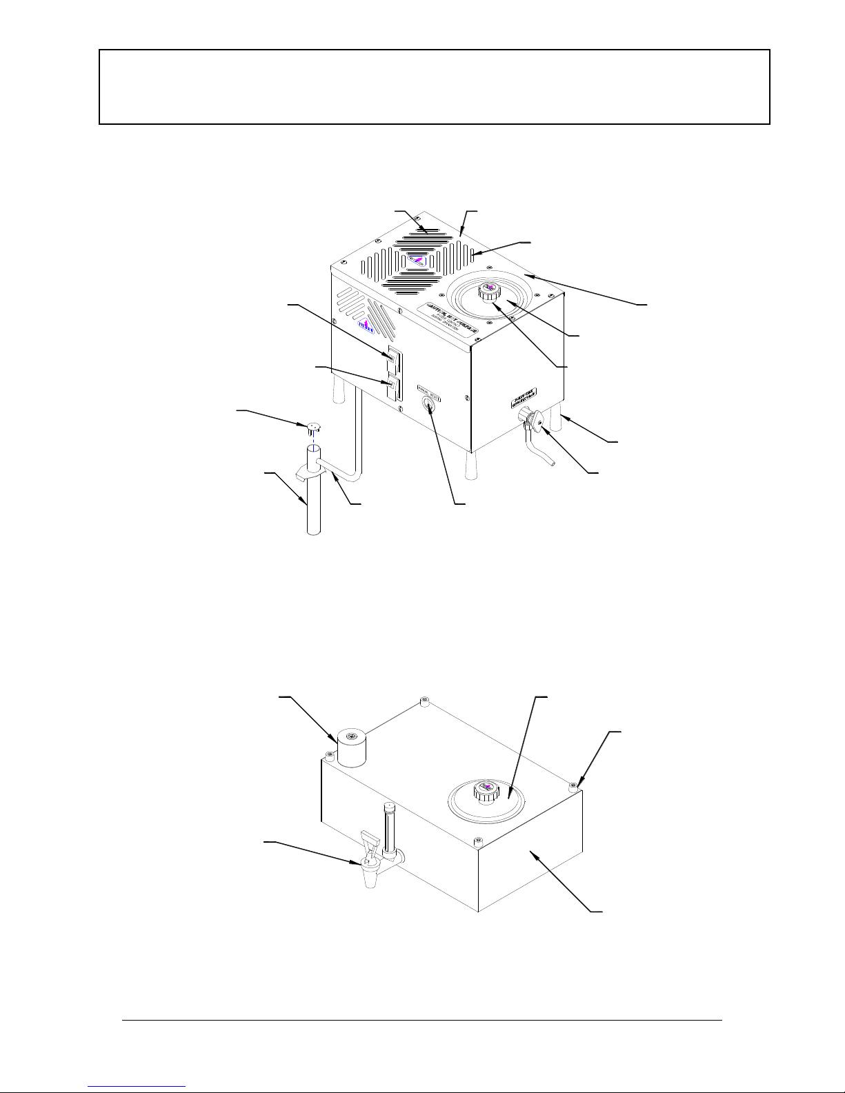
WATER DISTILLER AND OPTIONAL STORAGE TANK FEATURES ............................................9
10 FACTORS THAT WILL AFFECT YOU WATER DISTILLER PRODUCTION .........................10
UNDERSTANDING HOW PURE WATER IS PRODUCED.................................................................12
FINDING A GOOD INSTALLATION LOCATION...............................................................................13
UNPACKING YOUR WATER DISTILLER...........................................................................................13
WATER DISTILLER INSTALLATION TOOLS...................................................................................15
WATER DISTILLER LEG INSTALLATION ........................................................................................16
OPTIONAL STORAGE TANK ASSEMBLY..........................................................................................16
OPTIONAL STORAGE TANK TO DISTILLER HEAD ASSEMBLY................................................18
IMPURITIES DRAIN TUBE INSTALLATION......................................................................................19
BOILING TANK LID INSTALLATION .................................................................................................20
OPTIONAL STORAGE TANK LID REMOVAL AND INSTALLATION..........................................20
OPERATION...............................................................................................................................................21
CONTROLS -POWER,FAN,AND OVERHEAT RESET .....................................................................................21
BEFORE INITIAL WATER DISTILLER OPERATION.........................................................................................23
NORMAL OPERATION..................................................................................................................................23
MAINTENANCE AND CLEANING ........................................................................................................25
REGULAR INSPECTION AND CLEANING OF BOILING TANK..........................................................................25
CLEANING THE BOILING TANK USING CLEANER DESCALER .......................................................................26
REPLACING CHARCOAL IN POST CHARCOAL FILTER CANISTER (USED WITH 8-M).....................................27
REPLACING CHARCOAL IN CHARCOAL FILTER CANISTER (USED WITH 8-MST).........................................28
STERILIZATION............................................................................................................................................29
Liquid Sterilization of Optional Storage Tank ........................................................................................29
Steam Sterilization of Water Distiller Head............................................................................................30
Steam Sterilization of Water Distiller Head, Filter Canister and Optional Storage Tank......................32
Maintenance Schedule Table ..................................................................................................................33
Owner Maintenance Record Table..........................................................................................................33
TROUBLESHOOTING..............................................................................................................................34
ADDITIONAL OPTIONS..........................................................................................................................36
SPECIFICATIONS AND TECHNICAL INFORMATION....................................................................37
WIRING LIST AND SCHEMATICS..................................................................................................................38
INDEX..........................................................................................................................................................40
WARRANTY REGISTRATION CARD...................................................................................................41
Table of Contents

4
Introduction
Congratulations on the purchase of the most advanced water distiller
in the industry! When installed and maintained properly, your
Precision Water Systems water distiller will provide years of safe,
trouble free service. It is important to observe and follow the safety
and maintenance instructions carefully. If you have any questions or
concerns regarding installation or operation of your water distiller,
please contact your dealer.
All 120 VAC Precision Water Systems Water Distillers are certified to
cCSAus Classes 2831-02 and 2831-82 under the Canadian and
American Electrical Code.
All Water distillers are factory tested with a high voltage ‘Dielectric
Strength Test’ and ground fault test prior to shipping.
Precision Water Systems Water Distillers have been tested by
EnviroTest Laboratories which found the water distillation units to be
very effective water treatment systems capable of removing both
harmful pathogens and toxic chemicals from water. In their study all
pathogens were eliminated and none were found in the distilled
water. The water distillation system also effectively removed all of
the soluble inorganic chemicals tested. Removal efficiencies of 99%
or greater were achieved for almost every chemical tested.
All Precision Water Systems Water Distillers are operated and tested
at the factory and have produced distilled water to make sure all
components are functioning properly. All water distillers are wiped
clean before shipping, but there may be a water ring inside the boiling
tank. There may also be an off-colour line at the seams of the
storage and boiler tank. This is caused by the TIG welding process
used during manufacturing. This is normal and is not a sign of a
problem. Follow all the Before Initial Water Distiller Operation
procedures and you will have pure water in no time.
Your Precision Water Systems Water Distiller must be installed
according to any Local, State or Provincial Regulations.

5
Records
Please record all of the important information below to assist you and the service
center in case there is any service work required in the future. All of the
information is required to properly identify your water distiller and optional
storage tank and will make servicing much easier. The information is located on
the serial plate on the side of the water distiller head and optional storage tank.
The Serial Plate Location Diagram below shows sample serial plates.
Distiller Head Optional Storage Tank
Serial Plate Location Diagram
Distiller Head:
Model: PWS 8-M
Series: eg: 0001
Serial Number: eg: 0123012
Optional Storage Tank:
Model: PWS 8-MST
Series: eg: 0001
Serial Number: eg: 0123012
Date of Purchase: ___________________________________________________
SERIAL PLATE LOCATION DIAGRAM - 8GPD
SERIAL PLATE LOCATION DIAGRAM - MST

6
Precision Water Systems Water
Distiller Warranty
-The warranty for your Precision Water
Systems Water Distiller covers defects in
materials for two (2) years on all parts and
labour to the original purchaser.
-Stainless Steel parts are covered by a 15 year
pro rated warranty. This covers all stainless
steel parts such as the boiling and optional
storage tank. With this warranty it is the
responsibility of the distiller owner to properly
maintain the distiller. If there is any misuse
or abuse the warranty will be void.
-Precision Water Systems does not warrant any
transportation charges incurred to complete
the repair. The distiller owner is responsible
for all shipping charges to and from the
service center.
-Warranty is void if the distiller is found to
have been consumer damaged or misused,
caused by acts of God, unauthorized
alteration, repair or vandalism.

7
Important Safety Precautions
When using electrical appliances, basic safety precautions should always be
followed including the following:
1. Read all instructions.
2. Do not touch hot surfaces. Use handles or knobs.
3. To protect against electrical shock do not immerse cords or plugs in
water or other liquid.
4. Close supervision is necessary when any appliance is used near
children.
5. Do not allow children to operate this appliance.
6. Unplug from outlet when not is use and before cleaning. Allow to cool
before putting on or taking off parts.
7. Do not operate any appliance with a damaged cord or plug or after the
appliance malfunctions or has been damaged in any manner. Return
appliance to the nearest service facility for examination, repair or
adjustment.
8. The use of accessory attachments not recommended by the
appliance manufacturer may cause injuries.
9. Do not use outdoors.
10.Do not let cord hang over edge of table counter, or touch hot surfaces.
11.Do not place on or near a hot gas or electric burner, or in a heated
oven.
12.Extreme caution must be used when moving an appliance containing
hot water.
13.Always attach plug to appliance first, then plug cord into the wall
outlet. To disconnect, turn any controls to “off”, then remove plug
from wall outlet.
14.This appliance is intended for household use.
15.Save these instructions.
Additional Safety Recommendations
1. Always unplug appliance before servicing.
2. Do not use extension cords with appliance.
3. Ensure there is adequate air space around the appliance to allow the heat
from the appliance to be removed and supply adequate fresh air for
cooling.

8
Precision Water Systems Water Distiller
Owners’ Summary
The following is a summary of the information contained in this
Owners’ Guide and required to install and operate your Water
Distiller
1) Find a good location for installing your Water Distiller –
See Finding a Good Installation Location.
2) Unpack the water distiller and parts - See Unpacking
Your Water Distiller.
3) Assemble the Water Distiller –See
Water Distiller Leg Installation
Optional Storage Tank Assembly
Impurities Drain Tube Installation
Boiling Tank Lid Installation
4) Steam sterilize boiling tank –See Steam Sterilization
of Water Distiller Head in the Maintenance and
Cleaning section.
5) Load Charcoal Filter Canister –See Replacing
Charcoal in Post Charcoal Filter Canister (Used
with 8-M without Optional Storage Tank) in the
Maintenance and Cleaning section.
6) Follow procedure in Normal Operation section.
7) Enjoy pure, distilled water!

9
8-M Distiller Features
8-MST Optional Storage Tank Features
Water Distiller and Optional Storage Tank
Features
DISTILLER FEATURES DIAGRAM, PWS 8M
CONDENSING COIL SHIPPING STRAP
(REMOVE BEFORE USE)
FAN SWITCH
POWER SWITCH
OVERHEAT RESET SWITCH
BOILING TANK LID
GAS RELEASE VENT (HIDDEN)
CONDENSING COIL (INSIDE)
BOILING TANK
(INSIDE)
LEG
DRAIN VALVE
POST CHARCOAL
FILTER
FILTER CAP
FEED TUBE
LID KNOB
MANUAL STANDARD TANK FEATURES
SIGHT GAUGE AND
DRAIN VALVE
STORAGE TANK
CHARCOAL FILTER
CANISTER BODY
LEG
STORAGE TANK LID

10
1. Water Volume Measurement
a) How are you measuring your water? The most accurate is by weight.
1 litre of pure water = 1 kg = 1000 g = 2.2046 lbs
b) Water distillers are rated in US gallons, NOT Imperial Gallons.
1 US Gallon = 3.785 litres = 3.785 kg = 8.344 lbs = 0.833 Imp. Gallons
c) Most distilled water holding tanks do not completely drain from the tap.
Ensure this volume of water is included in your calculation by completely
draining the tank or starting your production check with this volume pre-
filled.
2. Line Voltage
The line voltage at the outlet where the distiller is connected should be checked
with a voltmeter. Line voltage is often much less than expected, especially in
rural areas. Line voltage will also usually drop off dramatically when the daily
commercial load hits the grid from approximately 8 am to 5 pm (often when the
distiller owner is not home and unable to check the line voltage). Line voltage
lower than the distiller rated voltage (on the serial plate) will drastically lower the
water production.
3. Fill Water Temperature
The water used to fill the machine may affect the water production. Cooler fill
water will take more time/energy to heat to the boiling point than hot water.
4. Ambient Air Temperature
Water distillers with cooling fans must have sufficient ventilation so that the
boiled steam can be cooled and condensed into distilled water. Restriction of air
flow (such as a closed cupboard) will result in a hot ambient air build up which
will not allow all of the steam to condense into distilled water and some water
production may escape as steam into the atmosphere through the charcoal filter
or volatile gas release vent. This steam loss can also occur in hot summer
periods or very warm climates.
10 Factors That Will Affect Your Water Distiller
Production

11
5. Heating Element and Boiler Cleanliness
As the water distiller removes impurities some of the impurities may cling to the
boiler tank and the heating element. Any of this scale may build up around the
heating element and actually insulate it, which will drastically decrease the
thermal efficiency of the heating element and require more time/energy to boil
water, which will decrease the water production.
6. Altitude
The water distiller is rated at the altitude of the manufacturer, which is
approximately 675 m (2214 ft) above sea level. Locations lower than this (closer
to sea level) will have reduced water production due to the higher boiling point of
water at higher atmospheric pressures at lower altitudes.
7. Operating Time, Warm-up Period & Suitable Storage
When checking the water distiller production, the start time should be when the
first few drops of water have entered the charcoal filter canister. Do not start
timing when the distiller turns on as it takes a few minutes for the heating
element, boiler tank and water to heat up. The distiller production rating does
NOT account for this time, but rather the continuous production after the distiller
is up to temperature. Ensure when checking production that you have suitable
water storage for holding the amount of water that will be produced.
8. Manual Fill Boiling Tank Fill Level
When checking the water distillation production on manual fill water distillers the
amount of water initially poured into the boiling tank will affect the production.
Water should be filled to the water level pin so that once the water is hot the
maximum amount of water can be distilled without having to heat up and refill.
Under-filling the boiler will decrease the amount of water distilled. Again, the
warm-up time should not be included in the production rate
9. Boiling Tank Heating Element
Once all other factors have been eliminated or checked, have an authorized
service center check that the proper heating element has been installed in your
distiller. Always replace heating elements with the manufacturers supplied
heating elements. Other elements are available from hardware stores, home
repair centers etc. and look like the same element but they are almost always not
the same. Even if the voltage and wattage are the same, they usually have
different wattage densities and most likely different element sheath materials,
which will result in premature heater burnout in continuous water distillation of
raw water. These heating elements will also likely affect you water distillation
capacity.
10. Combination of the above Factors.
Often a reduced water distiller’s production is a combination of many or all of the
above factors. To ensure maximum production from your water distiller, keep
your water distiller clean and operate it in a well-ventilated area and use room
temperature feed water where possible.

12
Your water distiller operates the same as Nature’s hydrological cycle. See
the Hydrological Cycle Diagram below. Nature uses the heat of the sun to
vaporize surface water and draw it into the atmosphere leaving the impurities
behind. As the vapour cools it condenses and returns back to the earth as rain
or snow. When rain or snow falls it passes through smog, dust and many other
types of contaminants. These contaminants can be picked up by the falling rain
or snow. Additional contamination of water can occur when it moves through the
ground.
Hydrological Cycle Diagram
Water Distillers complete their own hydrological cycle. The advantage of
a water distiller over Nature is that the water is produced in a closed environment
free of pollution and contaminants.
Your water distiller uses the boiling tank to heat the feed water to create
steam. The steam rises from the boiling tank leaving almost all of the impurities
behind. The steam enters the condensing coil and is cooled by the fan. As the
steam cools it condenses into pure distilled water and is stored in a water bottle
or optional stainless steel storage tank. The charcoal filter (between the
condensing coil and storage container) and the volatile gas vent remove any
contaminants that boil at lower temperatures than the boiling point of water. The
impurities from the process remain in the boiling tank and are drained to a
suitable drain.
CONDENSATION
EVAPORATION
SMOG, DUST, ETC.
ROCK DEEP PERCOLATION
GROUND WATER
SURFACE WATER
HYDROLOGICAL CYCLE DIAGRAM
PRECIPITATION
Understanding How Pure Water is Produced

13
Before installing your water distiller it is important to find a good location.
Following the points listed below will provide the best location for your water
distiller:
1. The water distiller must be plugged directly into a dedicated 120VAC, 15
Amp wall outlet.
2. The water distiller requires sufficient airflow around it to operate. The air
is used to cool the water distiller condensing coil. Locate the water
distiller in an area that will provide enough room for good air flow. Do not
place the water distiller in an enclosed area like a closet.
3. Locate the water distiller where a pail, suitable container or drain can be
used for the impurities drain.
4. When unpacking the water distiller and options note the sizes and
consider this when picking an installation location.
5. Locate the water distiller away from a bedroom or other area where the
noise of the water distiller may be undesirable.
6. Locate the water distiller in an area that is clean and free of dust so the
cooling coils remain clean when the fan is drawing fresh air.
Your Water distiller has been shipped in one box. The Water Distiller Box
Components Diagram shown as follows displays all of the parts that will be in
the water distiller box.
Water Distiller Box Components Diagram
Water Distiller Box Check List
Check
List
(A) 1 –Water Distiller Head
(B) 1 -- Parts Bag
(Water Distiller Parts Bag Components Diagrams shown as follows)
(B) 1x(A) 1x
UNPACKING DISTILLER BOX DIAGRAM
Unpacking Your Water Distiller
Finding a Good Installation Location

14
Water Distiller Parts Bag Components Diagram
Water Distiller Parts Bag Check List
Check
List Part No.
(A) 500409 1 –Post Filter
(B) 080115 1 –Sample Descaler/Cleaner
(C) 080116 1 –Sample Coconut Charcoal
(D) 500212 1 –Tube, Manual Drain, Stainless Steel
(E) 054009 4 –Black Plastic Legs
(F) 500184 1 –Boiling Tank Lid
(G) 052000 1 –2’ Clear Sterilization Drip Tube
(H) 018004 4 –½” x 5/16” SS Washers
1. Remove all loose pieces from the water distiller box and save all
packaging until all the parts are identified and located.
2. Check inside boiler tank and optional storage tank for any parts that may
be shipped in that area. If any parts are missing or if you have been given
the wrong part, DO NOT return the water distiller unit. Contact your dealer
for the required parts. They will be pleased to assist you.
3. Remove all protective plastic from water distiller head, boiling tank lid and
optional storage tank and lid.
(C) 1x(B) 1x
(G) 1x (H) 4x(F) 1x
(A) 1x (D) 1x
(E) 4x

15
Shipping Tie Removal Diagram
4. Refer to Shipping Tie Removal Diagram above. Cut/Remove the coil
support tie located on the top of the water distiller head. Be careful not to
scratch the water distiller when removing. This tie supports the cooling
coil during shipping only.
TOOLS REQUIRED:
For Water Distiller Installation
(A) 5/8” Open End Wrench
(B) Adjustable Wrench
Water Distiller Installation Tools
TOOL REQUIRED FOR DISTILLER INSTALLATION, EAU M
(A) (B)
OR
COIL SUPPORT TIE
WATER DISTILLER HEAD
SHIPPING TIE REMOVAL DIAGRAM

16
1. Refer to the Water Distiller Leg Installation Diagram shown
below. Place a ½ x 5/16” stainless steel washer on the threads of
each leg and screw the legs into the bottom of the distiller head.
Water Distiller Leg Installation Diagram
Sight Tube Assembly
1. Remove the sight gauge from the parts bag and packaging.
Sight Gauge Installation Diagram
Water Distiller Leg Installation
Optional Storage Tank Assembly
DISTILLER LEGS INSTALL DIAGRAM
BULKHEAD
WASHER
LEG
POWER CORD
SIGHT GAUGE INSTALL DIAGRAM
3/8" JAM NUTSTORAGE TANK
SIGHT GAUGE
VALVE HANDLE
DRAIN VALVE THREADED FAUCET END
GASKET

17
2. Refer to the Sight Gauge Installation Diagram above. Remove
the plastic hex jam nut from the threaded body of the valve (leaving
water gasket on threads).
3. Remove the storage tank lid by holding down on the lid and turning
the black knob counter clockwise approximately five turns. Slide
the lid to one side and turn the knob and lid while tilting. This
should allow the Tee Bar bracket under the lid to come out of the
tank opening. Slide the lid out.
4. Push the gasket tightly up against the valve.
5. Insert the threaded valve end with gasket attached through the hole
on the front of the storage tank.
6. While holding the sight gauge with valve in the storage tank hole
with one hand, insert your other hand with the plastic hex jam nut
through the storage tank lid opening.
7. Place the hex nut onto the threaded end of the valve.
8. Hand tighten the hex nut clockwise onto the valve.
Tightening Sight Gauge Nut Diagram
9. Refer to the Tightening Sight Gauge Nut Diagram above. To
fully tighten the nut, turn the valve counter-clockwise1/4 of a turn to
the start position and ensure that the jam nut is still hand tight.
Holding the jam nut, turn the valve clockwise until upright at the
finish position.
10.Make sure the storage tank is free from any dust or material and
replace the storage tank lid.
11.Check for leaks when storage tank begins filling.
NOTE: The sight glass is fragile, do not push on the gauge (push on
bottom near threaded area).
SIGHT GAUGE INSTALLATION DIAGRAM

18
1. If you have purchased the optional storage tank, place the Charcoal
Canister in the top of Storage Tank.
2. Place lid on storage tank.
3. Refer to the Distiller Head to Optional Storage Tank Assembly
Diagram below. Place Distiller head on top of the optional storage tank
by placing the legs of the distiller head onto the leg stubs on the optional
storage tank.
Distiller Head to Optional Storage Tank Assembly Diagram
Optional Storage Tank to Distiller Head
Assembly
CHARCOAL FILTER
CANISTER BODY
DRAIN VALVE
VALVE HANDLE
THREADED FAUCET END
STORAGE TANK TO DISTILLER HEAD ASSEMBLY DIAGRAM
STORAGE TANK
SIGHT GAUGE GASKET
LEG
STORAGE
TANK LID
DISTILLER HEAD
3/8"
JAM NUT

19
1. Refer to the Impurities Drain Tube Installation Diagram shown below.
Remove the compression nut and compression sleeve from the Drain
Valve.
Impurities Drain Tube Installation Diagram
2. Take the stainless steel manual drain tube from the parts bag. Slip the
compression nut and compression sleeve over the manual drain tube.
3. While holding the compression nut and sleeve on the drain tube, push the
manual drain tube into the drain valve. Push the compression sleeve into
the valve with the nut and thread the nut onto the valve.
4. Position the drain tube away from the distiller and tighten the nut with a
5/8” open end wrench or adjustable wrench. When draining the boiling
tank of the water distiller, the manual drain tube should be drained into a
suitable container or sewer.
Impurities Drain Tube Installation
DISTILLER HEAD
MANUAL DRAIN VALVE INSTALL DIAGRAM
COMPRESSION SLEEVE
COMPRESSION NUT
MANUAL DRAIN TUBE
DRAIN VALVE
TO SEWER OR
IN A CONTAINER

20
1. Remove any protective plastic coating (white, blue or clear plastic) from
the lid.
Boiling Tank Lid Operation Diagram
2. Refer to the Boiling Tank Lid Operation Diagram above. Take the
boiling tank lid in your hand. Hold the Tee Bar bracket and turn the Lid
Knob counter-clockwise so that there is ½” of space between the Tee Bar
bracket and the lid.
3. Tip the lid so that the Tee Bar bracket slips under the rim of the boiling
tank opening on one side, and then slide the lid so the Tee Bar bracket
slips under the other side of the rim. Center the lid.
4. Turn clockwise to tighten the lid onto the boiling tank. The water level pin
inside the boiling tank will prevent the lid from turning while tightening.
Practise removing and replacing the lid a few times as the lid will need to
be removed each time the water distiller is filled or cleaned.
1. To remove the optional storage tank lid, turn the Lid Knob counter-
clockwise while lifting. Lifting while turning holds the Tee Bar bracket
under the lid and allows you to loosen the lid. Continue turning and lifting
until there is ½” of space between the Tee Bar bracket and the lid.
2. Tip the lid so that the Tee Bar bracket slips out from under the rim of the
optional storage tank opening on one side, and then slide the lid so the
Tee Bar bracket slips out from under the other side of the rim.
3. To Replace the optional storage tank lid, tip the lid so that the Tee Bar
bracket slips under the rim of the boiling tank opening on one side, and
then slide the lid so the Tee Bar bracket slips under the other side of the
rim. Center the lid.
4. While lifting up on the optional storage tank lid knob, turn clockwise to
tighten the lid onto the optional storage tank. When upward pressure is
no longer needed to prevent the lid from turning the lid is tight.
Boiling Tank Lid Installation
Optional Storage Tank Lid Removal and
Installation
BOILER LID INSTALL DIAGRAM
This manual suits for next models
3
Table of contents