Precision NPFC Series User manual

1
Lithium Iron Phosphate Battery
NPFC SERIES
(LiFePO4 Battery Module for Telecom)
Operation Manual

12
Contents
Notes | Safety and Warning
One | Product Information
Product Features
Main Application
Dimensions
Layout
Working Principle
Two | Technical Characteristic
Electric Performance
Discharge Performance
Charge Performance
Three | Operation
Perameter Settings
Operation Condition
Four | Storage and Installation
Storage
Installation
Five | Maintenance
General
Troubleshooting and Solutions
Annex1
Annex2
Annex3
Annex4
03
04
4
4
5
6
8
10
10
11
11
12
12
12
13
13
13
18
18
19
20
21
22
23

3 4
Safety and Warning
Chapter Notes
The NPFC series LiFePO4battery system installation, operation,
maintenance should follow important recommendations in this manual:
• The equipment shall be installed by the professional trained staff.
• Battery maintenance should be carried out by the experienced professionals and aware of the preventive measures
on the potential harm of the battery.
• Note: Be care of the risk of electric shock for large current in case of battery short circuit, pay attention to the
following points during operation
-Remove watches, rings or other metal objects
-Use tools with insulated handles
-Do not place tools or metal objects on the battery
• Do not direct access to the battery system to the mains grid power outlet.
• Do not put the battery system into re, do not use or storage the battery near to the high temperature source.
• Do not use liquid or other objects placed into the battery system.
• Do not open or cut the battery, not hit, throw or step on the battery.
• Using special communication between battery module and power plant to charge battery
• Be sure to subject to charge and discharge parameters setting in this manual.
• The output interface of the system is still voltage when grid power cut, avoid electric shock or short circuit when
operation.
• Please check if the box is damaged. If damaged, please immediately notify the supplier
• If you nd leaking liquid or white powder residue on product, prohibit operation.
Product Introduction
Chapter One
Product Features
NPFC series battery system is 48V system for communications back-
up type LiFePO4 (lithium iron phosphate) battery products, the system
uses the advanced LiFePO4 battery technology with the benefit of long
cycle life, small size, light weight, safety and environmental protection,
and has a strong environmental adaptability, it is idea for harsh outdoor
environments.
The system also integrates a smart battery management and monitoring
module, support for remote centralized monitoring and remote battery
management and maintenance, to meet the requirements
of unattended. Therefore, the NPFC system can fully meet the backup
power supply requirements of the access network equipment, mobile
communications equipment, transmission equipment, micro base stations
and microwave communication equipment.
Main Application
• Network Telecommunication Facilities
• OSP
• Terminal of FTTX
• Access network system
• Indoor distribution system
• Telecom BTS
• Integrated outdoor power cabinet
• UPS
• Internet data center (IDC)
• Solar energy
• Common Bonding Network (CBN) and or Isolated Bonding Network (IBN)
Warning
Read the
manual
Fire
forbidden
Circle used The product has
passed the UL
authentication
Do not put
batteries into
dustbin
Please take care of the following marks
Electricity
danger
Protecting
your eyes
With adults
custody
Watch
Short-circuits

5 6
Dimension
Fig.1-1 Structural Drawing of NPFC Series Batteries (48NPFC100 as example)
Fig.1-2 Battery Output Terminal
Table 1-1 Battery Model & Dimension of NPFC Series
Note:
1. Battery Model: Battery models listed in the datasheet are standard products. Narada can also supply customized design
in cell, BMS and dimensions for various application scenarios.
2. Terminal Torque: M4, 2~3 N•m ; M6, 7~8 N·m ; M8, 9~10 N·m;
Layout
Fig. 1-3 Layout of Front Panel for NPFC Series Batteries
(Received product may not have all parts above, this instruction is as an example)
Table 1-1 Battery Model & Dimension of NPFC Series
48NPFC10
48NPFC20
48NPFC50
48NPFC80 (3U)
48NPFC100 (5U 19”)
48NPFC100 (3U 23”)
48NPFC100 (3U 19”)
1
2
3
4
SOC
ALM
RUN
ADD Dip
switch
Indicators
for capacity
Indicators
for alarms
Indicator for
runing status
Address for
communication
Battery Model
Dimensions (mm)
Width
(No Ear)
6.4
11.5
28.5
37.5
44
48.0
38.5
442
442
442.5
442.5
442.5
522.5
442.5
44
88
132.5
132.5
222
132.5
133
243
243
390
400
400
420
400
M4
M4
M6
M6
M6
M6
M8
Typical
Weight
(kg)
Height Depth Φ
Battery
Output
Terminal
SOC is short for state of charge. There are four green
LED lights in front panel indicating SOC. Each SOC
LED light represents 25% of rated capacity. Detailed
information is shown in Annexed Table 1.1.
There is one red LED light in front panel indicating
alarms. Detailed information is shown in Annexed Table
1.3.
There is one green LED light in front panel indicating
running status. Detailed information is shown in
Annexed Table 1.2.
ADD is applicable to modules connected in parallel. ADD
consists of six binary bits. Detailed information is shown
in Annex 2.
No. Marks Functions Detailed Information
7 8
5
6
7
8
9
10
11
12
13
RS232
RS485
RESET
Dry
contact
Power
switch
Battery
Output
GND
Openable
Panel
(optional)
Side
mounting
communication
port
communication
port
Reset button
Dry contact
ON/OFF switch
Terminals for
battery output
Ground screw
Openable
Panel
Wall-hanging
installation
RS232 communication port just for software upgrade
now.
It is adopting RS485 series port communication pattern
to upload data. Contents of data transmit include
BMS parameters, battery running status, alarms, etc.
Communication of modules connected in parallel is
available through RS485.
Press RESET button when abnormity occurs to assure
stability of battery performance.
Failure Alarm: indicate BMS or battery fail including but
not limited to charge and discharge MOS fail, cell
voltage under 0.5V, NTC disconnect, and so on.
When turn-off, battery get into sleep mode, and cut-off
output, the alarm output also will be stopped.
Using terminals with four or two cores. Polarities are
+, -,+, - from left to right. The two ‘+’ and ‘-’ are equal
relatively. Detailed information is shown in Fig. 1-2.
Connect earth by flexible cable above GREEN
Sheathed, UL94-V0, gauge of the grounding wire should
be equal to or greater than the gauge of the battery
return wire.
Battery BMS can be removable and replace easily
through this.
The side mounting is used to wall-handing installation
battery. Also use the ear to handle the battery.
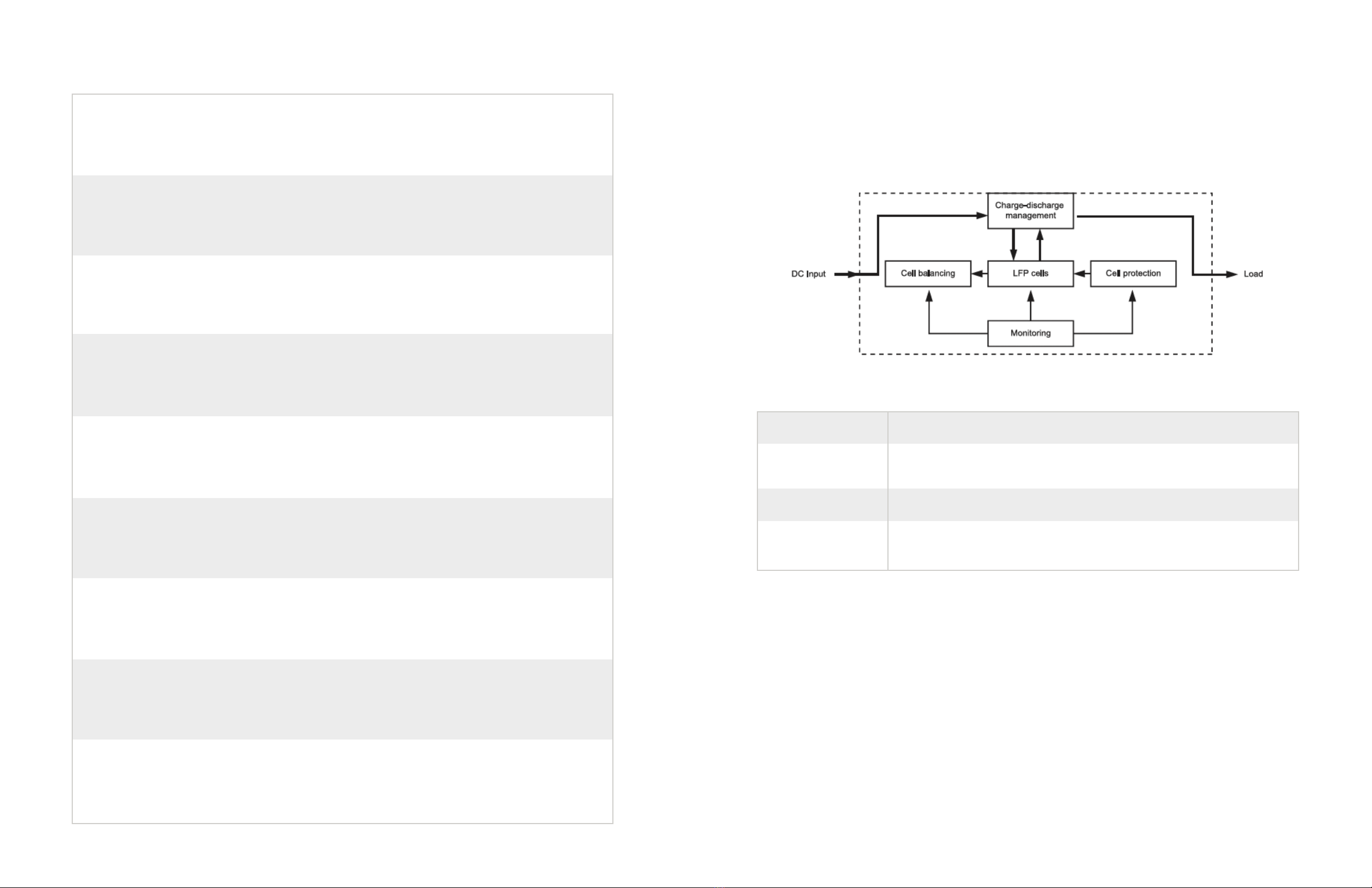
Working Principle
The NPFC battery system mainly includes Lithium battery pack, battery
protection, cell balancing unit, monitoring module and charge-discharge
management module for optional. Its schematic diagram shown in Figure 1-4
Fig.1-4 Schematic Diagram
NPFC battery working principle:
DC power input rectifier after filter, DC divided two circuits, one circuit
directly supply the load, another circuit charge lithium battery. When
grid power on, the system supplies the loads and charging inside lithium
batteries; When grid power failure, lithium inside system supply DC power
to the load, to ensure uninterrupted power supply as power system.
Battery Management System (BMS)
Smart BMS technology is adopted for battery modules of NPFC series to
assure smart automaticmanagement for batteries. Features of BMS are
shown as below:
LFP cells
Cell Protection
Cell balancing
Monitoring
Chemical power, energy storage and power supply components
Protect LFP cells against overcharge, over discharge, over current, over
temperature, short circuit
Equalization LFP cells for cells unbalanced
Suport centralized monitoring system (optional according to customer
requirements)
Table 1-1 Battery Model & Dimension of NPFC Series Continued

9 10
• There is a centralized monitoring unit in BMS. Functions such as remote measurement, remote
communication, remote controlling are available. Battery modules can be controlled remotely
by staffs in control center. NPFC series are in line with the requirements of the development of
modern communications technology.
• It is combined by technologies of power source and computer. Parameters and status of
rectifiers and AC/DC distributions can be detected and controlled.
• Excellent electromagnetic compatibility. BMS used for battery modules of NPFC series can
comply with the outdoor power plants during operation, no interfere with each other.
• BMS can provide protections against overcharge, over-discharge, over-temperature, over
current, short circuit, etc., to assure reliable safety and operation life.
• With patented cell balancing technology, BMS provide high efficiency for cell balancing and
prolong system operate life.
• Configuration flexibility, support parallel connection expansion
Technical Characteristic
Chapter Two
Note:
1 Battery Model Battery models listed in the datasheet are standard products.
2 Rated Voltage 48V = 3.20Vpc * 15pcs (Rated voltage of each LFP cell is 3.20Vpc)
3 Rated Capacity Five-hour rate capacity (0.2C to 40.5V at 25° C)
Electric Performance
48NPFC10
48NPFC20
48NPFC50
48NPFC80
48NPFC100-19”
48NPFC100-23”
Battery
Model
48
48
48
48
48
48
10
20
50
80
100
100
2
4
10
15
20
20
10
20
50
80
100
100
10
20
50
80
100
100
54.0
54.0
54.0
54.0
54.0
54.0
40.5 to 54.5
40.5 to 54.5
40.5 to 54.5
40.5 to 54.5
40.5 to 54.5
40.5 to 54.5
Rated
Voltage
(V)
Rated
Capacity
(Ah)
Voltage
Rage
(V)
Charge
Voltage
(V)
Charge Current (A)
Recomm Max.
Max.
Discharge
Current (A)
123
11 12
Operation
Chapter Three
Parameter Settings
Lead-acid batteries can be replaced by lithium battery of NPFC series if
power is matched. Table 3-1 is new parameter settings of power plant for
lithium battery.
Table 1-1 Battery Model & Dimension of NPFC Series
Note:
1.Equalization charge is requested to switch off for NPFC series batteries.
2.Rectifier parameter shall be set according to specific site requirement based on battery units used.
3.If the battery connected more than 2 in parallel, the max. charge current recommend 0.5C.
Operation Condition
Table 3-2 Requirements for Operation Environment
No.
1
2
3
4
5
6
7
8
9
10
11
12
13
Parameters
Float charge coltage
Equalization charge voltage
Standard charge current
Charge current limitation
Equalization charge interval
Equalization charge duration
Condition to equalization charge
Condition to float charge
Recovered LLVD voltage
LLVD
BLVD
Temperature compensation for float charge
Temperature compensation for equalization charge
Units
V
V
A
A
day
H
A
A
V
V
V
-mV/°C
-mV/°C
Defaults
54.0
NA or 54.1
0.2C
0.5C ~ 1.0C
NA
NA
NA
0.05C
50.0
47.0
43.2
NA
NA
Temperature Range (°C)
Recommended
Temperature(°C)
Humidity
Discharge
Charge
Storage
-25 ~ +75
-10 ~ +65
0 ~ +40
+15 ~ + 35
+15 ~ + 35
+15 ~ + 30
5% ~ 95%
Discharge
Charge
Storage
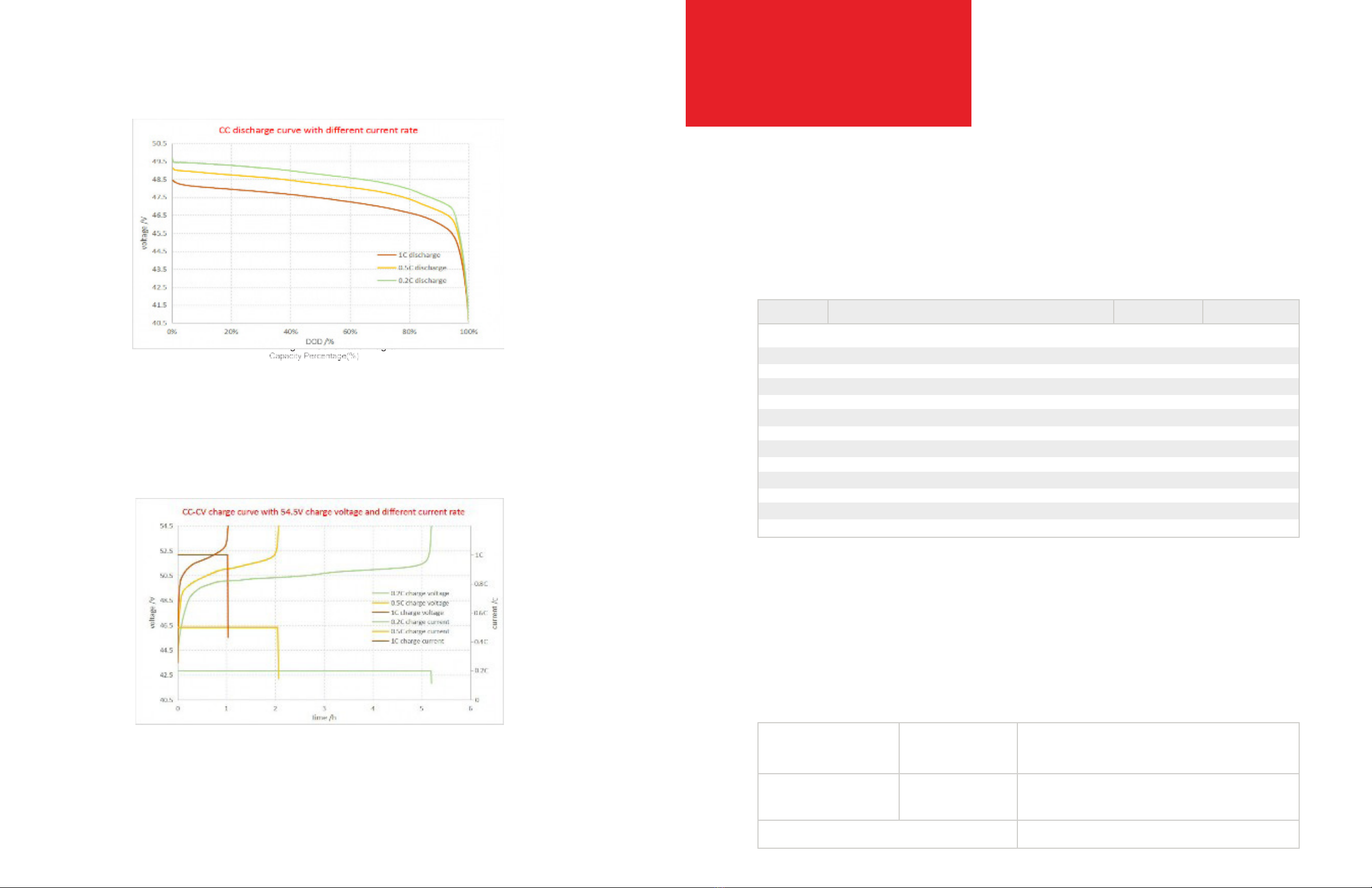
Discharge Performance
Fig.1-4 Schematic Diagram
Charge Performance
Fig.1-4 Schematic Diagram

13 14
Storage and Installation
Chapter Four
Storage
• Storage temperature range: 0°C to 40°C.
• Storage battery should be at 50%-80%SOC.
• Recharge charge before using to recover capacity loss of self-discharge during storage and transport.
• Recharge battery during long-term storage for self-discharge. Recharge program as follow table:
• Storage battery over 40°C or under 0°C will reduce battery life,
• Storage battery in dry and low temperature, well ventilated place
• Battery performance degradation after long-term storage, please shorten shelf time as possible as you can.
Installation
Unboxing & Inspection
• Please study this manual before installation.
• Please inspect the package before unboxing, if any destroy with appearance, contact with the supplier as soon as
possible.
• This device shall be installed and operated by professionals.
Preparation for Installation
• Batteries shall not be placed in direct sunshine or close to heat source.
• Batteries shall be installed in place with good ventilation to assure enough heat dissipation.
• Batteries shall be placed in are with clean ambient and low humidity.
• Heavy weight shall not be placed on any cable.
• Following are the tools possibly but not limited be use for installation:
Storage Temperature
0°C-30°C
30°C-40°C
Recharge interval
Every 6 months
Every 3 months
Single Module Recharge Procedure
1) Charge with 0.2C to 100%SOC
2) Discharge with 0.2C to 0%SOC
3) Charge with 0.2C per module for 4 hours
Tool items (possibly but not limited)
Installation of Battery Modules
1. Installation and fixation
Battery modules of NPFC series are applicable to installation in cabinets
and wall-hanging.
• Cabinet installation
Insert battery module into cabinet, and fix two handles of battery module with cabinet rack
using 4pcs M6 screws.
• Wall-hanging installation
Wall-hanging installation also can be adopted, fix two handles of battery module with triangle
rack on the wall using 4pcs M6 screws.
Preferred
Forbidden (Except for 48NPFC10, 48NPFC20, 48NPFC100-19)
Alternate

15 16
2. Ground connection
Connect earth by flexible cable above GREEN Sheathed, UL94-V0, gauge
of the grounding wire should be equal to or greater than the gauge of the
battery return wire, .no less than 6AWG, connection through 2-hole 0.75in
center spacing, on right side of cabinet back.
3. Battery output connection
• Connect ‘+’ of battery output with positive copper bar of power plant, and ‘-’ with negative
copper bar or power switch.
• If multi battery modules will be connected in parallel, please take note of follows:
• Color for cable between ‘+’ and positive bar is suggested as RED, and cable between ‘-’ and
negative as BLACK.
• The picture of paralleling connection for NPFC Series Batteries see Fig. 4-2. There is a tray
under each battery to support the battery.
Fig. 4-1 Ground connection for NPFC Series Batteries
1. The battery modules connected no more than 8 in parallel.
2. The minimum spacing between batteries is 10mm.
3. Connect ‘+’ of battery output of each battery module with positive copper bar of power
plant, and ‘-’ with negative copper bar of power plant or power switch separately.
4. Length of cable between battery module and power plant shall be less than 2.0m. To
make sure similar voltage drop of cable for each battery, length of all positive and
negative cables should be the same.
4. Power on for battery module
• When installation is accomplished, battery module is in dormant state. Once power on for
the power plant and battery module, battery will go into normal running status, and discharge
charge can be available.
• Parameter settings for lithium battery modules in power plant are shown in Table 3-1.
5. RS232/RS485 communication connection
• If there is only one battery module in operation, communication between battery module and
computer can available through RS485.
• If there are more than one battery modules in operation, parallel communication can be
available using RS485.
• The last battery in each rack has an empty RS485 port, its need to be connected with a cable
with RJ45 terminals to avoid interference with communication. The other end of the cable
should covered with insulating tape Its also can insert a 120Ω terminators.
• RS232 communication port just for software upgrade.
• Communication protocols for RS485 are shown in Annex 3.
• Dry contact should be connected when battery connected in electric circuit.
Fig. 4-2 Layout of paralleling connection for NPFC Series Batteries

17 18
6. Discharge with dummy load
• Dummy load cannot be larger maximum discharge current of each battery model according to
the datasheet, and BLVD is larger than 43.2V.
• Voltage drop on cable between battery module and power plant shall be less than 0.5V. Method
of calculation for cross sectional area of cable is shown as below.
A=ΣI×L/(K×∆U)
In the above formula, A is across sectional area of wire (mm2), ΣI is the total current (A), L is
length of cable, ∆U is the permit voltage drop on cable (V), and K is electrical conductivity of
wire. For example, for copper, K = 57.
Fig. 4-3 How to handle the empty RS485 port for NPFC Series Batteries
Maintenance
Chapter Five
General
Proper maintenance will prolong the life of a battery and will aid in
assuring that it can satisfy its design requirements. A good battery
maintenance program will serve as a valuable aid in determining the
need for battery replacement. The users must consider their application
and reliability needs if maintenance procedures, other than those
recommended in this document, are used. Battery maintenance should
be performed by personnel knowledgeable of batteries and the safety
precautions involved.
NPFC series lithium batteries can be used at an altitude of less than 5000
meters. If the altitude more than 5000 meters, it will affect the battery
performance and life due to the decrease of air pressure and temperature.
• The battery shall be recharged every three months if in long time storage
• Please clean the dust by the dust collector when dust is accumulated on vent
• Please use clean and dry cloth/fabric to clean up the cabinet, if need further cleaning, please
use neutral cleanser. Alcohol or ammonia synthesis is forbidden.
• Carrying shall be handled gently, prevent from severe compact
• Prevent battery from splashing liquid
• Suggest inspect the tighten of output screw every two years

19 20
Troubleshooting and Solutions
Table 5-1 Troubleshooting and Solutions
Different flash status of LED indicators represents corresponding running
status or alarms. Detailed information is shown Annex 1.
Note: The improvement of product and technology, and the possible of battery specification and
appearance changes, Narada hold the right of final explanation!
Troubles
Battery cannot
discharge
Battery cannot
charge
All LED indicators on
Communication
failure
Troubleshooting
Protection against under-voltage
Protection against over-
temperature or undertemperature
(cell temperature is lower than
-20°C or higher than 70°C)
Battery output is short circuit
Protection against over current
System failure
Battery is fully charged. Normal
chargemanagement
Protection against over voltage
Protection against over-
temperature or undertemperature
(cell temperature is lower than
-10°C or higher than 70°C)
System failure
System failure
Fault of communication cable
Halt of System communication
management
System failure
Single Module Recharge Procedure
Charge battery
Regulate cell temperature in the range of -20°C
to 70°C for discharge
Relieve short circuit and charge battery
Remove some unimportant load and charge battery
Shutdown system and call maintenance service
Do not need to solve
Do not need to solve
Regulate cell temperature in the range of 0°C to
55°C for charge
Shutdown system and call maintenance service
Shutdown system and call maintenance service
Inspect communication cable
Press RESET button
Shutdown system
Call for maintenance service
Annex 1-Instructions for LED Flash
Annex Table 1.1 – SOC LED Indicators Description
Note: mean light on, mean light off
Annex Table 1.2 – RUN Indicators Description
Annex Table 1.3 – ALM Indicators Description
Annex Table 1.4 – Flash Instruction of LED Indicators
SOC
75% ~ 100%
50% ~ 75%
25% ~ 50%
0% ~ 25%
Running Status of Battery
Activation state, but neither charge nor discharge
Charging state
Discharging state
Dormant state
Alarm Information of Battery
Minor Alarm(Various Alarm Status)
Fail(Various fail)
Major Alarm(Various protection status)
Normal, no alarm
Flash Status
Flash 1
Flash 2
Continue light
Extinguish
Flash Status
Extinguish
Flash 2
Flash 3
Extinguish
Flash Status
Flash 1
Flash 2
Flash 3
ON
0.25s
0.5s
0.5s
OFF
3.75s
0.5s
1.5s

21 22
Annex 2 – Instructions for ADD Dip Switch
ADD Dip Switch is applicable to modules connected in parallel. ADD
consists of four binary bits
Annexed Table 2.1 – Instruction for Addresses of Communication
Annexed Table 2.2 – Instruction of ADD for Parallel Communication
Note: Counting of ADD must begin from 0001, without interruption, or parallel communication cannot
be available
Instructions for ADD Dialing
1
OFF
ON
OFF
ON
OFF
ON
OFF
ON
OFF
Module No.
Default ADD
PACK 1
PACK 2
PACK 3
PACK 4
PACK 5
PACK 6
PACK 7
PACK 8
Binary Code
0000
0001
0010
0011
0100
0101
0110
0111
1000
2
OFF
OFF
ON
ON
ON
OFF
ON
ON
OFF
3
OFF
OFF
OFF
OFF
OFF
ON
ON
ON
OFF
4
OFF
OFF
OFF
OFF
OFF
OFF
OFF
OFF
ON
Default
0000
PACK 1
0001
PACK 5
0101
PACK 2
0010
PACK 6
0110
PACK 3
0011
PACK 7
0111
PACK 4
0100
PACK 8
1000
Annex 3 – Communication Protocol for
RS232 and RS485
There is one RS232 port in front panel for software upgrade, and one
RS485 port in front panel for communication between battery and PC, also
for communication between battery modules connected in parallel.
Annex Table 3.1 – RJ11 Pins Assignment (RS232)
Annex Table 3.2 – RJ45 Pins Assignment (RS485)
Sketch
Sketch
RJ45 Pins
1
2
3
4,5,6,7,8
RJ11 Pins
1
2
3
4
Definition
GND
RS485_A
RS485_B
No connection
Definition
GND
Pack receipt, computer delivery
Pack delivery, computer receipt
No connection
2 RXD Receive data - From battery to computer
3 TXD Deliver data - From computer to battery
5 GND – Signal ground

23
Annex 4 – Operation of Openable Panel
The front panel of the battery can be opened and closed to facilitate BMS
maintenance. When opening the front panel, the two bolts at the bottom of
the battery need to be removed first, then turn the three bolts on the front
panel to open it.
Fig. 5 Positions of the bolts that to open the front panel
This manual suits for next models
5
Table of contents
Popular Camera Accessories manuals by other brands

Sea & Sea
Sea & Sea 50145 instruction manual

Blackmagicdesign
Blackmagicdesign Design 3G-SDI Arduino Shield Installation and operation manual

Sea & Sea
Sea & Sea DX-3000G instruction manual

Foxtech
Foxtech FH230 TIR manual

OutBack Power
OutBack Power EnergyCell TT Series quick start guide

pro master
pro master GH26 manual


