Preen ADG-L Series User manual

ADG-L Series (5kW/10kW/15kW)
Programmable DC Power Supply
User Manual
AC Power Corp. (Preen)
V 1.04.00 EN
The information in the document is subject to change without notice.
Copyright 2022 AC Power Corp. (Preen). All roghts reserved.

Legal Notices
The information in this product manual is subject to change without notice.
AC Power Corp. makes no warranty of any kind with regard to this user ma
nual, including, but not limited to, the implied warranties of merchantability
and fitness for a particular purpose. AC Power Corp. shall not be held liable
for errors contained herein or direct, indirect, special, incidental or consequen
tial damages in connection with the furnishing, performance, or use of this
material.
Copyright Notices. Copyright 2022 AC Power Corp. (Preen), all rights reserved.
Reproduction, adaptation, or translation of this document without prior writt
en permission is prohibited, except as allowed un-der the copyright laws.

Warranty
Preen’s ADG-L series is warranted against defects in material and workmanship for a
period of one (1) year after date of shipment. Preen agrees to repair or replace any
assembly or component found to be defective, under normal use during this period.
Preen’s obligation under this warranty is limited solely to repairing any such product
which in sole Preen’s opinion proves to be defective within the scope of the warran-
ty when returned to the factory or to an authorized service center. Transportation to
the factory or service center is to be prepaid by the purchaser. Shipment should not
be made without prior authorization by Preen.
This warranty does not apply to any products repaired or altered by persons not
au-thorized by Preen, or not in accordance with instructions furnished by Preen. If
the product is defective as a result of misuse, improper repair, or abnormal condi-
tions or operations, repairs will be billed at cost.
Preen assumes no responsibility for its product being used in a hazardous or
dan-gerous manner either alone or in conjunction with other equipment. High volt-
age used in some products may be dangerous if misused. Special disclaimers apply to
these products. Preen assumes no liability for secondary charges or consequential
damages and in any event, Preen’s liability for breach of warranty under any con-
tract or otherwise, shall not exceed the purchase price of the specific product
shipped and against which a claim is made.
Any recommendations made by Preen for use of its products are based upon tests
believed to be reliable, but Preen makes no warranty of the results to be obtained.
This warranty is in lieu of all other warranties, expressed or implied, and no
repre-sentative or person is authorized to represent or assume for Preen any liability
in connection with the sale of our products other than set forth herein.
AC Power Corp. (Preen)
USA
192 Technology Dr., Suite S, Irvine, CA 92618
TEL +1 949-988-7799
Taipei
3F No. 200 Gangqian Road, Neihu Dist., Taipei 114, Taiwan
TEL +886 2-2627-1899 FAX +886 2-2627-1879
www.preenpower.com

SAFE SUMMARY
The following general safety precautions must be observed during all phases of
op-eration, service, and repair of this equipment. Failure to comply with these
precau-tions or specific WARNINGS given elsewhere in this manual will violate safety
stand-ards of design, manufacture, and intended use of the equipment.
Preen assumes no liability for the customer‘s failure to comply with these re-
quire-ments.
1) BEFORE APPLYING POWER
Verify that the equipment is set to match with the power line input.
2) PROTECTIVE GROUND
Make sure to connect the equipment to the protective ground to prevent an
electric shock before turning on the power.
3) NECESSITY OF PROTECTIVE GROUNDING
Never cut off the internal or external protective grounding wire, or disconnect
the wiring of protective grounding terminal. Doing so will cause a potential shock
hazard that may bring injury to a person.
4) DO NOT OPERATE IN AN EXPLOSIVE ATMOSPHERE
Do not operate the equipment in the presence of flammable gases or fumes.

5) DO NOT REMOVE THE COVER OF THE EQUIPMENT
Hazardous voltages may be present when the covers are removed. Component
replacement and internal adjustment can be done only by qualified service per-
sonnel.
Warning
LETHAL VOLTAGES
。
The equipment can supply 1000V peak at its output. DEATH
on contact may result if either the output terminals or the circuits connected to
the output are touched when the power is applied.

ADG-L Series Programmable DC Power Supply
Table of Contents
1GENERAL INFORMATION 1
1.1 INTRODUCTION 1
1.1.1 V/I OUTPUT LIMIT 2
1.2 KEY FEATURES 2
1.3 SPECIFICATIONS 3
1.4 EXTERIOR 10
1.5 NAME OF PARTS 12
2INSTALLATION 15
2.1 CHECKING THE PACKAGE 15
2.2 PREPARATION 15
2.2.1 NOTICE FOR INSTALLATION 15
2.3 INPUT INFORAMATION 17
2.3.1 RATED VALUE 17
2.3.2 WIRE SELECTION 18
2.4 INPUT CONNECTION 22
2.5 OUTPUT CONNECTION 23
2.6 REMOTE SENSE CONNECTION 24
2.7 FUNCTION DIP SWITCH 27
2.8 ANALOG CONNECTION 28
2.9 RS-232/RS-485 INTERFACE CONNECTION 31
2.9.1 REMOTE CONTROL CONNECTION 32
2.9.2 REMOTE CONTROL SETUP 32
2.10 OPTIONAL:EXTERNAL COMMUNICATION BOARD (MODBUS&SCPI) 34
2.11 ACCESSORY POWER OUTLET 35
2.12 USB INTERFACE (FOR FIRMWARE UPDATE ONLY) 35
2.13 POWER-ON PROCEDURE 36
2.14 HANDLES INSTALLATION 37
2.15 OPTIONAL COMMUNICATION INTERFACE CARD INSTALLATION 38
3LOCAL OPERATION 39

ADG-L Series Programmable DC Power Supply
3.1 INTRODUCTION 39
3.2 TOUCH SCREEN AND ROTARY KNOB OPERATION 39
3.3 MAIN PAGE 41
3.3.1 CONSTANT VOLTAGE (CV) MODE SETTING 43
3.3.2 CONSTANT CURRENT (CC) MODE SETTING 43
3.3.3 CONSTANT POWER (CP) MODE SETTING 44
3.4 MENU PAGE 45
3.5 SETTINGS PAGE 46
3.5.2 PROTECTION PAGE 55
3.5.3 DIAGNOSIS PAGE 61
3.5.4 ADVANCED PAGE 62
3.6 COMMUNICATION PAGE 67
3.6.1 CONTROL MODE PAGE 67
3.6.2 GPIB INTERFACE BOARD (OPTION) 68
3.6.3 ETHERNET/RS-485/RS-232/USB INTERFACE BOARD (OPTION) 68
3.7 WAVE PAGE 70
3.8 EVENT PAGE 72
3.9 INFORMATION PAGE 73
3.10 PROGRAMMABLE (PGM.) FUNCTION 75
3.10.1 PGM. PAGE 75
3.10.2 MEMORY GROUP SETTING 77
3.10.3 STEP LOOP 77
3.10.4 EXAMPLE OF STEPS FOR SIMULATAION 79
3.11 MULTIPLE MACHINE (MULTI MACH) FUNCTION 80
3.11.1 MULTI MACH SETTING 80
3.11.2 MULTI MACH INFORMATION 83
4REMOTE OPERATION 84
4.1 INTRODUCTION 84
4.2 CONTROL SOFTWARE:GENERAL MODE 88
4.3 CONTROL SOFTWARE:PROGRAM MODE 91
5MODBUS-RTU PROTOCOL 92
5.1 TRANSMISSION SETTINGS 92
5.2 MODUBS PROTOCOL 93
5.2.1 FRAME 93

ADG-L Series Programmable DC Power Supply
5.2.2 ID FIELD 93
5.2.3 FUNCTION CODE FIELD 93
5.2.4 DATA FIELD 93
5.2.5 CRC CHECK FIELD 94
5.3 MESSAGE FORMAT IN DATA FIELD 95
5.3.1 FRAME STATUS FIELD 95
5.3.2 BYTE COUNT FIELD 95
5.3.3 START ADDRESS FIELD 95
5.3.4 REGISTER DATA FIELD 96
5.4 TRANSMISSION EXAMPLE 98
5.4.1 READ REGISTER (CORRECT) 98
5.4.2 READ REGISTER (ERROR) 99
5.4.3 WRITE REGISTER (CORRECT) 100
5.4.4 WRITE REGISTER (EOORO) 101
5.5 MODBUS ADDRESS LIST 102
5.5.1 READ ONLY SECTION 102
5.5.2 READ &WRITE SECTION 107
5.5.3 ADVANCED SECTION 112
6CALIBRATION 114
6.1 OUTPUT VOLTAGE ACCURACY CALIBRATION 116
6.2 OUTPUT VOLTAGE INDICATED VALUE AND SET VALUE CALIBRATION 118
6.3 REMOTE VOLTAGE COMPENSATION CALIBRATION 120
6.4 OUTPUT CURRENT ACCURACY CALIBRATION 122
6.5 OUTPUT CURRENT INDICATED VALUE AND SET VALUE CALIBRATION 124
6.6 POWER CALIBRATION 126
7MAINTENANCE 128
7.1 NOTICE FOR MAINTENANCE 128
ADG-L Series Programmable DC Power Supply
1
1General information
1.1 Introduction
Preen’s ADG-L series is a programmable DC power supply with stable output
and precision measurements. This compact power supply comes in three pow
er levels, 5kW, 10kW and 15kW with 19 models in total, including 5 auto-ra
nge models. The 5-inch touch screen and rotary knob of ADG-L series enable
s intuitive operation and a clear measurement reading display. Remote contro
l for the device can be accomplished selectively via the standard interfaces R
S-232/RS-485 (Modbus) and Analog, or the optional interfaces Ethernet/USB/R
S-232/RS-485 (Modbus & SCPI) or GPIB.
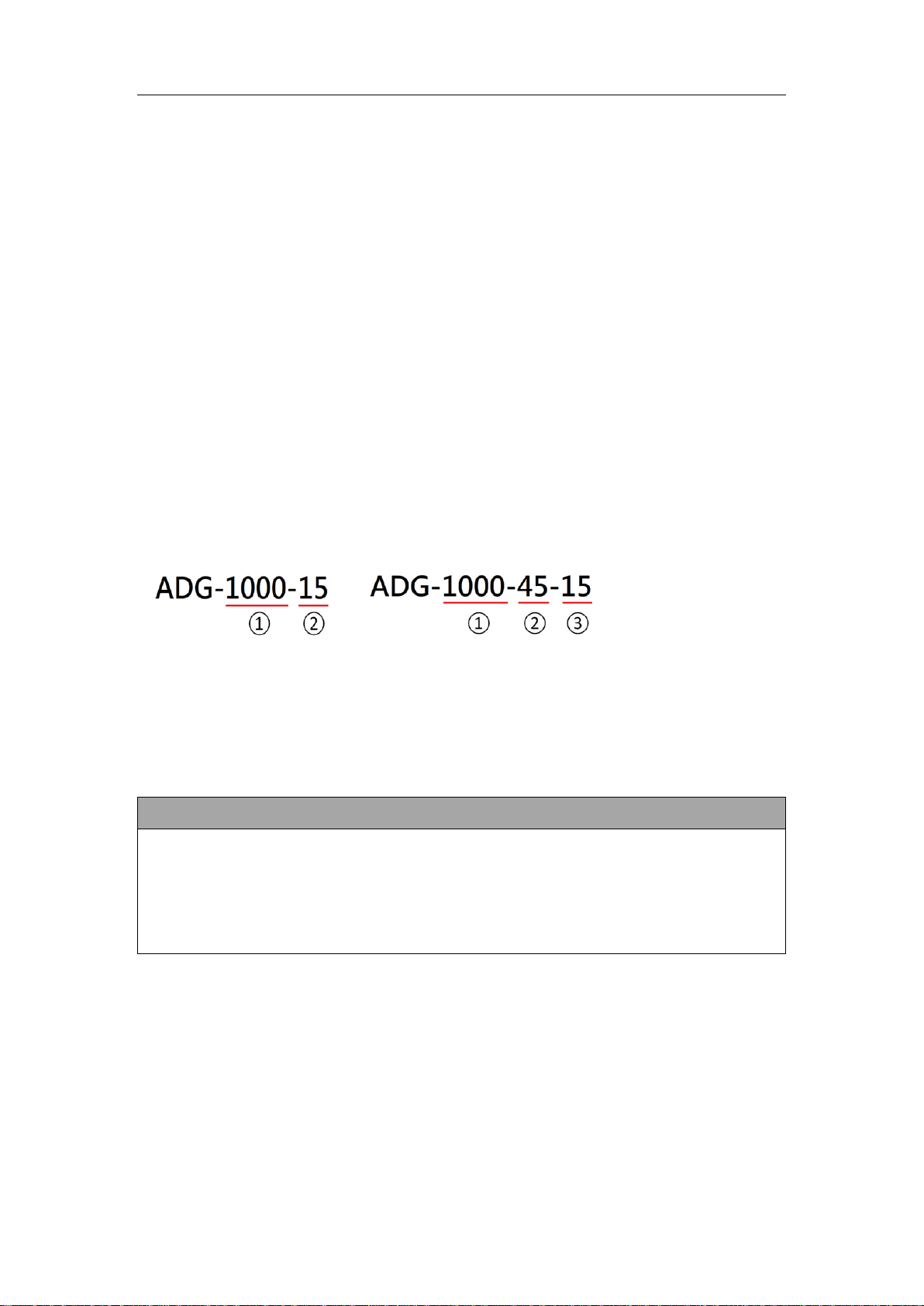
The model naming rule of ADG-L series
①Output voltage: 1000 represents maximum voltage.
②Output current: 15 or 45 represents maximum current.
③Output power: 15 represent maximum power. Only auto-range models have the
number to represent output power on the model name.
Example
Another naming rule example, ADG-L-115-45 which output 115V/45A.
ADG-L-335-15 which output 335V/15A. ADG-L335-45-5 (auto range model) which
output 335V/45A, and maximum power is 5kW. ADG-L-335-90-10 (auto range mod-
el) which output 335V/90 A, and maximum power is 10 kW.

ADG-L Series Programmable DC Power Supply
2
1.1.1 V/I output limit
The following figure shows the V/I limit of the ADG-L series’output, and this can be
applied to standard models and auto-range models of the ADG-L series. Refer to
Fugure 1.1.
Fugure 1.1 V/I output limit for the ADG-L series
1.2 Key Features
A. Configuration
1) Local operation via the touch screen and the rotary knob on the front panel.
2) Remote control via RS-232, RS-485, Ethernet, USB or GPIB.
3) Remote control via analog interface.
4) Protection for OVP, OCP, OPP, OTP, Line OVP, Vin LVP, Vin OVP, Phase loss, and
Fan Error.
B. Input/Output
1) Universal input voltage range, 187~264Vac, single phase; ,187~264Vac,
three-phase connectio; 340~460 Vac, three-phase /four wires Y connec-
tion.,Please refer to Table 1.1, Table 1.2, and Table1.3.
2) Wide output voltage range, max. from 0 to 1000V.
3) High output current up to 135A in one unit.
4) Measurements of voltage (V), current (I), Power (P).
ADG-L ordinary model output V/I curve
(Example: ADG-L-1000-15)
ADG-L auto-range model output V/I curve
(Example: ADG-L-1000-45-15)

ADG-L Series Programmable DC Power Supply
3
1.3 Specifications
Technical specifications of ADG-L series are listed below. All specifications have been
tested according to Preen’s standard test procedures.
Model
ADG-L-115-45
ADG-L-160-32
ADG-L-335-15
ADG-L-335-45-5
Output power
5kW
5kW
5kW
5kW
Input
Input voltage
1Ø 2W+G
187-264 Vac
Input current
30A
Input frequency
47 Hz - 63 Hz
Power factor (PF)
≧0.99 at max. power
Output
Voltage
0~115V
0~160V
0~335V
0~335V
Current
0~45A
0~32A
0~15A
0~45A
CV mode
Voltage ripple (rms)
≦0.25% F.S.
≦0.2% F.S.
≦0.08% F.S.
≦0.08% F.S.
Voltage noice (p-p)
≦1.6% F.S.
≦1.6% F.S.
≦0.8% F.S.
≦0.8% F.S.
Voltage line regulation
≦0.1% F.S.
≦0.1% F.S.
≦0.1% F.S.
≦0.1% F.S.
Voltage load regulation
*1
≦0.3% F.S.
≦0.3% F.S.
≦0.1% F.S.
≦0.1% F.S.
CC model
Current ripple (rms)
≦0.25% F.S.
≦0.2% F.S.
≦0.15% F.S.
≦0.15% F.S.
Current line regultaion
≦0.03% F.S.
≦0.03% F.S.
≦0.03% F.S.
≦0.03% F.S.
Current load regulation
≦0.2% F.S.
≦0.2% F.S.
≦0.2% F.S.
≦0.15% F.S.
Slew rate *2
Rise time
≦25ms
≦25ms
≦30ms
≦30mS
Fall time (Full load)
≦30ms
≦30ms
≦45ms
≦45mS
Fall time (No load)
≦3s
Transient response *3
≦5ms
Programming & Mesurement
Voltage programming accuracy
≦0.08% F.S. +100mV

ADG-L Series Programmable DC Power Supply
4
Table 1.1 Technical specifications
Voltage measurement accracy
≦0.08% F.S. +100mV
Voltage resolution
100mV
Current programming accuracy
≦0.3% F.S. +60mA
Current measurement accuracy
≦0.2% F.S. +60mA
Current resolution
10mA
Power programming accuracy
≦0.4% F.S.
Power measurement accuracy
≦0.4% F.S.
Power resolution
0.01kW
General specs
Efficiency
≧90% at max. power
Interfaces
Standard: RS-485/RS-232 (Modbus) & Analog
Option : Ethernet/USB/RS-485/RS-232 (SCPI) or GPIB
Remote sensing
≦5V
Operating temperature
0°C ~ 40°C
Storage temperature
-20°C ~ 70°C
Protection
OVP、OCP、OPP、OTP、Vin OV、Vin Unbalance、LDC OV
OVP range
0~110% F.S.
OCP range
0~110% F.S.
Dimension (HxWxD)
132 x 442 x 692 mm
Weight
5kW: approx. 19.1kg
*1 The load variation is 0~100% at rated input voltage.
*2 The time required for the output voltage to change from 10% to 90% or 90% to 10% at full scale.
*3 The time required for the output voltage to return to ±1% of the set voltage when the load changes from 50% to 100% or
100% to 50% under fixed input voltage and temperature conditions.
* The above is the specification when the output voltage and current are 1% or more
** The company's products are constantly being developed and improved, and the specifications are subject to change without
prior notice.

ADG-L Series Programmable DC Power Supply
5
Model
ADG-L-115-90
ADG-L-160-63
ADG-L-335-30
ADG-L-335-90-10
ADG-L-500-20
ADG-L-670-15
ADG-L-670-45-10
Output power
10kW
10kW
10kW
10kW
10kW
10kW
10kW
Input
Input voltage
1Ø 2W+G 187-264 Vac, 3Ø 3W+G 187-264 Vac, 3Ø 4W+G 340-460 Vac
Input current
1Ø : 60A, 3ØΔ: 35A, 3ØY : 19A
Input frequency
47 Hz - 63 Hz
Power factor (PF)
≧0.99 at max. power
Output
Voltage
0~115V
0~160V
0~335V
0~335V
0~500V
0~670V
0~670V
Current
0~90A
0~63A
0~30A
0~90A
0~20A
0~15A
0~45A
CV
mode
Voltage
ripple (rms)
≦0.3% F.S.
≦0.3% F.S.
≦0.15% F.S.
≦0.15% F.S.
≦0.08% F.S.
≦0.08% F.S.
≦0.08% F.S.
Voltage
noice (p-p)
≦2.5% F.S.
≦2.5% F.S.
≦1.6% F.S.
≦1.6% F.S.
≦0.8% F.S.
≦0.8% F.S.
≦0.8% F.S.
Voltage line
regulation
≦0.1% F.S.
≦0.1% F.S.
≦0.1% F.S.
≦0.1% F.S.
≦0.03% F.S.
≦0.03% F.S.
≦0.03% F.S.
Voltage
load regu-
lation *1
≦0.3% F.S.
≦0.3% F.S.
≦0.3% F.S.
≦0.3% F.S.
≦0.05% F.S.
≦0.05% F.S.
≦0.05% F.S.
CC
mode
Current
ripple (rms)
≦0.3% F.S.
≦0.2% F.S.
≦0.3% F.S.
≦0.2% F.S.
≦0.5% F.S.
≦0.5% F.S.
≦0.25% F.S.
Current line
regultaion
≦0.1% F.S.
≦0.1% F.S.
≦0.2% F.S.
≦0.2% F.S.
≦0.05% F.S.
+50mA
≦0.05% F.S.
+50mA
≦0.05% F.S.
+50mA
Current
load regu-
lation
≦0.2% F.S.
≦0.2% F.S.
≦0.3% F.S.
≦0.3% F.S.
≦0.25% F.S.
≦0.25% F.S.
≦0.25% F.S.
Slew
rate *2
Rise time
≦25ms
≦25ms
≦30ms
≦30ms
≦55ms
≦60ms
≦60ms
Fall time
(Full load)
≦30ms
≦30ms
≦45ms
≦45ms
≦45ms
≦45ms
≦45ms
Fall time
(No load)
≦3s
Transient response
*3
≦5ms

ADG-L Series Programmable DC Power Supply
6
Programming &
Mesurement
Voltage program-
ming accuracy
≦0.08% F.S. +100mV
Voltage measure-
ment accuracy
≦0.08% F.S. +100mV
Voltage resolution
100mV
Current program-
ming accuracy
≦0.3% F.S. +60mA
Current measure-
ment accuracy
≦0.3% F.S. +60mA
Current resolution
10mA
Power programming
accuracy
≦0.4% F.S.
Power measure-
ment accuracy
≦0.4% F.S.
Power resolution
0.01kW
General specs
Efficiency
≧90% at max. power
Interfaces
Standard: RS-485/RS-232 (Modbus) & Analog
Option : Ethernet/USB/RS-485/RS-232 (SCPI) or GPIB
Remote sensing
≦5V
Operating tempera-
ture
0°C ~ 40°C
Storage tempera-
ture
-20°C ~ 70°C
Protection
OVP、OCP、OPP、OTP、Vin OV、Vin Unbalance、LDC OV
OVP range
0~110% F.S.
OCP range
Dimension (HxWxD)
0~110% F.S.
Weight
132 x 442 x 692 mm
Efficiency
10kW: approx. 26.5kg

ADG-L Series Programmable DC Power Supply
7
Model
ADG-L115-135
ADG-L-
160-94
ADG-L-335-45
ADG-L-
335-135-15
ADG-L-
500-30
ADG-L-
670-23
ADG-L-
1000-15
ADG-L-
1000-45-15
Output power
15kW
15kW
15kW
15kW
15kW
15kW
15kW
15kW
Input
Input voltage
1Ø 2W+G 187-264 Vac, 3Ø 3W+G 187-264 Vac. 3Ø 4W+G 340-460 Vac
Input current
1Ø : 90A, 3ØΔ: 52A, 3ØY : 30A
Input frequency
47 Hz - 63 Hz
Power factor
≧0.99 at max. power
Output
Voltage
0~115V
0~160V
0~335V
0~335V
0~500V
0~670V
0~1000V
0~1000V
Current
0~135A
0~94A
0~45A
0~135A
0~30A
0~23A
0~15A
0~45A
CV mode
Voltage
ripple
(rms)
≦0.3% F.S.
≦0.3%
F.S.
≦0.15% F.S.
≦0.15%
F.S.
≦0.15%
F.S.
≦0.15%
F.S.
≦0.1% F.S.
≦0.1% F.S.
Voltage
noise
(p-p)
≦1.6% F.S.
≦1.6%
F.S.
≦1% F.S.
≦1% F.S.
≦0.8%
F.S.
≦0.8%
F.S.
≦0.5%
F.S.
≦0.5% F.S.
Voltage
line
regula-
tion
≦0.1% F.S.
≦0.1%
F.S.
≦0.1% F.S.
≦0.1% F.S.
≦0.1%
F.S.
≦0.1% F.S.
≦0.1%
F.S.
≦0.1% F.S.
Voltage
load
regula-
tion *1
≦0.2% F.S.
≦0.2%
F.S.
≦0.2% F.S.
≦0.2% F.S.
≦0.2%
F.S.
≦0.2% F.S.
≦0.1%
F.S.
≦0.1% F.S.
CC
Mode
Current
ripple
(rms)
≦0.1% F.S.
≦0.1%
F.S.
≦0.15% F.S.
≦0.1%
F.S.
≦0.25%
F.S.
≦0.25%
F.S.
≦0.5%
F.S.
≦0.25%
F.S.
Current
line
regultat
ion
≦0.05% F.S.
+50mA
≦0.05%
F.S.
+50mA
≦0.05% F.S.
+50mA
≦0.05%
F.S. +50mA
≦0.05%
F.S.
+50mA
≦0.05%
F.S. +50mA
≦0.05%
F.S.
≦0.05%
F.S.
Current
load
regula-
tion
≦0.1% F.S.
≦0.1%
F.S.
≦0.2% F.S.
≦0.2%
F.S.
≦0.3%
F.S.
≦0.3%
F.S.
≦0.3%
F.S.
≦0.3%
F.S.

ADG-L Series Programmable DC Power Supply
8
Slew
rate *2
Rise
time
≦25ms
≦30ms
≦30ms
≦30ms
≦55ms
≦60ms
≦90ms
≦90ms
Fall
time
(Full
load)
≦30ms
≦45ms
≦45ms
≦45ms
≦45ms
≦45ms
≦40ms
≦40ms
Fall
time
(No
load)
≦3s
Response time *3
≦5ms
≦5ms
≦5ms
≦5ms
≦5ms
≦5ms
≦5ms
≦5ms
Programming &
Measurement
Voltage program-
ming accuracy
≦0.08% F.S. +100mV
Voltage measure-
ment accurecy
≦0.08% F.S. +100mV
Voltage resolution
100mV
Current program-
ming accuracy
≦0.4% F.S. +60mA
Current measure-
ment accuracy
≦0.4% F.S. +60mA
Current resolution
10mA
Power program-
ming accuracy
≦0.4% F.S.
Power
measuremnt ac-
curacy
≦0.4% F.S.
Power resolution
0.01kW
General specs.
Efficiency
≧90% at max. power
Interface
Standard: RS-485/RS-232 (Modbus) & Analog
Option : Ethernet/USB/RS-485/RS-232 (SCPI) or GPIB
Remote sensing
Compensation
≦5V
Operating tem-
perature
0°C ~ 40°C

ADG-L Series Programmable DC Power Supply
9
Table 1.2 Technical Specifications
Storage tempera-
ture
-20°C ~ 70°C
Protection
OVP、OCP、OPP、OTP、Vin OV、Vin Unbalance、LDC OV
OVP Range
0~110% F.S.
OCP range
0~110% F.S.
OPP range
0~110% F.S.
Dimension
(HxWxD)
132 x 442 x 692 mm
Weight.
15kW: approx. 31.8kg
*1 The load variation is 0~100% at rated input voltage.
*2 Meaning the time that require for output voltage to change from 10% to 90% or 90% to 10% at full scale.
*3 Meaning the time that require for output voltage to return to ±1% of the set voltage when the load changes from 50% to
100% or 100% to 50% under fixed input voltage and temperature conditions.
* The above specification is when the output voltage and current are 1% or more
** The company's products are constantly being developed and improved, and the specifications are subject to change without
prior notice.

ADG-L Series Programmable DC Power Supply
10
1.4 Exterior
ADG-L series exterior is as below.
(a) Front side of ADG-L with handles
(b) Right side of ADG-L with handles

ADG-L Series Programmable DC Power Supply
11
(With cover)
(c) Rear side of ADG-L
Figure 1.2 Outline drawings of the ADG-L series
Figure 1.3 Outline drawing of the ADG-L series

ADG-L Series Programmable DC Power Supply
12
1.5 Name of Parts
A. Front Panel
Figure 1.4 Front panel
Item
Name
Description
1
Power Switch
Press to turn the device ON/OFF.
2
Touch Screen
To set parameters, configure settings and read meas-
urements.
The touch screen can be operated with a finger or with a
stylus.
3
Rotary Knob
To set parameters, configure settings and read meas-
urements.
Push the knob to confirm the selection or setting.
4
Output & Reset Button
Press the button to enable/ disable/ reset the device
output
Blue light indicates that the output is on. Red light indi-
cates that an error occurs
Table 1.3 Description of front panel
This manual suits for next models
4
Table of contents
Other Preen Power Supply manuals


Popular Power Supply manuals by other brands


Sanela
Sanela SLZ 06 Mounting instructions

2N Telekomunikace
2N Telekomunikace EnergyBank Instructions for use

INIM Electronics
INIM Electronics IPS24060G Installation and Maintenance

Toshiba
Toshiba W7 Series Brochure & specs

Gold Note
Gold Note PSU-10 EVO owner's manual

KNX
KNX Module PS-S.640.30.1 user manual


