Preen AFV-S Series User manual

AFV-S Series
High Performance Programmable AC Power Supply
User Manual
AC Power Corp. (Preen)
V 1.01EN
The information in this document is subject to change without notice.
© AC Power Corp. (Preen). All rights reserved

Legal Notices
The information in this product manual is subject to change without notice.
AC Power Corp. makes no warranty of any kind with regard to this user manual, in-
cluding, but not limited to, the implied warranties of merchantability and fitness for a
particular purpose. AC Power Corp. shall not be held liable for errors contained herein
or direct, indirect, special, incidental or consequential damages in connection with the
furnishing, performance, or use of this material.
Copyright Notices. Copyright 2023 AC Power Corp. (Preen), all rights reserved. Repro-
duction, adaptation, or translation of this document without prior written permission
is prohibited, except as allowed under the copyright laws.

Warranty
Preen’s AFV-S series is warranted against defects in material and workmanship for a
period of one year after date of shipment. Preen agrees to repair or replace any as-
sembly or component found to be defective, under normal use during this period.
Preen’s obligation under this warranty is limited solely to repairing any such product
which in sole Preen’s opinion proves to be defective within the scope of the warranty
when returned to the factory or to an authorized service center. Transportation to the
factory or service center is to be prepaid by the purchaser. Shipment should not be
made without prior authorization by Preen.
This warranty does not apply to any products repaired or altered by persons not au-
thorized by Preen, or not in accordance with instructions furnished by Preen. If the
product is defective as a result of misuse, improper repair, or abnormal conditions or
operations, repairs will be billed at cost.
Preen assumes no responsibility for its product being used in a hazardous or danger-
ous manner either alone or in conjunction with other equipment. High voltage used
in some products may be dangerous if misused. Special disclaimers apply to these
products. Preen assumes no liability for secondary charges or consequential damages
and in any event, Preen’s liability for breach of warranty under any contract or other-
wise, shall not exceed the purchase price of the specific product shipped and against
which a claim is made.
Any recommendations made by Preen for use of its products are based upon tests
believed to be reliable, but Preen makes no warranty of the results to be obtained.
This warranty is in lieu of all other warranties, expressed or implied, and no repre-
sentative or person is authorized to represent or assume for Preen any liability in con-
nection with the sale of our products other than set forth herein.
AC Power Corp. (Preen)
USA
192 Technology Dr., Suite S, Irvine, CA 92618
TEL +1 949-988-7799
Taipei
3F No. 200 Gangqian Road, Neihu Dist., Taipei 114, Taiwan
TEL +886 2-2627-1899 FAX +886 2-2627-1879

SAFETY SUMMARY
The following general safety precautions must be observed during all phases of oper-
ation, service, and repair of this product. Failure to comply with these precautions or
specific WARNINGS given elsewhere in this manual will violate safety standards of de-
sign, manufacture, and intended use of the product.
Preen assumes no liability for the customer‘s failure to comply with these require-
ments.
1) BEFORE APPLYING POWER
Verify that the product is set to match with the power line input.
2) PROTECTIVE GROUNDING
Make sure to connect the product to the protective ground to prevent an electric
shock before turning on the power.
3) NECESSITY OF PROTECTIVE GROUNDING
Never cut off the internal or external protective grounding wire, or disconnect
the wiring of protective grounding terminal. Doing so will cause a potential shock
hazard that may bring injury to a person.
4) DO NOT OPERATE IN AN EXPLOSIVE ATMOSPHERE
Do not operate the product in the presence of flammable gases or fumes.
5) DO NOT REMOVE THE COVER OF THE PRODUCT
Personnel who operate the product must not remove the cover of the product.
Component replacement and internal adjustment can be done only by qualified
service personnel.
WARNING
LETHAL VOLTAGES. The product can supply 440V peak at its output. DEATH on con-
tact may result if either the output terminals or the output circuits connected to the
output are touched when the product output is on.

Table of Contents
1 GENERAL INFORMATION ......................................1
1.1 Introduction 1
1.2 Key Features 2
1.3 Specifications 3
1.4 Exterior 5
1.5 Name of Parts 6
2 INSTALLATION.......................................................9
2.1 Inspection 9
2.2 User Preparation 9
2.2.1 Notice for Installation................................................... 9
2.3 Input Connection 11
2.4 Output Connection 12
2.5 Remote Sense Connection 13
2.6 Power-on Procedures 14
2.7 Product Handle Installation 15
2.8 Interface Card Installation 15
2.8.1 RS232/RS485 9-Pin D-Type Connector..........................16
2.8.2 PLC Remote In & Out Connector ..................................16
2.8.3 Analog Control Interface Card (Optional) .....................17
3 LOCAL OPERATION..............................................21
3.1 General 21
3.2 Operation via the Touch Screen and the Rotary Knob 21
3.3 MAIN Page 23
3.3.1 Output Voltage Range .................................................25
3.4 MENU Page 26
3.5 SETTINGS Page 27

3.5.1 TESTING Subpage ........................................................27
3.5.2 SYSTEM Subpage .........................................................34
3.6 MEMORY PAGE 43
3.6.2 Output Page of MEMORY Feature................................46
3.7 COMMUNICATION Page 49
3.7.1 GENERAL Subpage.......................................................49
3.7.2 ETHERNET Subpage (Opt.) ...........................................50
3.7.3 ANALOG Subpage (Optional) .......................................51
3.8 RESULTS Page 53
3.9 WAVE Page 54
3.10 METER Page 56
3.11 INFORMATION Page 58
3.12 Protection 59
4 CALIBRATION......................................................61
4.1 HI-Range Voltage 310V 64
4.2 LO-Range Voltage 155V 65
4.3 HI-Range Voltage 60V 66
4.4 LO-Range Voltage 60V 67
4.5 HI-Range RMS Current 68
4.6 LO-Range RMS Current 69
4.7 Peak Current 70
4.8 Output Socket Current (Only for AFV-S-5000) 72
5 THEORY OF OPERATION......................................74
6 MAINTENANCE ...................................................75
6.1 Notice for maintenance 75
AFV-S Series High Performance Programmable AC Power Supply
1
1General Information
1.1 Introduction
Preen’s AFV-S series is a programmable AC power supply and precision measurements.
This compact power supply comes in four power levels, 600VA, 1250VA, 2500VA and
5000VA, which provides stable output voltage and output frequency with low distor-
tion. The front panel has both touch screen and rotary knob for setting the product
output, In-built with 20 Memories and 4 Shortcuts, and one of the 4 Shortcuts is se-
lectable, which provide an easy operation and measurement reading display. Remote
control for the product can be accomplished selectively via RS232, RS485, Ethernet(op-
tional) & USB(optional) or Analog(optional).
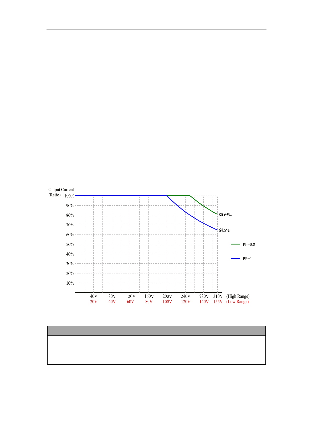
The following figures show the V/I curve according to the AC output of AFV-S Series,
which can be applied to any product model and any output voltage range of the prod-
uct.
Figure 1.1 V/I curve for the AC output of AFV-S series
NOTICE
If the Power Factor (PF) corresponding to the AC output of AFV-S is less than 0.65,
100% output current can be achieved under 0%-100% output voltage, which can
be applied to any AFV-S model and any output voltage range of AFV-S.

AFV-S Series High Performance Programmable AC Power Supply
2
1.2 Key Features
A. Configuration
1. Local operation via the touch screen and the rotary knob on the front panel.
2. Remote control via RS232, RS485, Ethernet (optional) & USB (optional), or Ana-
log(optional) .
3. Protection for OVP, LVP, OCP, OPP, OTP, RCP, Fan Fail and AMP Fail.
4. Temperature-controlled fan speed.
B. Input / Output
1. Selective output voltage range with full scale 310V/Auto.
2. Universal input voltage range 98~132VAC/196~264VAC.
3. Wide output voltage from 0 to 310VAC & output frequency from 40 to 500Hz.
4. Measurement readings of V, I, P, VA, VAR, F, Ipk, CF and PF.
5. Output of Synchronized signal.
AFV-S Series High Performance Programmable AC Power Supply
3
1.3 Specifications
Technical specifications of product are listed below. All specifications have been tested
according to Preen’s standard test procedures.
Model
AFV-S-600
AFV-S-1250
AFV-S-2500
AFV-S-5000
AC Input
Phase
Single
Input Voltage Range
98-132Vac/196-264Vac
196-264Vac (opt.175-235Vac)
Input Frequency
47~63Hz
Max. Current
10A
20A
20A
40A
AC Output
Power (VA)
600VA
1250VA
2500VA
5000VA
Power (W)
500W
1000W
2000W
4000W
Phase
1ϕ /2 Wire + G
Voltage Range
0-155Vrms / 0-310Vrms , user selectable
Voltage Accuracy
±(1% of Setting + 0.1% F.S.)
Voltage Resolution
0.1Vrms
Frequency
40-500Hz
Frequency accuracy
0.2%
Frequency Resolution
0.1Hz
Max. Current (RMS)
5A/2.5A
10A/5A
20A/10A
40A/20A
Max. Current (Peak)
20A/10A
40A/20A
80A/40A
160A/80A
Total Harmonic
Distortion (THD)
0.5%(Resistive Load)
0.3% at 110V/220V, 50Hz, 60Hz.
Line Regulation
0.1V
Load Regulation
0.07% F.S (Resistive Load)
Response Time
300s
Crest Factor
3
Inrush Current
4 times of max. output current (R.M.S)
Measurement
Voltage Range
0-420V
Voltage Accuracy
(0.2% of Reading + 5 Counts)
Voltage Resolution
0.1V
Frequency Range
40.0-500.0Hz
Frequency Accuracy
0.1Hz
Frequency Resolution
0.1Hz
Current Range
Hi: 1-12A/
Hi: 2-24A/
Hi: 0.05-48A

AFV-S Series High Performance Programmable AC Power Supply
4
Lo: 0.005-1.2A
Lo: 0.005-2.4A
Current Accuracy
(1% of Reading + 5 Counts), at 40-500Hz,*2
Current Resolution
Hi: 0.01A / Lo: 0.001A
Hi: 0.01A
Peak Current Range
0-40A
0-80A
0-160A
Peak Current Accuracy
(1% of Reading + 10 Counts), at PF >0.2
Peak Current Resolution
0.1A
Power Range
Hi: 100-1200W/
Lo: 0-120W
Hi: 200-2400W/
Lo: 0-240W
Hi: 0-4800W
Power Accuracy
(2% of Reading + 10 Counts), at 40-500Hz;
Power Resolution
Hi: 1W/Lo: 0.1W
Hi: 1W
General
Efficiency
77% at Max. Power
80% at Max. Power
Protection
OVP, LVP, OCP, OPP, OTP, RCP, Fan Fail and AMP Fail
Remote Interface
Standard: RS232/RS485/PLC Remote In & Out;
Option: Analog Control/Ethernet & USB
Over Current Foldback
(OC-FOLD)
When the OC-FOLD mode is enabled, the criteria to activate/deactivate the OC-FOLD
mode is the set value of the max. output current. The response time from exceeding
the up limit to falling back to the up limit is 1.4S.
Synchronized Signal
ON Mode (5V DC Signal) or EVENT Mode (5V DC Pulse Signal) (BNC type)
Memories
20 Memories
Operating Temperature
0-40C
Dimensions(H×W×D)
88 x 442 x 495mm
88 x 442 x 650mm
176 × 442 × 665mm
3.5 x 17.4 x 19.5inch
3.5 x 17.4 x 25.6inch
6.9 x 17.4 x 26.2inch
Weight
16kg
20kg
31.3kg
61.5kg
35.3lbs
44.1lbs
69lbs
135.6lbs
1. All specifications are subject to change without notice
*2. AFV-S-2500 is ( (1% F.S + 5 Counts)
Table 1.1 Technical specifications

AFV-S Series High Performance Programmable AC Power Supply
5
1.4 Exterior
Product exterior of the AFV-S series are given as follows,
(a) Front-side view of the AFV-S series.
(b) Right-side view of the AFV-S series.
Figure 1.2 Product exterior of the AFV-S series
Figure 1.3 Product exterior of the AFV-S series in axis-side view

AFV-S Series High Performance Programmable AC Power Supply
6
1.5 Name of Parts
A. Front Panel
Figure 1.4 Front panel
Item
Name
Description
1
Power Switch
Press this switch to turn on/ turn off the product.
2
Touch Screen
Touch the screen for setting values, menu, and testing set-
tings.
3
Rotary Knob
Turn or press the rotary knob to for setting values, menu,
and testing settings.
4
Output & Reset Button
Press this button to enable/disable the product output.
⚫When the output is stopped, short press <2 seconds
to restart output.
⚫When the output is stopped, long press ≧2 seconds
to clear the display.
B. Rear Panel
Figure 1.5 Rear panel (for the product model of AFV-S-600)

AFV-S Series High Performance Programmable AC Power Supply
7
Figure 1.6 Rear panel (for the product models of AFV-S-1250)
Figure 1.7 Rear panel (for the product models of AFV-S-2500)
Figure 1.8 Rear panel (for the product model of AFV-S-5000)
AFV-S Series High Performance Programmable AC Power Supply
8
Item
Name
Description
5
AC Output Socket
This socket is used to output AC power to the load.
6
Output Terminals
These terminals are used to output AC power to the load.
7
Remote Sense Connector
These connectors sense directly at the terminals of the load
to compensate any voltage drop on the connecting cable.
NOTICE: Make sure to connect the terminal “SL” of the re-
mote sense connector to the terminal “L” of the load and con-
nect the terminal “SN” of the remote sense connector to the
terminal “N” of the load. Notice that reverse polarity is not
allowed.
8
RS232/RS485 Interface
This interface is used for remote control via the RS232/RS485
cable
9
Input Voltage Selector
Verify this selector is switching to the position (either 115V or
230V) matching the input voltage before switching on the
product.
NOTICE: This function is only available on the product models
of AFV-S-600 and AFV-S-1250.
10
PLC Remote In & Out
These interfaces are used for remote control via PLC.
11
USB Interface
The interface is used for firmware update via the USB cable.
12
Synchronized Signal I/O
This I/O is used to output synchronized signal via the BNC ca-
ble.
13
Input Terminals
(AC Inlet)
These terminals are used to connect the product with the
power line input.
NOTICE: These terminals are replaced by the AC IEC inlet for
the product model of AFV-S-600.

AFV-S Series High Performance Programmable AC Power Supply
9
2Installation
2.1 Inspection
After unpacking the product, please inspect any damage that may have occurred dur-
ing the shipment. Save all packing materials in case the product has to be returned one
day.
If any damage is found, please file a claim with the carrier immediately. Do not return
the product to the factory without obtaining the prior Return Merchandise Authoriza-
tion (RMA) acceptance from Preen.
2.2 User Preparation
Be sure the device is connected to the power line input that meets the specification.
The device must be installed in an air-circulated area, so that the fans built-in are able
to ventilate the heat generated by components properly. The ambient temperature
should be controlled within 40C.
2.2.1 Notice for Installation
1. The device must be installed on horizontal grounds and should be located near
the load so that the connection is as short as possible.
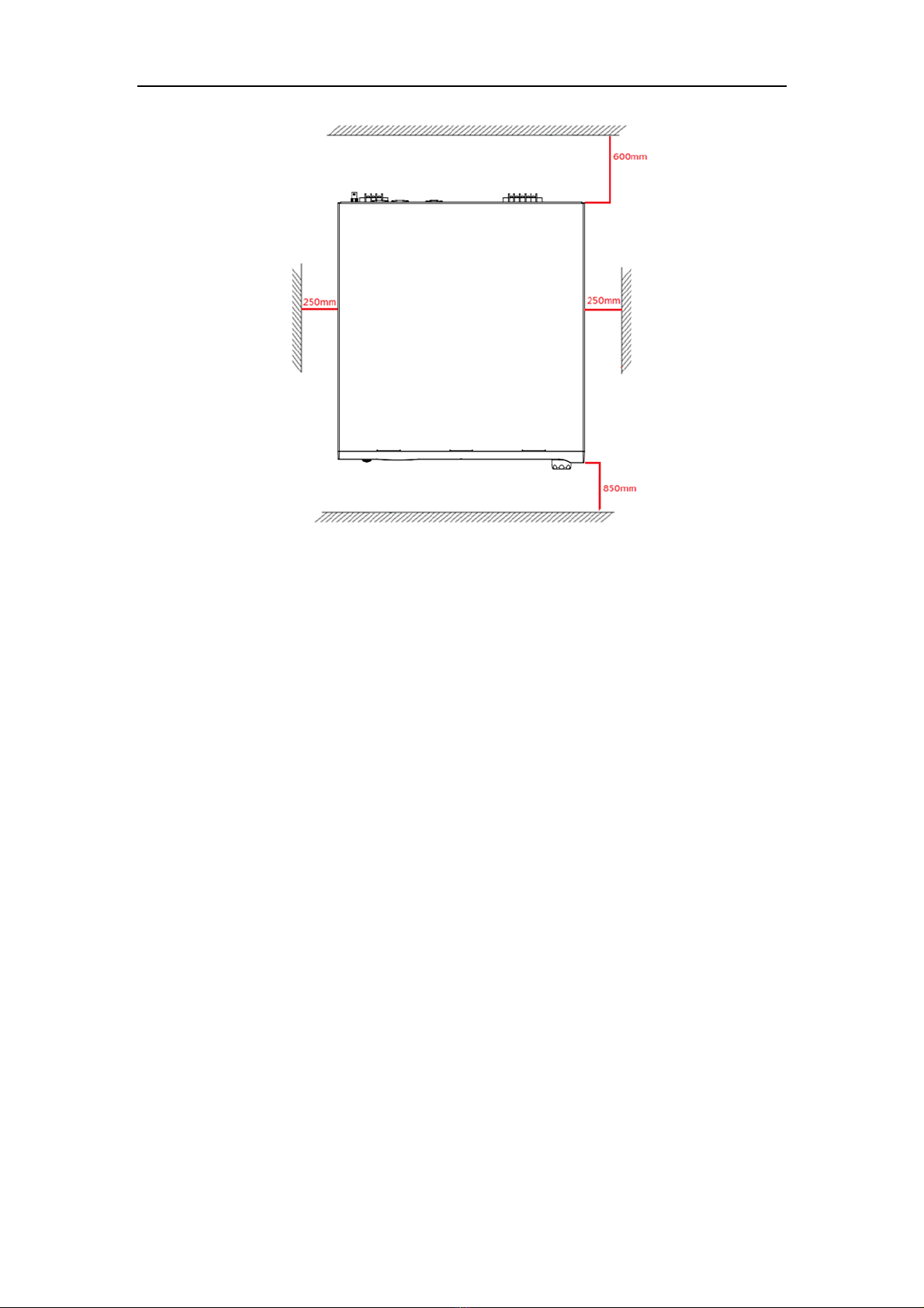
2. Leave sufficient space around the device for ventilation and maintenance (refer
to Figure 2.1). Do not block the cooling fan opening in case of internal tempera-
ture getting too high and having bad impact on product lifespan.
3. The device should be located in proper ventilation. The ambient temperature and
humidity should not be high. Stay away from liquid, flammable gases, corrosive
substances, heat sources, or direct sunlight. Keep the opening free from dust.
4. The operating environment should be free from dust, volatile organic compounds,
high salinity, or corrosive substance.
5. Do not operate the device outdoor.
6. Use correct cable selection and proper power distribution to ensure the safety of
the device and the users.
AFV-S Series High Performance Programmable AC Power Supply
10
Figure 2.1 The required space for the device.

AFV-S Series High Performance Programmable AC Power Supply
11
2.3 Input Connection
The input terminals are located on the rear panel of the product (see Figure 2.2). The
input power cord must be rated at least for 85C. The input power cord must have
rated current which is greater than or equal to the maximum input rated current of
the product.
See Figure 2.2 and do the following procedures step by step:
1. Remove the safety cover from the rare panel of the product.
2. Screw the power cord to the input terminals of the product as follows,
2.1 green or yellow wire to the terminal “G” of the input terminals;
2.2 white or blue wire to the terminal “N” of the input terminals; and
2.3 black or brown wire to the terminal “L” of the input terminals.
3. Slip the safety cover over the input terminals, and secure the cover with two
screws.
WARNING
Protective Grounding. To protect users, the wire connected to terminal “G” (that
is GND) must be connected to the earth ground. Under no circumstances shall this
product operated without an adequate protective grounding connection.
Installation of the power cord to the product must be done by a professional and in
accordance with local electrical codes.
Figure 2.2 Input terminals

AFV-S Series High Performance Programmable AC Power Supply
12
2.4 Output Connection
The output terminals are located on the rear panel of the product (see Figure 2.3). The
terminals “N” and “L” of the output terminals are connected to the load. To match the
safety requirements, the safety cover for the output terminals must be fastened. The
wires to the load must be sufficiently large gauges, so they will not overheat while
carrying the output current.
Figure 2.3 Output terminals
Figure 2.4 Output terminals to the load
AFV-S Series High Performance Programmable AC Power Supply
13
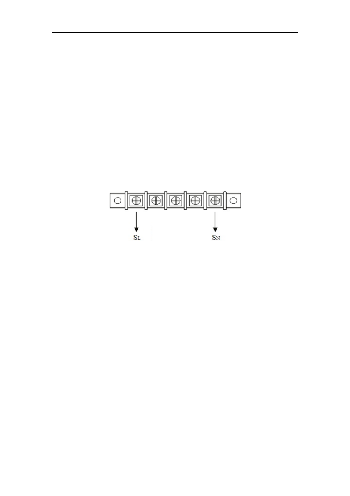
2.5 Remote Sense Connection
The product supports remote sense function, which monitors the voltage at the load
instead of the output terminal of the product. It ensures the delivery of accurate volt-
age as programmed at the load by automatically compensating the output voltage
drop over the connecting cable.
Remove the iron chip from the terminals “SN” and “SL” of the remote sense connector
and connect the terminals of the remote sense connector to the corresponding termi-
nal of the load (see Figure 2.4 & 2.5). Because the sensing leads carry only a few
milliamperes, the sensing leads are much lighter than the load leads. The sensing leads
are part of the feedback path of the product, so they must be kept at a low resistance
to maintain the best performance. The sensing leads must be connected to the load
carefully so that they will not be open-circuited. If the sensing leads are left uncon-
nected or become open-circuited during operation, the product will disable the output.
The sensing leads must be a twisted pair to minimize the interference from external
noise. The sensing leads need to be connected to the load as closely as possible.
Figure 2.5 Remote sense connector

AFV-S Series High Performance Programmable AC Power Supply
14
2.6 Power-on Procedures
WARNING
Before turning on the product, all protective grounding terminals, extension
cords, and devices connected to the product must be connected to a protective
ground. Any disconnection of the protective ground will cause a potential electric
shock hazard that could result in personal injury.
Apply power and press the power switch to turn on the product, then the touch
screen located on the front panel will light up and display the POWER-ON page shown
as below,
Figure 2.6 POWER-ON page
After displaying the POWER-ON page, the MAIN page is shown on the touch screen as
follows, and then users can input programming data or options by either pressing the
touch screen or turning the rotary knob.
Figure 2.7 MAIN page
This manual suits for next models
4
Table of contents
Other Preen Power Supply manuals


