PREFORMED LINE PRODUCTS COYOTE Dome Cross-Connect Closure 6-1/2" x... User manual
1
COYOTE®Dome Cross-Connect Closure 6-1/2" x 17"
FEBRUARY 2015
Be sure to read and completely understand this procedure before applying product. Be sure to select the
proper PREFORMED product before application.
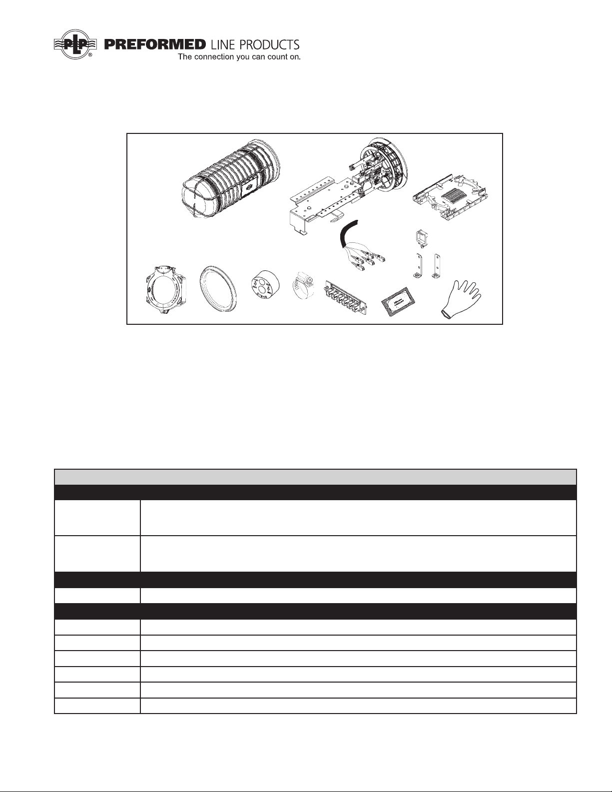
NOMENCLATURE
1. Dome cover (1)
2. Organizer with 4-port
end plate assembly (1)
3. *Splice Tray (Small LITE-GRIP™
tray shown)
4. Dome collar (1)
5. Dome gasket (1)
6. Cable grommets (2)
TOOLS REQUIRED
• 3/8" & 7/16" can wrench
or socket
• 1/4" nut driver or screwdriver
• Snips
• Fiber optic cable opening
tools
7. Hose clamps (4)
8. *Adapter panel
9. Silicone lubricant (4-ve gram packets)
10. Plastic organizer clip (8)
11. Disposable glove (1)
12. *Fiber pigtail kit
13. *Adapter plate brackets (2)
2
*3
*13
*4 56
9
*12
1
10
7
11
*Customer Selected Items
COYOTE Dome Cross-Connect Closure Kits 6.5" x 17" and 6.5" x 22"
Catalog Number Description
800012185 COYOTE Dome Cross-Connect Closure 6.5" x 17" – Includes: (2) Grommets, (1) Cross-Connect Organizer
Assembly with 4-Port End Plate Assembly, (1) Dome, (1) Collar Assembly, (1) Gasket, (8) Plastic Organizer
Clips, (2) Adapter Plate Brackets, (1) Disposable Glove, (1) Silicone Lubricant Packet, & (4) Hose Clamps
800012184 COYOTE Dome Cross-Connect Closure 6.5" x 22" – Includes: (2) Grommets, (1) Cross-Connect Organizer
Assembly with 4-Port End Plate Assembly, (1) Dome, (1) Collar Assembly, (1) Gasket, (8) Plastic Organizer
Clips, (2) Adapter Plate Brackets, (1) Disposable Glove, (1) Silicone Lubricant Packet, & (4) Hose Clamps
Catalog Number Accessory Kits
80808456 COYOTE Dome End Plate Fixture
Catalog Number Mounting Brackets
8003716 Aerial Mounting Bracket (End Plate Mount)
8003831 Aerial Mounting Bracket (Dome Mount)
8003833 Aerial Mounting Bracket for ADSS Applications (Dome Mount)
8003702 Pole/Wall Mounting Bracket
8003835 Universal Mounting Bracket Kit for Hand Hole Applications
8003707 Swing Arm for Hand Hole Applications
*8
2© 2015 Preformed Line Products Company. All rights reserved.
Splice Tray/Closure Capacities for Cross-Connect
Splice Tray
Depth Description
6.5" x 17" 6.5" x 22"
Trays per
Closure
Closure Splice
Capacity
Trays per
Closure
Closure Splice
Capacity
Low Prole Single Fusion 4 48 4 48
24 Count Low Prole Single Fusion N/A N/A 3 72
Standard Single Fusion or Mechanical 3 36 3 36
Ribbon Mass Fusion 2 144 2144
LITE-GRIP Single Fusion 2 80 2 80
LITE-GRIP Mass Fusion 2 360 2 360
COYOTE
®
Dome Cross-Connect Accessories
Catalog Number Description Catalog Number Description
Adapter Plate / Connector Kits
6SMSC Adapter Plate Module, 6 port, SC, SM, ceramic sleeve 6SMFC Adapter Plate Module, 6 port, FC, SM, ceramic sleeve
6SCAPC Adapter Plate Module, 6 port, SC, SM, APC, ceramic sleeve 8SMFC Adapter Plate Module, 8 port, FC, SM, ceramic sleeve
12SMDSC Adapter Plate Module, 12 port, six dual SC, SM, ceramic
sleeve 6FCAPC Adapter Plate Module, 6 port, FC, SM, APC, ceramic sleeve
12MMDSC Adapter Plate Module, 12 port, six dual SC, MM, metal
sleeve 6SMLC Adapter Plate Module, 6 port, LC, SM, ceramic sleeve
8SMSC Adapter Plate Module, 8 port, SC, SM, ceramic sleeve 12SMLC Adapter Plate Module, 12 port, six dual LC, SM, ceramic
sleeve
8SCAPC Adapter Plate Module, 8 port, SCAPC, SM, ceramic sleeve 6MMST Adapter Plate Module, 6 port, ST, MM, metal sleeve
6SMST Adapter Plate Module, 6 port, ST, SM, ceramic sleeve 600 Blank Filler Panel
8SMST Adapter Plate Module, 8 port, ST, SM, ceramic sleeve
Pigtail Accessory Kits
P6SCU3 6 Simplex, 900 Micron, Color Coded, SC, SM, 3 meter P6FC3 6 Simplex, 900 Micron, Color Coded, FC, SM, 3 meter
P12SCU3 12 Simplex, 900 Micron, Color Coded, SC, SM, 3 meter P12FC3 12 Simplex, 900 Micron, Color Coded, FC, SM, 3 meter
P6SCA3 6 Simplex, 900 Micron, Color Coded, SC, SM, APC, 3 meter P12FC5 12 Simplex, 900 Micron, Color Coded, FC, SM, 5 meter
P12SCA3 12 Simplex, 900 Micron, Color Coded, SC, SM, APC, 3 meter P12FCA3 12 Simplex, 900 Micron, Color Coded, FCAPC, SM, 3 meter
P12SCA5 12 Simplex, 900 Micron, Color Coded, SC, SM, APC, 5 meter P6LC3 6 Simplex, 900 Micron, Color Coded, LC, SM, 3 meter
R12SCU3 Ribbon, 12 Fiber, Color Coded, SC, SM, LC, APC, 3 meter P12LC3 12 Simplex, 900 Micron, Color Coded, LC, SM, 3 meter
R12SCA3 Ribbon, 12 Fiber, Color Coded, SC, SM, APC, 3 meter P6STM3 6 Simplex, 900 Micron, Color Coded, ST, MM, 3 meter
P6ST3 6 Simplex, 900 Micron, Color Coded, ST, SM, 3 meter P12SCM3 12 Simplex, 900 Micron, Color Coded, SC, 62.5, 3 meter
P12ST3 12 Simplex, 900 Micron, Color Coded, ST, SM, 3 meter
Splice Trays for COYOTE Dome Cross-Connect Closure Kits 6.5” x 17” and 6.5” x 22”
80807701 Low Prole Splice Tray with plastic splice blocks (12 splice count)
80807531 Low Prole Splice Tray (blank) – no splice blocks (12 splice count)
8003468 24 Count Low Prole Splice Tray with plastic splice blocks (36 splice count)
80806033 Standard Splice Tray with elastomeric splice blocks (12 splice count)
80806182 Standard Splice Tray (blank) – no splice blocks (12 splice count)
80807114 Ribbon Splice Tray with elastomeric splice blocks (72 splice count)
80808160 Ribbon Splice Tray (blank) – no splice blocks (72 splice count)
LGSTS16 LITE-GRIP® Splice Tray with Yellow 8-Hole LITE-GRIP splice blocks – single fusion splices (Splice tray is provided wth splice blocks to support 16
splices but has the capacity for 40 splices). Splice Block Kit (Cat. # LGSBS8-5) is required to achieve maximum tray capacity.
LGSTR144 LITE-GRIP Splice Tray with Purple 3-Hole LITE-GRIP splice blocks – mass fusion/ribbon splices (144 splice count)

3
COYOTE Grommet Chart
For use in COYOTE ONE Dome, Dome, GLC, In-Line RUNT, Terminal, Taut, LCC, & Aerial Drop Closures
PLP Catalog
Number Cable Range Inches (mm) Description Splitting Location
8003701 .42 - .60 (11 - 15 mm) &
.60 - .85 (15 - 22 mm) 2-entry grommet
8003691 .42 - .60 (11 - 15 mm) 1-entry grommet
8003692 .60 - .85 (15 - 22 mm) 1-entry grommet
8003693 .85 - 1.0 (22 - 25 mm) 1-entry grommet
8003694 1.0 - 1.25 (25 - 32 mm) 1-entry grommet
8003663 .42 - .60 (11 - 15 mm) 2-entry grommet
8003990
.50 - .60 (12.7 - 15.2)
.125 - .25 (3.2 - 6.4)
and at drop
4-entry grommet
8003664 .30 - .43 (8 - 11 mm) 4-entry grommet
8004065 .250 - .312 (6.4 mm - 7.9 mm) 4-entry grommet
8003665 .125 - .25 (3 - 6 mm)
and at drop cable 6-entry grommet
8003676
.42 - .60 (11 - 15 mm),
.125 - .25 (3 - 6 mm),
and at drop cable
7-entry grommet
8003677 .125 - .25 (3 - 6 mm)
and at drop cable 8-entry grommet
NOTE: Grommet Kit contains (1) Grommet, (1) Cable Measure Tape, (2) Silicone Lubricant Packs, (1) Set of Plugs
(Multi-Entry Grommets only)

4
Step #1a Remove end plate from organizer
assembly.
Step #1b Remove the end plate caps from the
selected cable ports and break out
the tabs.
PLP Tip:
Scoring edges of tabs with knife
makes them break out easier.
End Plate Preparation
Break out entrance ports 3 and 4
for expressed feeder ber.
Step #1d Break out entrance port 2 for local ber.
Step #2 Optional Step
For better stability during cable instal-
lation and ber splicing, install the end
plate onto the COYOTE®Dome End
Plate Fixure (see Steps 3a-b for
installation details).
Optional Step
Install support bracket onto base.
Position sup-
port bracket
onto base and
secure with
wing nuts.
Note: Do not
tighten wing nut
until end plate is
installed.
Base can be
secured to
work surface
with either
clamps or
with bolts.
Loosen wing
nut so slotted
tab of support
bracket can
slide behind
wing nut.
Step #3b Optional Step
Seat the end plate onto the cushion
wedges and secure the support bracket
to the stud of the end plate.
Hand tighten any loose wing nuts to secure end
plate to xture.
The outside surface of the end
plate must rest against the support
bracket.
Support Bracket
PLP Tip:
Hole in strength member bracket is a guide for
sheath opening.
Step #4 Lay cable into entry point and mark for
grommet and sheath opening locations.
Mark for
sheath
opening
1.75" (45 mm)
Grommet
location
Step #3a
Step #1c

5
Step #6a If using cut cable, insert cable
through grommet. If your application
requires express/balloon/ring cut
cables, see Step 7 for grommet
slitting procedure.
Install plug in
unused port
Diameter
range
top hole Diameter
range bottom
hole
Step #5 Measure cable to determine diameter
and hole location to use in grommet.
Step #6b Installing Figure 8 Style Cables and
Cables with Tracer Wires – Remove
tracer wire or ground wire from the por-
tion of the cable that will be positioned
in the grommet and insert the cable into
the grommet.
Cable with
Tracer Wire
Figure 8
Style Cable
Not Correct
Installation
Correct
Installation
Not Correct
Installation
Correct
Installation
Step #7 Grommet Slitting – If slitting is
required, lay grommet on a stable at
surface. Position utility knife with the
cutting edge against the top surface and
cut through grommet.
Consult grommet chart on page 3 for
slitting locations of all grommets.
PLP Tip: Use a pen to sketch slitting lines on top
surface of grommet prior to cutting.
Not Correct
Slitting Angle Correct
Slitting Angle
Slit
Slit
Step #8a Trim strength members to length.
Prepare feeder and local cable(s) for
cut applications.
Minimum Sheath Opening for
Cut Cable Applications
77" 2.0 m
Buffer (Loose)
Tube Cable
2.5" (6.4 cm)
Strength Member
Step #8b Prepare cable(s) for mid sheath appli-
cations. (Express/Balloon/Ring Cut).
For Applications Where Fiber is
Dedicated to the Splice Point
Sheath Opening 77" (2.0 m)
Fiber/Buffer Tube
Cut Location A (see image above)
Buffer (Loose)
Tube Cable
A
X
77" (2.0 m) OFFICE/C.O.
6
Prepare cable for expressed ber
(buffer tube window cut) applications.
For Applications Where Fiber is
Expressed through the Buffer Tube
Sheath Opening 96" (2.4 m)
Buffer Tube
Opening Location
C (see image
above)
Buffer Tube
Opening
Locations for
Window Cut
C
X
X
C
96" (2.4 m)
OFFICE/C.O.
Step #9 If shielded cable is being used, install
shield connector on shielded cables.
See Step #16 for recommended
bonding practice.
Follow standard company practices.
Step #10a Lubricate the outer surface of the
grommet.
Lubricate seal-
ing surface of
grommet with
silicone lubri-
cant provided.
Step #10b Position grommet in end plate slot.
For Wide Range 2-Hole
Grommets, make sure
arrows are pointing down
when inserting grommet(s).
Do not align grommet slit
with end plate seam.
Step #12
Step #11 Install cable cap and secure with hex
bolts. Tighten bolts by hand evenly
until cable cap is fully seated. (DO
NOT USE POWER TOOLS TO
TIGHTEN BOLTS).
Important Note:
Tighten all unused cable caps.
Complete end plate assembly.
PLP Tip:
To start cable cap bolts, apply
pressure with thumb and line
up bolts with inserts. Engage
1 or 2 threads on one of the
bolts. Repeat the process on
opposite bolt. Alternate tight-
ening until fully seated.
Step #8c
7
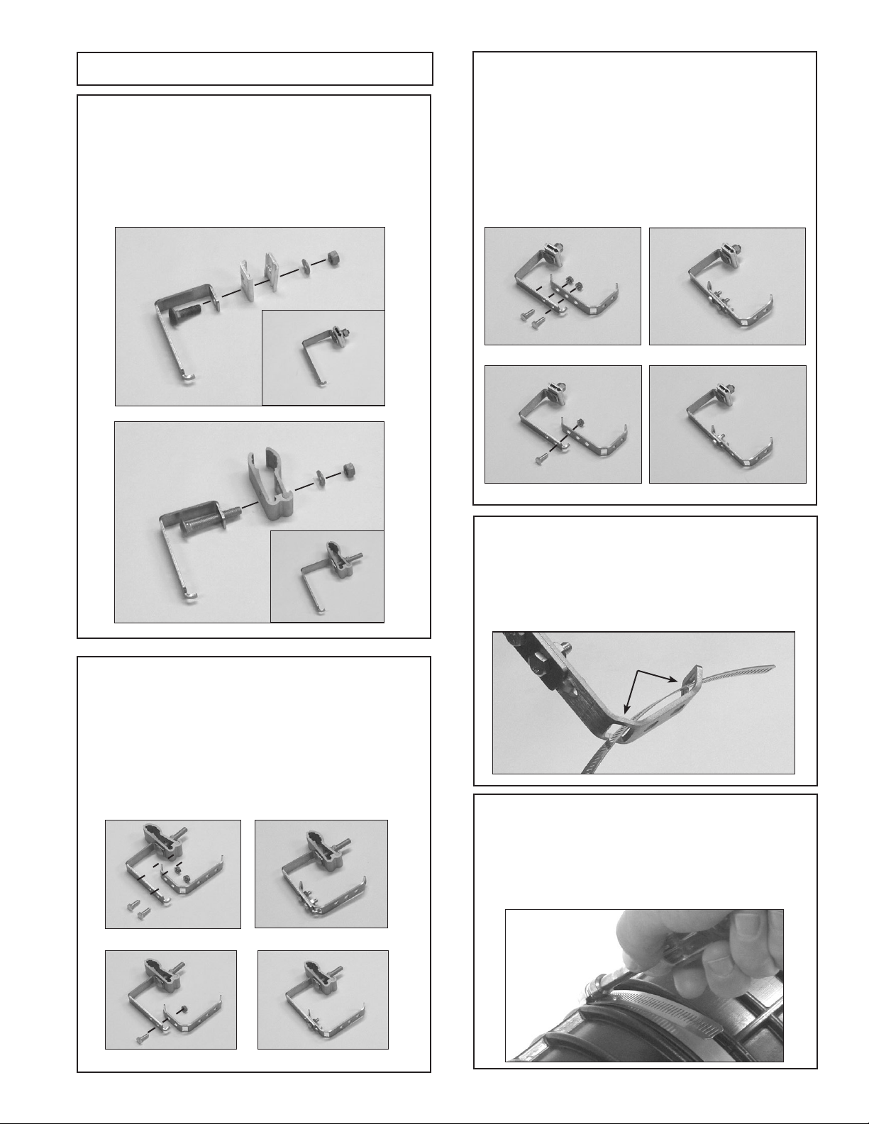
Step #13
Step #14
Step #15
Secure organizer assembly to
end plate with 1/4" hex bolt and
hex nut.
Trim cable strength member(s) even
with the edge of the cable restraint
bracket. Secure strength member(s)
and **KEVLAR®under clip and
tighten screw.
Secure cable sheath with hose
clamp.
PLP Tip:
Avoid contact between hose clamp and shield
connector to maintain isolation of each cable
ground.
Organizer Preparation
Step #16 Attach bonding device between the
cable and ground stud in the end
plate and ground per your accepted
company practice.
Step #18
Step #17 Properly orient brackets. Secure
adapter plate(s) to brackets.
Select adapter plate assembly
location.
Brackets
Adapter plate
**KEVLAR® is a registered trademark of the DuPont™ Company.
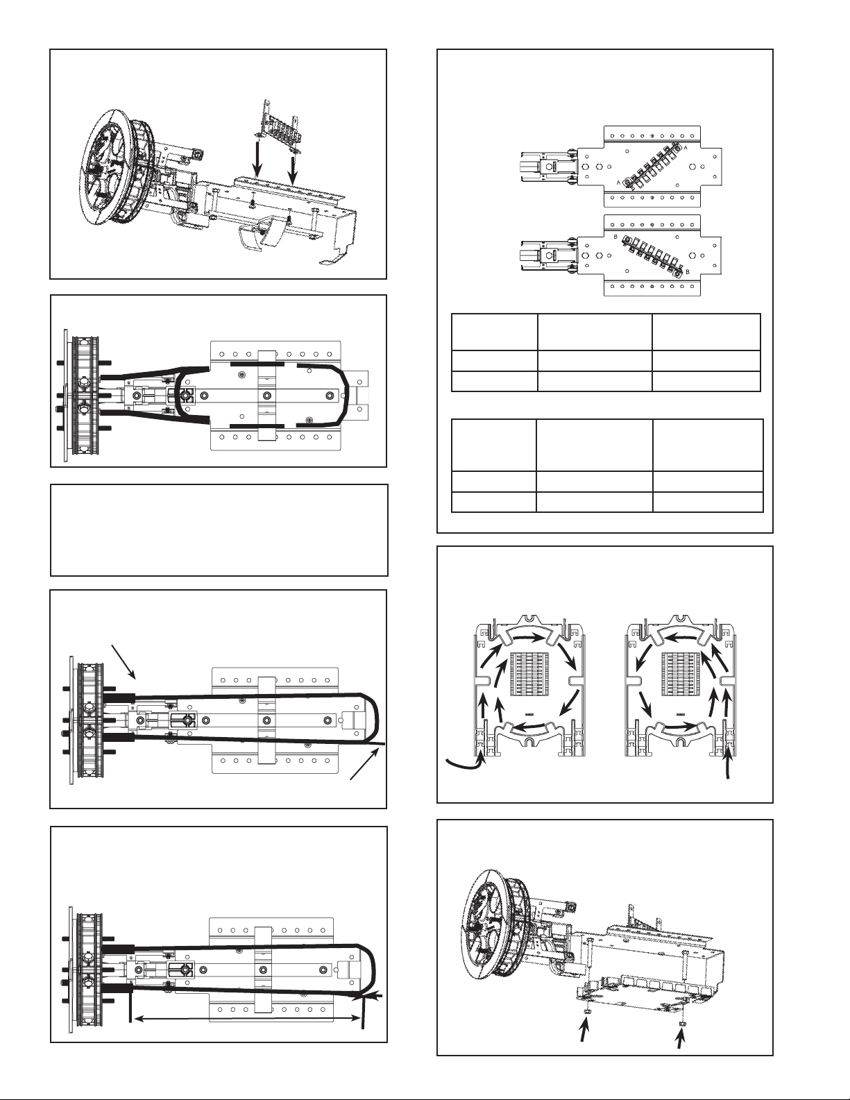
8
Step #24 Install tray(s) onto mounting studs
and secure with nuts. Do not over
tighten nuts.
Step #22 Determine feeder and local pigtail
length based upon adapter plate
location. See charts below.
Plate
Location
Feeder
Pigtail Length
Local
Pigtail Length
A 56" (142 cm) 44" (112 cm)
B 56" (142 cm) 44" (112 cm)
Plate
Location
Yellow Braid
Length Feeder
Pigtails
Yellow Braid
Length Local
Pigtails
A 18-3/4" (48 cm) 9 -1/2" (24 cm)
B 18-3/4" (48 cm) 9-1/2" (24 cm)
Step #21a
Step #20
Select feeder ber to be spliced.
Route and store buffer tubes in
storage brackets.
X
Cut ber to be spliced here
Cut ber
Secure adapter plate assembly to
mainframe with fasteners provided.
Step #21b Measure and mark buffer tube 43"
from cable sheath opening. Remove
buffer tube beyond this mark to
expose ber to be spliced.
43" (109 cm)
Step #23 Route incoming bers and outgoing
pigtails, and splice per standard
company practices.
INCOMING FIBER OUTGOING PIGTAILS
Critical Step:
Position assembly according to image in
Step 21a to insure selected ber is cut at
the proper location.
Step #19
Bottom view of organizer.

9
Step #25 Install storage bracket bar and
secure with nuts.
Step #26 Install organizer clips into desired
holes. Organizer
clips.
Route and install feeder pigtails
to adapter plate.
Step #27b Route and install local pigtails to
adapter plate.
Dome & Collar Installation
Step #29 Slide end plate gasket onto end plate
and press into groove.
Make sure gasket is seated
in groove of end plate
Step #30 Re-tighten all cable cap bolts (step #11) to
assure that the cable caps are fully seated.
When using a can wrench or nut driver, the
installed torque is 35 to 40 in-lbs.
Step #27a
Step #31 Work the gasket into the groove.
Step #32 Position the dome over end plate.
Step #28
Lubricate all inner and outer surfaces of the gasket.
Lubricate all surfaces around gasket
with silicone lubricant to assure easy
assembly and closure re-entry.

10
Step #33 Position the collar at on the work
surface in front of the closure as
shown below.
Step #34 While holding the collar in place,
compress a portion of the end plate
into the dome and insert them in the
groove of the collar near the latch, as
shown below.
Step #35 While holding the collar in place, push
against the end of the dome and
slightly lift and push the other half of
the dome up and over the lip of the
collar with your ngers to fully install
the dome in the collar half.
Step #36 Check to make sure the lip of the
dome is captured within the collar half.
Front Side
Back Side
Lip of dome
is captured
within collar.
Lip of dome
is captured
within collar.
Step #37 Install the other collar half onto
the closure.
Step #38 Secure the collar with the latch and pin.

11
Flash Test Procedure
Step #39 Remove cap from air valve of end plate.
Step #40 Pressurize closure up to a max of 10 psi. Step #42 Release the pressure in the closure
using the bump on the top of the air
valve cap.
Step #41 Spray all sealing surfaces of the
dome end-plate with soapy water to
determine if there are any leaks.

12
Common End Plate Leaks During
Flash Testing
Leak occurring at the corner of the cable
port due to the cap of the cable port not
being fully tightened.
To resolve, remove collar, remove End Plate/
Organizer Assembly from the Dome, and
tighten bolts on end cap where leak occurred.
Reassemble and ash test to conrm that the
leak has stopped.
Leak occurring at the
corner of the cable port
Leak occurring at the cable entry of the
grommet due to the cable not being within the
stated cable diameter range of the grommet
To resolve, remove collar and remove End
Plate/Organizer Assembly from the Dome.
Remove end cap where leak occurred, remove
grommet, remeasure cable with measure
tape provided and select proper grommet.
Reassemble the components and ash test the
closure to conrm that the leak has stopped.
Leak occurring at the cable
entry of the grommet
17.85" (453 mm)
8.57" (218 mm)
10.04" (256 mm)
22.60" (574 mm)
8.57" (218 mm)
13
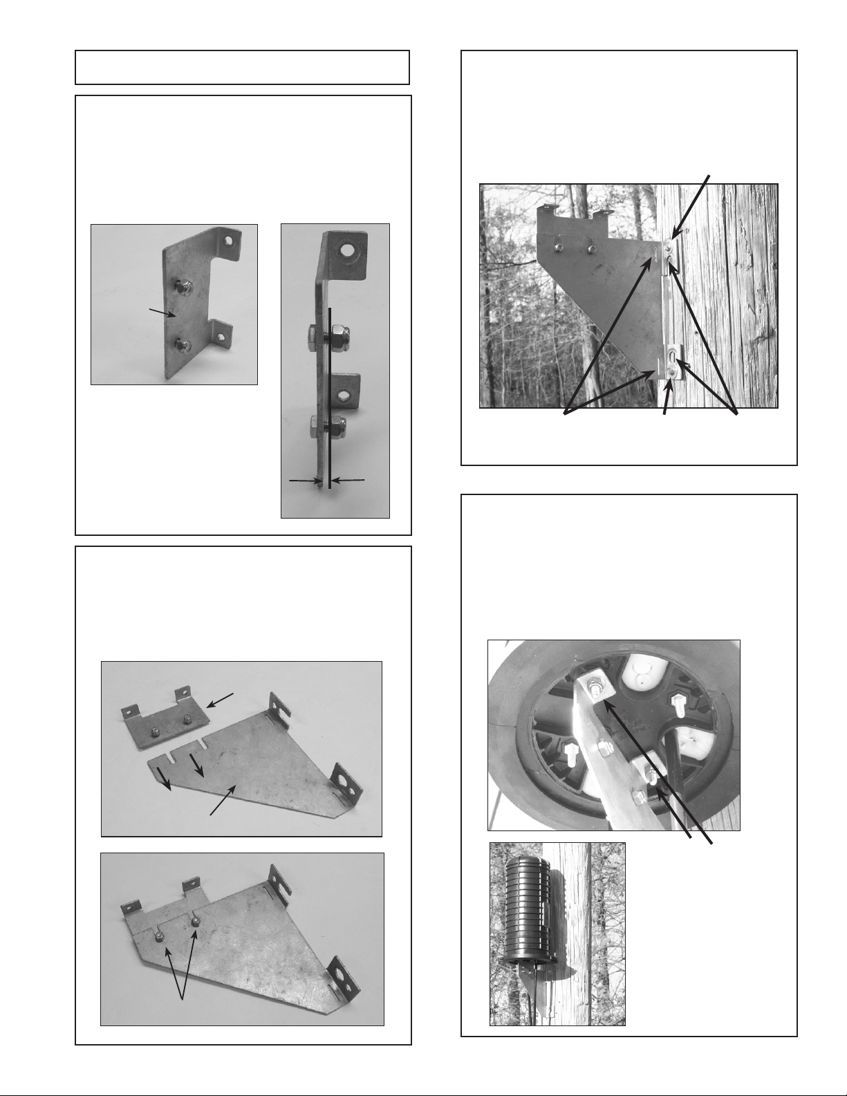
Aerial Mounting Options
Step #43a For 6.5" Dome Strand Mount Aerial
Offset Bracket Kit (P/N: 8004035)
and 6.5" Dome ADSS Mount Aerial
Offset Bracket Kit (P/N: 8004036).
Assemble each bug nut or ADSS
clamp to each top aerial offset
bracket as shown below.
For 6.5" Dome Strand Mount Aerial
Offset Bracket Kit (P/N: 8004035) and
6.5" Dome ADSS Mount Aerial Offset
Bracket Kit (P/N: 8004036).
Step #43b
Strand Clamp
ADSS Clamp
Position 1 – ADSS Clamp Shown
Position 2 – ADSS Clamp Shown
For Shorter Spacing. Align the top aerial offset
bracket with the bottom aerial offset bracket in either
Position 1 or Position 2 as shown below. Secure the
top aerial offset bracket to the bottom aerial offset
bracket with the bolts and keps nuts provided.
For 6.5" Dome Strand Mount Aerial
Offset Bracket Kit (P/N: 8004035)
and 6.5" Dome ADSS Mount Aerial
Offset Bracket Kit (P/N: 8004036).
Step #43c
Position 1 – Strand Clamp Shown
Position 2 – Strand Clamp Shown
For Taller Spacing. Align the top aerial offset bracket
with the bottom aerial offset bracket in either Position
1 or Position 2 as shown below. Secure the top aerial
offset bracket to the bottom aerial offset bracket with
the bolts and keps nuts provided.
Step #44
Slots
6.5" Dome Strand Mount Aerial
Offset Bracket Kit (P/N: 8004035)
and 6.5" Dome ADSS Mount Aerial
Offset Bracket Kit (P/N: 8004036).
Tighten each hose clamp around
the dome.
Step #45
6.5" Dome Strand Mount Aerial
Offset Bracket Kit (P/N: 8004035)
and 6.5" Dome ADSS Mount Aerial
Offset Bracket Kit (P/N: 8004036).
Insert hose clamp through slots in each
of the bottom aerial offset brackets.

14
6.5" Dome Strand Mount Aerial
Offset Bracket Kit (P/N: 8004035)
and 6.5" Dome ADSS Mount Aerial
Offset Bracket Kit (P/N: 8004036).
Bracket installed on dome closure.
Step #46
Strand Aerial
Offset Bracket
shown secured
on a 6.5"
Dome
Step #47
Hand Hole Mounting Option
COYOTE Universal Mounting
Bracket for Hand Hole
Applications (P/N: 8003835).
Secure the Universal Mounting
Bracket to the inner wall of the hand
hole using 2 screws.
Step #48 COYOTE Universal Mounting
Bracket for Hand Hole Applications
(P/N: 8003835).
Insert banding (plastic or metal) through
the slots of the hanger brackets.
COYOTE Universal Mounting
Bracket for Hand Hole
Applications (P/N: 8003835).
Step #49
Position the brackets in the banding channels of
the dome. Tighten the banding until the brackets
are secure.
COYOTE Universal Mounting
Bracket for Hand Hole
Applications (P/N: 8003835).
Step #50
Slide the hanger brackets into the proper
slots of the Universal Mounting Bracket and
snap the hinged lid into place to secure the
hanger brackets.
15
Pole/Wall Mounting Option
The 6.5" COYOTE Dome Pole/Wall
Mount Bracket (P/N: 8003702).
Step #51
Position the bolts through the stud mount plate as
shown, and install lock nuts on bolts until there is
a 1/8" (3 mm) gap between the nut and the stud
mount plate.
The 6.5" COYOTE Dome Pole/Wall
Mount Bracket (P/N: 8003702).
Step #52
Slide the bolts of stud mount plate into the slots
of the pole/wall mount bracket as shown and
tighten the lock nuts until the plates are secure.
Stud Mount
Plate
1/8" (3mm)
Stud Mount Plate
Pole/Wall Mount Bracket
Secure Lock Nuts
The 6.5" COYOTE Dome Pole/Wall
Mount Bracket (P/N: 8003702).
Step #54
Attach the COYOTE Dome closure to the pole/
wall mount bracket by inserting the studs of the
dome closure end plate through the stud holes of
the stud mount plate and securing with the lock
nuts provided.
Secure Lock
Nuts
The 6.5" COYOTE Dome Pole/Wall
Mount Bracket (P/N: 8003702).
Step #53
Attach the dome pole/wall mount bracket to a
pole or wall with either 5/8" through bolts, 1/4"
lag screws, or banding straps.
Banding
Slots
1/4" Lag
Screw Hole
1/4" Lag
Screw Hole
5/8" Through
Bolt Holes

16
SP3074-2
SAFETY CONSIDERATIONS
This application procedure is not intended to supersede any company construction or safety standards. This procedure
is offered only to illustrate safe application for the individual. FAILURE TO FOLLOW THESE PROCEDURES MAY
RESULT IN PERSONAL INJURY OR DEATH.
Do not modify this product under any circumstances.
This product is intended for use by trained technicians only. This product should not be used by anyone
who is not familiar with, and not trained to use it.
When working in the area of energized lines, extra care should be taken to prevent accidental electrical contact.
For proper performance and personal safety, be sure to select the proper size PREFORMED™product before application.
PREFORMED products are precision devices. To insure proper performance, they should be stored in cartons under
cover and handled carefully.
P.O. Box 91129, Cleveland, Ohio 44101 • 440.461.5200 • www.preformed.com • e-mail: inquiries@preformed.com
**KEVLAR® is a registered trademark of the DuPont™ Company.
Step #55b The COYOTE Dome Mount Aerial
Bracket Kit for ADSS (Cat. No.
8003833) can be used to suspend
the COYOTE 6.5" x 17"
or 6.5" x 22" Dome Closure from
ADSS cable. To install the dome
mount aerial brackets, position the
brackets in the banding channels
of the dome and insert banding
(plastic or metal) through the slots
of the brackets. Tighten the banding
until the brackets are secure before
mounting the closure to the ADSS
cable with the ADSS clamp. Banding
Channels
ADSS Clamp
Dome Aerial Hanger Bracket
Strap
Dome Mount Aerial Brackets
COYOTE®Dome Aerial Mounting
Bracket – Dome Mount – for 6.5" x
17" or 22" Dome Closures. The
COYOTE®Dome Mount Aerial
Bracket Kit (Cat. No. 8003831) can be
used to suspend the COYOTE Dome
Closure from the messenger wire. To
install the dome mount aerial brack-
ets, position the brackets in the band-
ing channels of the dome and insert
banding (plastic or metal) through
the slots of the brackets. Tighten the
banding until the brackets are secure
before mounting the closure to the
messenger wire with the bug nuts of
the brackets.
Step #55a Bug Nut
Dome Aerial Hanger Bracket
Strap
Dome Mount Aerial Brackets
Banding Channels
This manual suits for next models
2
Table of contents


