PREFORMED Outside Plant Series User manual

1
COYOTE®HI-COUNT CLOSURE
FOR UNDERGROUND, AERIAL, AND BURIED SPLICES
NOVEMBER 2001
CONTENTS PAGE
1. NOMENCLATURE ..................................... 2
2. DESCRIPTION & CAPACITIES ............. 2,3
3. DETERMINING BLADE
SIZE AND LOCK-TAPE™
SEALANT REQUIREMENTS ................... 3
4. END PLATE PREPARATION—
CUTTER SET-UP....................................... 3
5. END PLATE PREPARATION—
DRILLING ............................................ 3,4,5
6. END PLATE PREPARATION—
LOCK-TAPETM SEALANT
APPLICATION ........................................... 5
7. CABLE PREPARATION—
APPLYING LOCK-TAPETM TO
CABLES FOR FIELD-DRILLED
END PLATES.......................................... 5,6
8. END PLATE ASSEMBLY........................ 6,7
9. BONDING AND/OR GROUNDING
CABLES WITH METALLIC
COMPONENTS ......................................... 7
CONTENTS PAGE
Be sure to read and completely understand this procedure before applying product. Be sure to select
the proper PREFORMED™ product before application.
10. INSTALL ORGANIZER ASSEMBLY ......... 7
11. ROUTING BUFFER TUBES
TO SPLICE TRAYS ................................... 7
12. SECURING BUFFER TUBES
AND ROUTING FIBERS
IN SPLICE TRAYS............................. 8,9,10
13. INSTALLING THE SHELLS .................... 10
14. UNDERGROUND INSTALLATION...........11
15. AERIAL INSTALLATION ..........................11
16. EXTERNAL BONDING .............................11
17. MAINTENANCE PROCEDURES .............11
18. SAFETY CONSIDERATIONS.................. 12
2
3.
1.
2.
4.
5.10.
9.
8.
7.6.
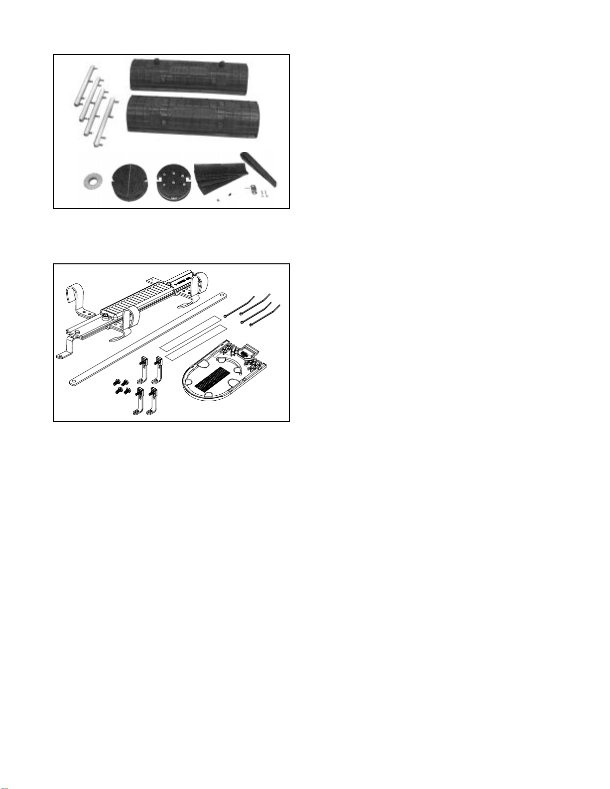
1.00 NOMENCLATURE (See Figures 1&2):
1. Bolt Bars
2. Shell Halves
3. 3/4" LOCK-TAPE™ Sealant
4. End Plates
5. LOCK-TAPE Sealant Strips
6. Cap/Blank Cap (shell kit w/air flange only)
7. Cable Mea-SURE™ Tape
8. Aerial Hanging Brackets
9. Bond Clamp
10. Emery Cloth
FIGURE 1 - COYOTE CLOSURE
COMPONENTS (TYPICAL)
1. “L” Brackets
2.Top Run Torque Bar
3. Buffer Tube Storage and Splice Tray Rack
4. Splice Tray Kit with Clear Cover, Felt Strips, and
Tie Wraps(1)
NOTES:
1. Splice Trays sold separately.
FIGURE 2 - COYOTE HI-COUNT CLOSURE
BUFFERTUBE STORAGE ASSEMBLY AND
RELATED COMPONENTS
1.01 The COYOTE®HI-Count Closure contains
everything needed for installation except
hand tools, vinyl tape, filled cable cleaning fluid,
and C-Cement.
1.02 Tools Needed:
— Splicer’s scissors
— Splicer’s knife
— Tabbing shears
— Common screwdriver
— 1/2" deep well socket*
— 3/8" nutdriver or socket
— Needlenose pliers
— Buffer tube removal tool and/or slitter
— Sidecutters
— Torque Wrench (inch pound readings)*
— Power End Plate Cutter*
*Available from Preformed Line Products
2.00 DESCRIPTION
2.01 For Safety Considerations, refer to section
18.00 of this procedure.
2.02 The COYOTE Hi-Count Closure is specifi-
cally designed for organizing and protecting
the buffer tubes (loose tubes) and individual fiber
splices of high count (up to 432 fibers), loose tube
optic cables.
2.03 The unique buffer tube management system
and inclined, snap-in splice tray arrangement
combine to provide space for splicing up to 432
individual fibers in a compact 9.5" X 28" (241.3 mm x
711.2 mm) Closure. The COYOTE Hi-Count Closure
will accommodate up to 18 individual 24 count
Splice Trays.
2.04 The COYOTE Hi-Count Closure End Plates
have cable capacity for six cables with
L-Bracket supports (Figure 3).
©2001 Preformed Line Products Company. All rights reserved.

3
FIGURE 3 - END PLATE CAPACITY
(VIEW FROM INSIDE END PLATE)
NOTE: An additional 3.0" (76.2 mm) of space is
available on each seam of the COYOTE
Hi-Count Closure. However provisions for
securing the L-Brackets are only provided for
six entries as shown in Figure 3.
3.00 DETERMINING BLADE SIZE AND
LOCK-TAPE SEALANT REQUIRE-
MENTS
3.01 The CABLE Mea-SURE Tape is used to de-
termine the correct Power End Plate Cutter
blade size and the required layers of LOCK-TAPE
Sealant.
3.02 To use CABLE MeaSURE Tape:
— Wrap it around the cable tightly. (Figure 4)
— The index line will point to a letter and
number.
— The letter indicates the correct blade size.
— The number indicates the correct number
of layers of half-lapped LOCK-TAPE
Sealant. (Figure 4)
FIGURE 4 - WRAP CABLE MEA-SURE TAPE
AROUND CABLE
NOTE: If the index line falls on a line between two
numbers, always use the number to the right of
the line. (Figure 5)
FIGURE 5 - SKETCH OF CABLE MEA-SURETAPE
CAUTION: Cable may vary in diameter from place to
place along its length, so be sure to measure
each cable at the area where the End Plate is
to be placed.
4.00 END PLATE PREPARATION -
CUTTER SET-UP
4.01 When using blades A-D, install the blade
directly into the chuck. For blades E-DD, first
install blade into drill adapter.
4.02 Secure blade or adaptor into drill chuck.
Tighten drill chuck in all three locations.
CAUTION: To prevent blades from coming in
contact with base of Power End Plate Cutter,
insure that blade or adapter is inserted as far
into the drill chuck as possible.
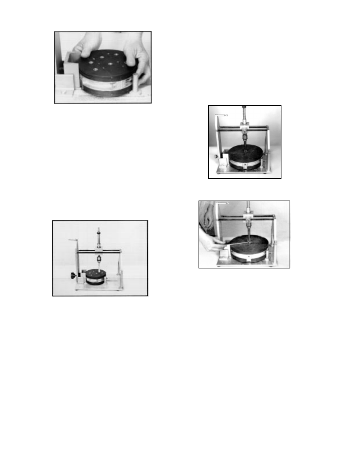
4.03 Insert stop-posts in tapped holes in base of
cutter corresponding to the 9.5" (241.3 mm)
End Plate diameter and hand tighten firmly.
(Figure 6)
FIGURE 6 - PUT STOP POSTS INTO CUTTER
5.00 END PLATE PREPARATION -
DRILLING
5.01 Locate the designated drill marks on the End
Plate (highlighted in yellow). These marks
should face up when placing End Plate in the Power
End Plate Cutter. (Figure 7)
9.5" (241.3 mm) DLX
THREE-SECTION
END PLATE
3 ENTRIES
PER SEAM
MAX. DIA.
1.1" Use D blade and
one half-lap of
LOCK-TAPETM
Sealant.
Use D blade and
one half-lap of
LOCK-TAPETM
Sealant.
Use M blade and
two half-laps of
LOCK-TAPETM
Sealant.
Use O blade and
two half-laps of
LOCK-TAPETM
Sealant.
The shaded area = two half laps. The clear area = one half lap.
4
FIGURE 7 - END PLATE SHOWING THE
DESIGNATED DRILL MARKS
5.02 To enable bonding/strain relief brackets to be
properly applied, the cable holes must be
drilled at the designated drill marks highlighted in
yellow.
5.03 To position End Plate in the cutter:
— Rotate End Plate and slide bearing block
along the guides until the drill is positioned over
designated drill marks.
— Then, tighten the clamp screw and
thumbscrew on the bearing block. (Figure 8).
FIGURE 8 - BLADE POSITION
CAUTION: A small nylon pellet backs up the
thumbscrews in the bearing block. Using
cutter with pellet missing could cause damage
to the guide rails.
To prevent damage, remove the thumbscrews and
insert a small piece of cable sheath. Additional nylon
pellets are available from PLP®.
5.04 Mount a 3/8" drill, drill blade adapter, and one
1/2" deep well socket to the upper end of the bearing
block shaft.
PLP TIP: A special drill motor is available from
Preformed Line Products. No matter what type
of electric drill you use, be sure to press down on
the body of the drill so that pressure is not
exerted sideways on the shaft. This will result in
a much longer life of the bearing blocks. Drill
through the End Plate slowly.
5.05 When using blades E-DD in the drill adapter,
cut through the black plastic of the End Plate
until foam is just visible in the outer ring. (Figure 9)
Use a screwdriver to pop out the plastic disk (not
necessary for A-D drill bits). (Figure 10)
FIGURE 9 - CUTTING THROUGH PLASTIC SHELL
FIGURE 10 - REMOVING PLASTIC DISK
5.06 Drill through the End Plate until the shaft
bottoms out on the stop collar. When the
drill has bottomed out, stop the drill.
CAUTION: Never bring the blade back up through
End Plate while it is still turning. This could
result in an oversized hole. Do not exert
sideways pressure on drill shaft, it may cause
damage to the bearing block.
5.07 If additional holes are needed, repeat
preceding steps 5.03 - 5.06.(Figure 11)

5
FIGURE 11 - END PLATE WITH HOLES DRILLED
5.08 Remove the End Plate from the cutter and
disassemble End Plates by removing both bolts.
6.00 END PLATE PREPARATION -
LOCK-TAPE SEALANT
APPLICATION
6.01 Remove sharp edges on plastic and foam in
area of opening with emery cloth (provided).
(Figure 12)
SCUFF LIGHTLY.
DO NOT REMOVE TOO MUCH MATERIAL
FIGURE 12 - SCUFFING CABLE OPENINGS
PLP TIP: This simple operation will help prevent
catching the LOCK-TAPE Sealant when drawing
the End Plates together. ONLY USE EMERY
CLOTH PROVIDED FOR THIS PROCEDURE.
6.02 Apply a thin coat of C-Cement to each inside
surface of the End Plate sections.
6.03 When the C-Cement becomes tacky, remove
protective backing from a strip of LOCK-
TAPE Sealant.
PLP TIP: Use removed backing from a LOCK-
TAPE Sealant strip to dry and remove excess C-
Cement applied to End Plate. (Figure 13)
FIGURE 13 - C-CEMENT ON END PLATE
6.04 Without stretching, apply LOCK-TAPE
Sealant over prepared surface of the End
Plates, following the contour of the cable holes.
Allow approximately 3/4" (19.05 mm) of LOCK-TAPE
Sealant to extend beyond each end of the End Plate.
This will serve as a tighting indicator during the End
Plate assembly.
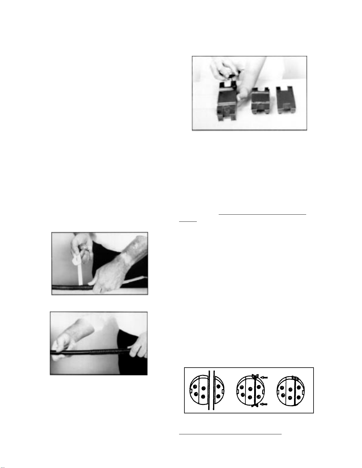
6.05 Square cut the tape away from the bolt
holes. (The area just beyond the metal
insert.) (Figure 14)
FIGURE 14 - SQUARE CUT BOLT HOLES
7.00 CABLE PREPARATION - APPLYING
LOCK-TAPE SEALANT TO
CABLES FOR FIELD-DRILLED END
PLATES
7.01 Measure and mark the cables at 80" (2.03 m)
for the opening of the sheath.
7.02 Remove the cable sheath to open the
appropriate amount of cable. Remove any
other coverings to expose the buffer tubes in the
center of the cable.
7.03 The cable must now be marked for the
installation of the LOCK-TAPE Sealant.
6
— For cables with metallic components, the cable
must be marked in two places. Measuring from the
opened cable end, make one mark at 1.5" (38.10
mm) and the second at 5.5" (139.7 mm).
— For cables without metallic components, only one
mark is required. Again measuring from the opened
cable end, make one mark at 4" (101.6 mm).
Now that the cable is marked, take the emery cloth
provided and scuff the cable between the marks for
cables with metallic components and from the open
end of the cable to the mark for dielectric cables.
Always scuff around the cable, never scuff length-
wise.
7.04 Coat the scuffed area of the cable with C-
Cement and allow to dry to tacky base.
7.05 Apply required number of half lapped layers
of 3/4" (19.05 mm) LOCK-TAPE Sealant
around the cable in the area coated with C-Cement.
Stretch tape while applying. (Figure 15)
PLP TIP: Stretch tape enough to reduce its width
to 1/2" (12.7 mm). Figure 16 shows the com-
pleted application of one half-lapped layer of
LOCK-TAPE Sealant.
FIGURE 15 - APPLYING LOCK-TAPE SEALANT
FIGURE 16 - COMPLETED LOCK-TAPE SEALANT
APPLICATION
8.00 END PLATE ASSEMBLY
8.01 Using the hex bolts provided, fasten the “L”
bracket and retaining clip to the End Plate.
8.02 Before installing prepared cables into End
Plate halves, apply 1/4" (6.35 mm) wide bead
of C-Cement adjacent to the drilled hole. (Figure 17)
FIGURE 17 - BRUSH C-CEMENT OVER LOCK-
TAPE SEALANT
NOTE: If cables being placed in End Plate require
bonding and/or grounding, review Section 9.00
before installing End Plate.
8.03 Position prepared cables into lower End
Plate section, allowing 1/2" (12.7 mm) of the
LOCK-TAPE Sealant to extend beyond the inside of
the End Plate. THIS IS A CRITICAL MEASURE-
MENT.
8.04 For cables containing non-metallic strength
members, insert strength members into
retainer clip and tighten. Cut off excess strength
member.
8.05 Where applications dictate, position prepared
cables into upper End Plate seam per step
8.03 and insert End Plate bolts.
8.06 Using a socket and ratchet, tighten each bolt
evenly in rotation 2 to 3 turns at a time.
CAUTION: Do not use power tools for this operation.
8.07 While tightening, the excess LOCK-TAPE
Sealant extending from the End Plate section
will fold back. When the LOCK-TAPE Sealant stops
moving (folds back), the bolts are sufficiently tight.
(Figure 18)
FIGURE 18 - TAPE FOLDING BACK
CAUTION: DO NOT OVER TIGHTEN!
7
8.08 Trim excess LOCK-TAPE Sealant to within
1/8" (3.18 mm) of the End Plate. DO NOT
STRETCH TAPE DURING TRIMMING PROCESS.
9.00 BONDING AND/OR GROUNDING
CABLES WITH METALLIC COMPO-
NENTS
NOTE: Installation of bonding and grounding
components may be easier if installed prior to
placing cables into End Plate.
9.01 If cable contains a metallic shield, install
shield connector and/or bonding assembly per
company instructions. A shield connector is available
separately from PLP under Catalog No. 80803989.
FIGURE 19 -BONDING ASSEMBLY
9.02 After the bond connector is installed on the
cable and the cable placed in the End Plate
next to the appropriate “L” bracket, attach the bond
connector to the “L” bracket through the slot pro-
vided.
9.03 If cable contains a strength member, insert
the strength member into the retainer clip
and tighten. Cut off excess strength member.
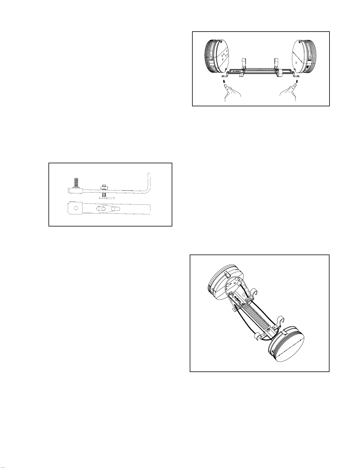
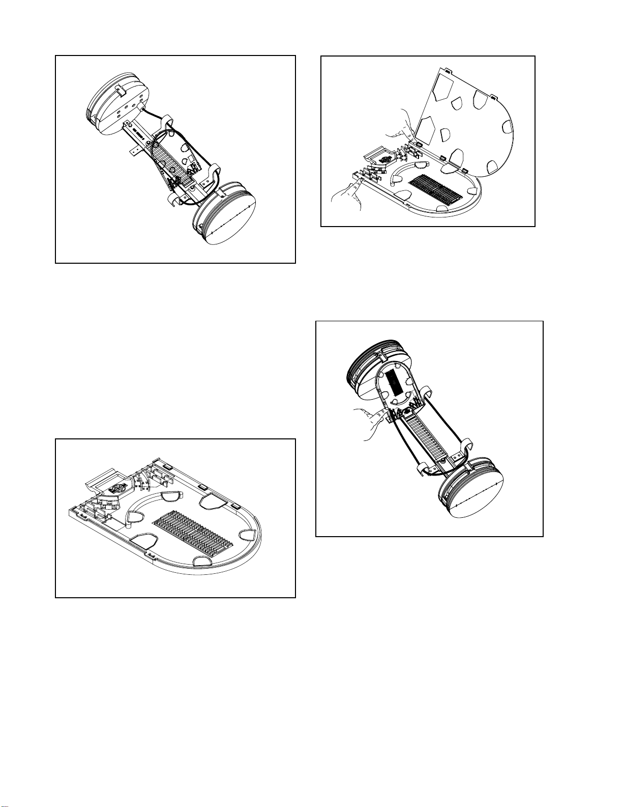
10.00 INSTALL ORGANIZER ASSEMBLY
10.01 Remove the torque bar attachment bolt from
the End Plate and secure the Buffer Tube
Storage and Splice Tray Rack Torque Bar to the End
Plate. (Figure 20)
FIGURE 20 - BUFFERTUBE STORAGE AND
SPLICE TRAY RACK ASSEMBLY SECURED TO
END PLATES
11.00 ROUTE BUFFER TUBES TO
SPLICE TRAYS
11.01 Route buffer tubes as follows:
— Buffer tubes for the back nine splice trays are to
be routed beneath the Splice Tray Rack Assembly
through the buffer tube storage clips as shown in
Figure 21.
— Buffer tubes for the front nine splice trays are to
be routed above the Splice Tray Rack Assembly
through the upper buffer tube storage clips as shown
in Figure 22.
FIGURE 21 - ROUTING OF BUFFER TUBES FOR
BACK SPLICE TRAYS
8
FIGURE 22 - ROUTING OF BUFFER TUBES FOR
FRONT SPLICE TRAYS
12.00 SECURING BUFFERTUBES AND
ROUTING FIBERS ON SPLICETRAYS
12.01 The trays to be used in the COYOTE Hi-
Count Closure are single fiber trays designed
for single fusion heat shrink protected splice applica-
tions. These trays can accommodate up to 24 single
fusion heat shrink protected splices. (Figure 23)
FIGURE 23 - COYOTE HI-COUNT SPLICE TRAY
12.02 Open cover of splice tray. Note that the cover
is hinged on the right side and has two
locking points on the left-hand side. (Figure 24)
FIGURE 24 - REMOVE SPLICE TRAY COVER
12.03 Position the back splice tray on the Splice
Tray Rack and route the buffer tubes into the
LEFT corner of the splice tray. Mark the buffer tubes
just beyond the tie down holes. (Figure 25)
FIGURE 25 - MARK THE BUFFER TUBES
12.04 Remove the buffer tube to the mark and
thoroughly clean the fibers per standard
company practices.
12.05 Apply a wrap of blue felt over the buffer tube
at the end where they will be tied down.
12.06 Position the buffer tubes onto the splice tray
so that they extend 1/4" (6.35 mm) past the
tie down holes and apply provided tie wraps as
shown in Figure 26 A & B.
PLP TIP: For easy tie wrap installation, insert the
tie wrap with the ridges on the inside of the loop,
with the head opposite the notch in the splice

9
FIGURE 27 - ROUTING FIBERS FROM THE
OFFICE BUFFER
12.08 Route fibers 1-12 of the field buffer tube
1-1/2 times counter-clockwise around the
splice tray entering the upper splice block from the
right side. Route fibers 13-24 of the field buffer tube
1-3/4 times counter-clockwise around the splice tray
entering the lower splice block from the left.
(Figure 28)
FIGURE 28 - ROUTING FIBERS FROM THE
FIELD BUFFER
12.09 Splice fibers according to accepted company
practices.
tray. Insert the tail into the head. Press head
down to the tray and hold in place while pulling
the tail to tighten the tie wrap.
FIGURE 26A - INSERT TIE WRAPS
FIGURE 26B - POSITION AND SECURE
BUFFER TUBES
12.07 Route fibers 1-12 of the office buffer tube
1-1/4 times clockwise around the splice tray
entering the upper splice block from the left side.
Route fibers 13-24 of the office buffer tube 1-3/4
times clockwise around the splice tray entering the
lower splice block from the right. (Figure 27)

10
13.01
13.00 INSTALLING THE SHELLS
13.02
13.03
For aerial suspension, attach aerial suspension plates to
bolt bars before installation on shells.
For Manhole Support Bracket applications, attach support tees to
Bolt Bars.
13.05
13.04
Cap With Air Valve
Install SolidCap
After Flash Test
Flash Test To
10 PSI (Max) (69 Kpa)
A
B
First
Then
Finally
Hand Tighten in Sequence with Ratchet (All #1 Bolts
First, Followed by all #2 Bolts, and so on...
Torque Each Bolt Following the Sequence to 125 in.-lbs.
(14 N.m) (90 in.-lbs.(10 N.m) for 4” Closure)
Wait 15 Minutes then Re-Torque all Bolts to 125 in.-lbs.
(14 N.m) (90 in.-lbs.(10 N.m) for 4” Closure)
DO NOT Line Up Shell Seams with End Plate Seams
12344321
12344 321
12.10 Close the splice tray cover and place the tray
in the Splice Tray Rack.
12.11 Repeat steps 12.02 through 12.10 for the
remaining splice trays.

11
14.00 UNDERGROUND INSTALLATION
14.01 The Closure should be installed between
the manhole racks.
14.02 COYOTE Closures are very light and will
float in a water-filled manhole.They must be
tied down.
NOTE: It is recommended that the PREFORMED
Manhole Support, Catalog No. 8003527, be
used to support and tie down the Closure.
15.00 AERIAL INSTALLATION
15.01 For aerial applications, use the Adjustable
Aerial Hanger Bracket Kit (Catalog No.
8003426).
15.02 Be sure all nuts and washers are in their
proper position. Tighten nuts securely.
16.00 EXTERNAL BONDING
External bond methods will be described, but com-
pany practices should be followed.
16.01 If cable contains metallic components, all
cables must be bonded together. Remove
bolt from threaded inserts on outside of the End
Plate, install continuous length of bonding ribbon to
each threaded insert through bonding clips and
secure to End Plate with the removed bolts.
16.02 For manhole installations, extend a length of
bonding ribbon (not supplied) from one of the
threaded inserts bonding and grounding harness of
the manhole. Securely tighten all connections.
16.03 For direct buried installations, extend a
length of bonding ribbon (not supplied) from
one of the threaded inserts to a ground rod. Securely
tighten all connections.
16.04 For isolation of individual external grounding
connections, use the COYOTE EXTERNAL
ISOLATION TERMINAL KIT (Catalog No. 8003463 or
8003464). Refer to application procedure SP2891
for specific installation application.
17.00 MAINTENANCE PROCEDURE
17.01 The COYOTE Closure is designed for
numerous re-entries. However, certain
precautions must be taken prior to reapplication.
17.02 Be sure to clean shells and End Plates
thoroughly to remove sand, dirt, and other
foreign substances.
17.03 Any bent studs or stripped nuts should be
replaced. Only use hardware supplied by
Preformed Line Products.
17.04 The shells should be lubricated prior to re-
application. A uniform thin layer is all that is
necessary. Only use lubrication supplied by Pre-
formed Line Products (Catalog No. 80801566).
17.05 Any shells that are bent, cracked or distorted
should not be used.
17.06 Prior to reinstallation, the neoprene on the
shells should be allowed to return to its
original state. Warming the shells speeds up the
process.

12
18.00 SAFETY CONSIDERATIONS
18.01 This application procedure is not intended to supersede any company construction or safety
standards. This procedure is offered only to illustrate safe application for the individual.
CAUTION: FAILURE TO FOLLOW THESE PROCEDURES AND RESTRICTIONS MAY RESULT
IN PERSONAL INJURY OR DEATH.
18.02 This product is intended for the specified application. CAUTION: DO NOT MODIFY THIS
PRODUCT UNDER ANY CIRCUMSTANCES.
18.03 This product is intended for use by trained craftspeople only. This product SHOULD NOT BE
USED by anyone who is not familiar with and trained in the use of it.
18.04 When working in the area of energized lines with this product, EXTRA CARE should be taken to
prevent accidental electrical contact.
18.05 For PROPER PERFORMANCE AND PERSONAL SAFETY be sure to select the proper size
PREFORMED™ products before application.
18.06 PREFORMED™ products are precision devices. To insure proper performance, they should be
stored in cartons under cover and handled carefully.
SP2924
P.O. Box 91129, Cleveland, Ohio 44101 • 440.461.5200 • www.preformed.com • e-mail: [email protected]
This manual suits for next models
1
Table of contents


