Premium EPS-120-5192 User manual

OPERATION MANUAL / COMMUNICATIONS
MANUAL DE OPERACIÓN / COMUNICACIONES
EPS-120-5192 &EPS-200-5193
Specifications are subject to change without notice. These products are not intended for use as critical components in life support or nuclear systems.
Las especificaciones están sujetas a cambios sin previo aviso. Estos productos no están diseñados para usarse como componentes críticos en sistemas
de soporte vital o nucleares.

EPS Series
Communications' Operation Manual
MA-5192B-1
07-10-2021
2/ 77
www.premiumpsu.com
Powering Your Challenge
CONTENTS
1DESCRIPTION OF THE DEVICE ................................................................................ 3
1.1 INTRODUCTION ....................................................................................................... 3
1.2 PROTOCOLS SUPPORTED ............................................................................................. 3
1.3 PHYSICAL INTERFACE................................................................................................. 3
2WEB ACCESS........................................................................................................... 4
2.1 ETHERNET CONNECTION ............................................................................................. 4
2.2 WEB CONNECTION.................................................................................................... 4
2.3 USER TYPE............................................................................................................. 4
2.4 LOCAL ACCESS........................................................................................................ 4
3WEBSITE................................................................................................................. 6
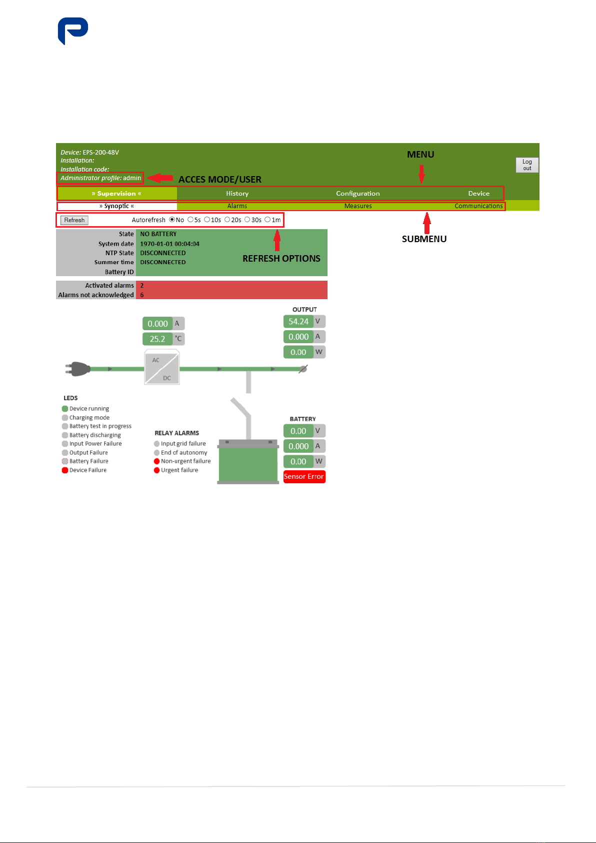
3.1 GENERAL STRUCTURE ................................................................................................ 6
3.2 SITE MAP .............................................................................................................. 7
3.3 AUTHENTICATION..................................................................................................... 7
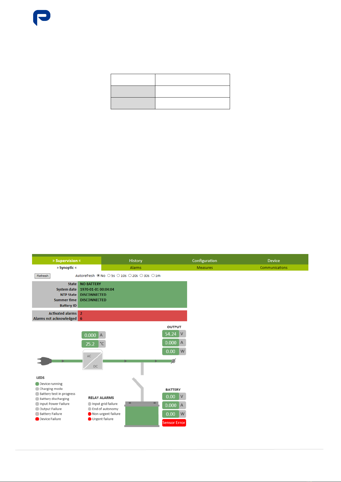
3.4 SUPERVISION ......................................................................................................... 8
3.4.1 Synoptic........................................................................................................ 8
3.4.2 Alarms ........................................................................................................ 10
3.4.3 Measures..................................................................................................... 11
3.4.4 Communications........................................................................................... 12
3.4.5 Device......................................................................................................... 12
3.5 HISTORY ............................................................................................................. 13
3.6 CONFIGURATION.................................................................................................... 18
3.6.1 XML Configuration ........................................................................................ 18
3.6.2 Parameters .................................................................................................. 19
3.6.3 Control........................................................................................................ 22
3.6.4 Network ...................................................................................................... 23
3.6.5 Firmware..................................................................................................... 25
3.7 EXIT .................................................................................................................. 26
3.8 DISCONNECTION DUE TO INACTIVITY ............................................................................ 26
4SNMP V2 ............................................................................................................... 27
5ANNEX .................................................................................................................. 31
5.1 SYNOPTIC SCENARIOS ............................................................................................. 31
5.2 ALARM SCENARIOS................................................................................................. 34
5.3 LOADING DETAILED XML CONFIGURATION FILE ................................................................ 37

EPS Series
Communications' Operation Manual
MA-5192B-1
07-10-2021
3/ 77
www.premiumpsu.com
Powering Your Challenge
1DESCRIPTION OF THE DEVICE
This section describes the most important features of the device in relation to communications.
1.1 INTRODUCTION
The EPS-120-5192 and EPS-200-5193 chargers have WEB services that can be accessed via an
RJ45/Ethernet port.
The device has two microcontrollers: one dedicated exclusively to the charger control and the other one to
the communications control. This fact means that each one has its own firmware.
The diagram shown in Figure 1.1 shows the internal flow of information in the charger.
1.2 PROTOCOLS SUPPORTED
Table 1.1 shows the communications protocols supported and the device functionalities to which they are
related.
Table 1.1 - Protocols
Protocol
Function
TCP/IP
Ethernet/IPv4 Communication
DHCP
Dynamic IP address assignment
ICMP
Ping to equipment
HTTP
WEB access
SNTP
Time synchronization
LDAP
User authentication
SNMP
Searching/modification of device parameters
1.3 PHYSICAL INTERFACE
To perform any of the actions specified in this manual, it will be necessary to have physical access to the
device. The physical interface is a single button, as can be seen in Figure 1.2, labelled "Battery
Reconnection", located near the Ethernet port.
Figure 1.2 - Physical Interface
This interface will be useful for allowing access to the device in local mode. This point is fully specified in
section 0 Local Access.
ETHERNET
CONTROL
CHARGER
CONTROL
COMMUNICATIONS
LEDs
Alarms
FUNCTIONS
CHARGER
Figure 1.1 - Internal information flow diagram

EPS Series
Communications' Operation Manual
MA-5192B-1
07-10-2021
4/ 77
www.premiumpsu.com
Powering Your Challenge
2WEB ACCESS
This section specifies the steps to follow to enable web access to the device.
2.1 ETHERNET CONNECTION
An active Ethernet connection must be available in order for there to be any web access to the device. To
do so, the device must be connected using an Ethernet cat5e cable or higher with an RJ45 connector. At
the other end of the cable, a device will be connected that is configured within the same IP range as the
device.
2.2 WEB CONNECTION
The web access to the device is provided through a PC, using one of the supported browsers specified in
Table 1.2.
Table 1.1 - Supported browsers
Browser Version
Mozilla Firefox 26.0 or higher
Google Chrome 29.0 or higher
Internet Explorer 11.0 or higher
In order to gain access, the IP address of the device must be entered in the address bar. As specified in
Table 1.3, this IP address can be assigned in 3 different ways.
Table 1.2 - IP address assignment methods
Assignment type Value assigned
by default Configurable
Remote
200.0.0.1
YES
DHCP
Disabled
YES
Local
100.0.0.1
NO
2.3 USER TYPE
There are two user types that are associated with the editing modes that the charger allows. These are
defined by accessing the LDAP server. Table 1.4 is an overview of the available modes and allowed functions.
Table 1.3 - Access modes
Mode
Allowed functions
Viewer
View Synoptic, Alarm, Measure, Communications, Device, Parameter and Network values
Search History
Download XML Configuration
Administration
View Synoptic, Alarm, Measure, Communications and Device values
Search History
Download XML Configuration
View and modify Parameter and Network values
Perform control actions
Update Firmware
2.4 LOCAL ACCESS
The device has a method for accessing web services by making a direct (local) connection to it.
This mode allows the same actions to be performed as are allowed when accessing remotely, but with the
following characteristics:
∗No need to have access to an LDAP server to authenticate it
∗Always accessed with the same IP address (100.0.0.1)
∗Username/password relationship is predefined

EPS Series
Communications' Operation Manual
MA-5192B-1
07-10-2021
5/ 77
www.premiumpsu.com
Powering Your Challenge
To access this mode, it is necessary to use a PC and follow the steps below:
1. Check that the device is switched on ("Device ON" LED activated)
2. Press and hold the "Battery Reconnection" button for more than 10 seconds
3. Check that all the LEDs have started blinking
The recommended configuration for the PC is specified in Table 1.5.
Table 1.4 - Recommended PC configuration
Parameter Value
IP 100.0.0.2
Subnet mask 255.255.255.0
Browser See Table 1.2
The maximum time that this mode remains active is 20 minutes, however, it is necessary to exit this mode
once the desired actions have been performed.
In local mode, it will be accessed with the usernames specified in Table 1.6. One of them allows access in
viewer mode and the other in administration mode.
Table 1.5 - Usernames in local mode
Mode
Username
Password
Viewer
search
search
Administration
*
* Request credentials if needed
To exit this mode, it is necessary to follow the steps below:
1. Check that all the LEDs are blinking
2. Press and hold the "Battery Reconnection" button for more than 10 seconds
3. Verify that all LEDs have stopped blinking and are illuminated for normal operation

EPS Series
Communications' Operation Manual
MA-5192B-1
07-10-2021
6/ 77
www.premiumpsu.com
Powering Your Challenge
3WEBSITE
This section describes the different web pages and their functionalities.
3.1 GENERAL STRUCTURE
Figure 2.1 details the different parts that make up a standard website, hosted on the device.
Figure 2.1 - Web page structure

EPS Series
Communications' Operation Manual
MA-5192B-1
07-10-2021
7/ 77
www.premiumpsu.com
Powering Your Challenge
3.2 SITE MAP
Once successfully authenticated, you will have access to the different web pages available for the mode.
Table 2.1 shows the relationship between access modes and accessible web pages.
Table 2.1 - Map of the website
Available in
Menu
Sub-menu
Viewer
Administration
SUPERVISION
Synoptic
Alarms
Measures
Communications
Device
HISTORY
-
CONFIGURATION
XML Configuration
*
Parameters
*
Control
Network
*
Firmware
EXIT
-
* Only the searching of parameters is allowed
3.3 AUTHENTICATION
The first time you connect to an EPS-120-5192 or EPS-200-5193, you will get an authentication window like
the one shown in Figure 2.2.
You must enter the username associated with the mode you want to access, and the correct password.
Figure 2.2 - Authentication
If the username and password entered are valid, a menu like the one in Figure 2.3 will be displayed, in which
you will be able to select the desired and/or allowed access mode.
Figure 2.3 - Authentication menu

EPS Series
Communications' Operation Manual
MA-5192B-1
07-10-2021
8/ 77
www.premiumpsu.com
Powering Your Challenge
The device limits the maximum number of users authenticated at the same time for each mode, as specified
in Table 2.2. If this limit is exceeded, you will be asked if you want to disconnect any of the previously
authenticated users.
Table 2.2 - Authenticated user limit
Mode Maximum number of users
Viewer 4
Administration 1
3.4 SUPERVISION
The following section describes the web pages that can be accessed from the Supervision menu and the
functions that are available on these pages.
3.4.1 SYNOPTIC
The Synoptic page (Figure 2.4) shows the most important information on the current status of the device.
The main element is a schematic representation of the different components that make up the device (AC
Input, Battery and Output) and their interconnection.
The lines connecting the components have 2 states:
∗Green: There is connectivity, and it shows the direction of the electrical current in that section
∗Grey: No power and/or the section has been disconnected
In section 4.1 Synoptic Scenarios of the annex, different screenshots have been added to show the different
states of the connection lines, depending on the status of the device.
The diagram also shows the states of the LEDs as they are on the device itself, and the state of the alarm
relays. Red indicates that the relay is closed.
Figure 2.4 - Synoptic. No battery without temperature probe

EPS Series
Communications' Operation Manual
MA-5192B-1
07-10-2021
9/ 77
www.premiumpsu.com
Powering Your Challenge
This is the page that is accessed after successful authentication on the device.
By default, as will happen with all the pages that have this option, whenever it is accessed, the Autorefresh
option is deactivated (NO option).
HEADER
The header will have the following fields:
•State: Shows the state that the device is in (see Table 2.3)
•System date: This is the date the system is using
•NTP status: Indicates whether or not the device has synchronized the date and time with an NTP
server.
The possible values are ACTIVE / DISCONNECTED.
•Daylight saving: Indicates whether or not the device has the daylight saving time setting activated.
The possible values are ACTIVE / DISCONNECTED.
•Battery identifier: Value configured as battery identifier.
•Alarm activated: Number of active alarms.
•Alarms not acknowledged: Number of alarms not acknowledged by the system.
Table 2.3 - States
Status Description
STARTING The device performs the initial checks before starting up.
QUICK CHARGING Battery charging at constant current.
FLOATING Battery charging in constant voltage mode.
NO BATTERY
There is no battery connected to the device, or the device has disconnected the
battery due to a serious error in the battery.
AC INPUT ERROR The mains voltage is outside the range.
BATTERY TEST A battery test is being carried out in order to check its status in terms of capacity.
OVERLOAD The device has entered overload protection.
OVERLOAD TEST The device is restarting after an overload shutdown.
CHARGER FAILURE
Internal failure of the charger; if it does not recover, it will be necessary to replace the
device.
BATTERY ABSENCE TEST The device is checking if the battery is connected.
BATTERY CHARGED The battery has been floating long enough to be considered charged.
FAILURE TO START At start-up, the device has not reached the minimum voltage within one second.
RECOVERING BATTERY A deeply discharged battery has been connected and the device is trying to recover it.
FORCED OUTPUT SHUTDOWN A temporary disconnection of the output is forced.
LEDS
The possible states of the LED indicators are described in Table 2.4.
If an LED is greyed out, it means that the situation indicated by this LED is not occurring.
Table 2.4 - LEDS
LED
Colour
Mode
Indication
Device ON
Green
Steady light
Charger running
Charging mode Green Steady light Battery charging floating mode
Blinking
Battery charging in constant voltage mode
Battery test in progress
Green
Steady light
Battery test in progress
Battery discharging
Yellow
Steady light
Battery discharging
Mains fault
Red Blinking Mains input voltage outside range
Output failure
Red
Blinking
Output voltage outside range
Battery failure Red
Steady light
Failed battery test, degraded batteries
Blinking
Battery voltage outside range
Equipment failure Red
Steady light
Battery temperature sensor error
Blinking
Internal charger error

EPS Series
Communications' Operation Manual
MA-5192B-1
07-10-2021
10 / 77
www.premiumpsu.com
Powering Your Challenge
ALARM RELAYS
Table 2.5 describes the possible states of the ALARM RELAY indicators.
Table 2.5 - ALARM RELAYS
Alarm relay
Status
Operating logic
Urgent failure Red
Relay closed
- In normal charger operation, this indication is not activated.
- Timed switching off and on (5sec).
- Indication in red if:
- No battery is connected.
- There is a Battery Test Failure.
- The battery is defective or deteriorated.
- There is an urgent internal failure in the rectifier.
- Device temperature outside the range.
End of autonomy Red
Relay closed
- In normal charger operation, the contact is open.
- Timed switching off and on (15sec).
-
Indication in red when the battery is discharging and the voltage
drops to the set minimum value
Mains failure Red
Relay closed
- In normal charger operation, the contact is open.
-Timed switching off and on (5sec).
-
Indication in red if the AC mains voltage is outside the range or
there is no AC.
Non-urgent
failure
Red
Relay closed
-In normal charger operation, the contact is open.
-Timed switching on and off.
- Indication in red if:
- Battery overvoltage is measured.
- There is a temperature probe error.
- Output voltage is outside the range.
- Battery temperature is outside the range.
3.4.2 ALARMS
This page (Figure 2.5) shows the status of the different alarms. The information shown corresponds to the
last time the page was refreshed.
Each alarm can be in two states:
∗Green: The alarm is not activated
∗Red: The alarm is activated
The alarms shown on this page are in turn grouped into 4 blocks. Each of these blocks can be in two different
states:
∗Green: All the alarms in the block are inactive
∗Red: One of the alarms in the block is active
In point 4.2 Alarm Scenarios of the appendix, different examples are shown depending on the active
alarms.
Figure 2.5 - Alarms

EPS Series
Communications' Operation Manual
MA-5192B-1
07-10-2021
11 / 77
www.premiumpsu.com
Powering Your Challenge
3.4.3 MEASURES
This page (Figure 2.6) shows values for the most significant measurements of the device.
The values are grouped into 3 blocks, depending on whether they affect the charger, battery or battery test
parameters. A brief description of all the parameters shown on this page is provided below.
•CHARGER
oState : State that the device is in (see Table 2.3)
oCharger current: Current (A) delivered by the rectifier
oOutput voltage: Voltage (V) at the output of the device
oOutput current: Current (A) at the output of the device
oOutput power: Total power (W) at output
oTemperature: Internal temperature (ºC) of the device
•RECOVERY
oVoltage: Battery voltage (V)
oCurrent: Battery current (A). A negative value indicates that it is discharging
oPower: Power (W) of the battery, both in terms of delivery and charging
oTemperature: Temperature (ºC) measured by the probe
•BATTERY TEST
oTime to Next Battery Test: Remaining time before the next battery test
oBattery discharge capacity: Measured battery capacity (mAh)
oDischarge time: Discharge time (min) measured at last battery test
Figure 2.6 - Measurements
As on the previous pages, there is the option of auto-refreshing the information for the variables shown, at
different time intervals, as well as being able to force it to reload with the Refresh button.
Additionally, a history of the last battery test results is shown, as well as additional information related to
each test.

EPS Series
Communications' Operation Manual
MA-5192B-1
07-10-2021
12 / 77
www.premiumpsu.com
Powering Your Challenge
3.4.4 COMMUNICATIONS
This page (Figure 2.7) shows the values that affect the device's communications. The information shown
corresponds to the last time the page was refreshed.
The only action that can be performed on this page is to refresh the information by clicking the Refresh
button.
Figure 2.7 - Communications
3.4.5 DEVICE
This page (Figure 2.8) shows the status of the device's measurements; the information it displays is from
the last time it was refreshed.

EPS Series
Communications' Operation Manual
MA-5192B-1
07-10-2021
13 / 77
www.premiumpsu.com
Powering Your Challenge
Figure 3.8 - Device
It is very important to note that the COMMUNICATIONS SOFTWARE VERSION field is the one that is
used as a reference to determine the version of the device (2.1 at the time of writing this manual).
The rest of the fields that mention software versions correspond to sub-versions of the main firmware
(Communications Software Version).
3.5 HISTORY
From this page, the events registered by the device can be searched. Figure 2.9 shows the page as it appears
before any searches are performed.
Two actions are allowed from this page:
∗Download all events in a CSV file
∗Filtered search of all events on the website
Data presentation format
The data represented on this website follow the structure of Table 2.6.
Table 3.6 - History input format
N
NTP
DATE
TIME
UNIT
TYPE
DESCRIPTION
ALARM
ACK
1-400
S/C
dd/mm/yyyy
hh:mm:ss.mmm
0-5
1-255
Alarm/event name
YES/NO
YES/NO/Pending
The following is a brief description of each of the fields:
•N: This shall be between 1 and 400. It indicates the input number.
•NTP: The "S" (suspicious) marker for unreliable time will be shown when the NTP server does not
synchronize for at least "si_tfall" time. If the NTP server is synchronized and the time is reliable, the
"C" (correct) marker will be shown.
•DATE: This indicates the date, with two digits for the day, two digits for the month and four digits
for the year, separated by a slash "/".
•TIME: This will consist of two digits for the hour, in 24-hour format, two digits for the minutes and
two digits for the seconds, all separated by a colon ":", and three digits for the thousandths of a
second, separated from the seconds by a dot "."
•GROUP: This is associated with the group classification, as shown in Error! Reference source not
found. and Table 2.8.
•TYPE: This is associated with the type classification, as shown in Error! Reference source not
found. and Table 2.8.
•DESCRIPTION: Displays a specified value according to Error! Reference source not found. and
Table 2.8.
•Alarm: Indicates the activation (YES) or deactivation (NO) status of that event or alarm.
•ACK: Indicates if the alarm has been acknowledged, if it has not generated an alarm that needs to
be acknowledged (NO), if the alarm has been acknowledged (YES), or if it is Pending

EPS Series
Communications' Operation Manual
MA-5192B-1
07-10-2021
14 / 77
www.premiumpsu.com
Powering Your Challenge
Table 3.7 - Recorded events
Classification
Group
Type
Name
Description
Urgent Failure 1
1
Charger failure
Internal device malfunction.
2 High Temp High device temperature.
3 Battery Absent Battery not available.
4
Test failure
Periodic battery test result: failed.
101
Charger OK
Charger is operating correctly
102
Normal charger temperature
Normal device temperature
103
Battery present
Battery available
Non-urgent
failure 2
1
Voutput 1 High
Output voltage outside range: Overvoltage.
2
Voutput 1 Low
Output voltage outside range: Undervoltage.
7
Battery voltage High
Battery voltage outside range: overvoltage
8 Bat Temp High High battery temperature.
9
Temp Bat Low
Low battery temperature.
10 Temp Probe Failure Temperature sensor not detected.
101 Output voltage Normal Main output voltage within the range.
107
Battery voltage normal
Battery voltage within the range
108 Battery temperature normal Battery temperature normal
110 Temperature Probe Normal Temperature sensor normal.
Events 3
1
Vmains Absent
No AC input voltage.
2 Vmains Low AC input voltage outside range: Undervoltage.
3 End of Autonomy Battery empty.
4
Battery connection attempt
Battery connection detected with bat = "0".
101 AC Input Mains Voltage Normal There is AC input voltage.
Other events 4
1
Power UP
Starting the device.
2
Overload
Device in overload.
5 Limitation due to Temp. Power limitation due to high temperature of the device.
6
Quick charging
Battery on quick charge.
7
Discharging
Battery discharging.
8 Floating Battery floating.
9
Battery charged
Battery charged.
10
Battery test
Battery test in progress.
11 Test OK Result of periodic battery test: OK.
12
Forced: Local
Local IP forced from push button.
13
1
Forced: Battery Battery reconnection forced from push button.
14 Forced: Test Battery test forced.
15
Forced: Quick charging
Forced into quick charging.
16 Forced: Floating Forced into floating.
17 Forced: Battery charged Forced into battery charged.
18
Forced: Battery reconnection
Battery absence test forced
19 Forced: Reset Device Force a restart of the device.
20 Forced: Factory parameters Force the loading of default parameters.
21
Forced: AC error relay
Force activation of input mains failure relay.
22 Forced: End of Autonomy Relay Force activation of the end of autonomy relay.
23
Forced: Non-urgent failure relay
Force activation of non-urgent failure relay.
24
Forced: Urgent failure relay
Force activation of urgent failure relay.
25 System alarms acknowledged The system has acknowledged (ACK) all alarms.
26
Daylight saving time activated
It has switched to daylight saving time.
27
Daylight saving time de-activated
It has switched to winter time.
28 Forced: starting from push button Starting the device from the battery using a push button.
29
Forced: Switching main output off
Force switching off of main output for 5s
High
occurrence 5
1
NTP Failure
Failure in connecting to the NTP server.
2 SNMP Failure Failed in sending TRAP SNMP.

EPS Series
Communications' Operation Manual
MA-5192B-1
07-10-2021
15 / 77
www.premiumpsu.com
Powering Your Challenge
Table 3.8 - Manufacturer recorded events
Classification
Group
Type
Name
Description
Manufacturer 0
1
Power up
Starting the power unit
2
Failure to start
Output voltage not reached (<1s)
3
FW updated (COMS)
COMS FW successfully updated
4 FW updated (power) Power FW successfully updated
5
FW update error (COMS)
Error in COMS FW update
6
FW update error (power)
Error in power FW update
7 Watchdog: Communications Automatic restart due to communications failure
8
Watchdog: Charger - battery
Automatic restart due to device failure
9 Gateway communication failure
Internal failure. Communication between gateway and
h
10 Insufficient battery voltage Battery voltage below minimum
11
Defective battery
Battery in poor condition
12 Battery recovery Battery recovery with voltage below minimum
13 Forced: LEDs and relays ON The LEDs and relays have been forced to switch on.
14
Forced: LEDs and relays OFF
The LEDs and relays have been forced to switch off.
17 Forced website: Quick battery test Quick battery test forced (impedance)
18 Battery relay open Battery circuit open for safety
19
AC relay failure
Internal charger failure
20 Battery test run failure Unable to run the battery test
21
Critical disk space
Internal failure. Insufficient disk space
22
Configuration (ext) recovered
Internal failure. External memory file recovered.
23 Configuration (int) recovered Internal failure. Internal flash file recovered.
Figure 3.9 - History home page
Download CSV file
The device allows all the events to be downloaded in a CSV (Comma Separated Values) file that can be
edited directly with a spreadsheet editor. The format of the resulting file can be seen in Figure 2.10.
To download, click on the Export all events in CSV button.
The name of the file that is generated is PSU_log.csv by default.
Figure 3.10 - CSV events file opened in spreadsheet editor

EPS Series
Communications' Operation Manual
MA-5192B-1
07-10-2021
16 / 77
www.premiumpsu.com
Powering Your Challenge
Search on the website
To search the events registered through the website, click on the Search History button.
As you can see in Figure 2.11, on the website, the events are displayed in blocks of a maximum of 10 events
at a time.
Figure 3.11 - History. Search 10 events no filter
Once the table is loaded, arrows can be used to navigate and display more events. The functionality of these
arrows is described in Table 2.9.
Table 3.9 - History. Navigation arrows
Symbol
Function
|<
Move to the start of the event log
<
Go back 10 positions in the event log
>
Go forward 10 positions in the event log
>|
Move to the end of the event log
The relationship between displayed events and the total is also indicated in the box between the navigation
arrows, as described below:
•A: Input number of the first event displayed
•B: Input number of the last event displayed
•T: Total number of events in the log
Search on website with filtering
As part of the website search, it is possible to filter the results to only show the information you are interested
in. To do so, you just need to enter the filtering parameters and click on Search History.
The filtering options allow for filtering based on:
•Group
•Date
A – B [T]

EPS Series
Communications' Operation Manual
MA-5192B-1
07-10-2021
17 / 77
www.premiumpsu.com
Powering Your Challenge
Filter by group
To filter by group, as can be seen in Figure 2.12, select the button with the number of the group you are
interested in searching for. The group number follows that specified in Table 2.7.
The X button is used in order to not select any group, leaving that filter in its default state.
Figure 3.12 - History. Search with group filtering
Filter by date
To filter by date, specify the start date and end date in the format DD/MM/YYYY.
Filtering by date and by group can be combined, as seen in Figure 2.13.
Figure 3.13 - History. Search with date and group filtering
No filter
If you click on the Search History button without specifying any filter parameters, the website will show all
the entries contained in the log as shown in Figure 2.14.

EPS Series
Communications' Operation Manual
MA-5192B-1
07-10-2021
18 / 77
www.premiumpsu.com
Powering Your Challenge
Figure 3.14 - History. Search without filters
3.6 CONFIGURATION
This section describes the web pages that can be accessed from the Configuration menu and the functions
that are available on these pages.
3.6.1 XML CONFIGURATION
The device allows xml files to be loaded in order to modify the configuration according to the specification.
To do so, follow the process described after Figure 2.15.
Figure 3.15 - XML configuration in administration mode
Loading XML file
The process for loading the configuration by this method is as follows:
1. Click on SELECT FILE
2. Select the .XML file containing the configuration that is to be loaded in the device
3. Click on SEND CONFIGURATION
The button will be activated as soon as an accepted file has been selected
4. Click on APPLY CONFIGURATION
The button will be activated if the file that was sent was valid
5. Click on OK in the warning window that opens
6. Depending on the outcome of the process
a. The page will display a message indicating that the configuration has been loaded
b. If the configuration contains an error, this will be indicated and none of the values will be
modified
In chapter 4.3 of the annex, all the messages shown during the process of loading an XML file can be seen.

EPS Series
Communications' Operation Manual
MA-5192B-1
07-10-2021
19 / 77
www.premiumpsu.com
Powering Your Challenge
Download XML file
It also allows an XML file to be downloaded with the parameters that the charger has configured at that
moment. The process for downloading this file is as follows:
1. Click on DOWNLOAD CONFIGURATION
2. Select where you want to save the psu_config.xml file
Viewer Mode
If this page is accessed in viewer mode, as seen in Figure 2.16, the only action that is allowed is to download
the XML configuration file.
Figure 3.16 - XML configuration in viewer mode
3.6.2 PARAMETERS
From this page, the parameters can be modified one by one, manually, if you are authenticated in
administrator mode. The process for making these changes is as follows:
1. Change any fields on the form that you want to change
2. Click on APPLY CHANGES
3. Click on OK in the warning window that opens (see Figure 2.18)
4. Depending on the outcome of the process
a. The page will reload and display the changed values in green (see Figure 2.19)
b. If the configuration contains an error, the field containing the error will be displayed on an
orange background, and none of the values entered will be loaded (see Figure 2.20)
The Apply Changes button is located at the top of the page. Next to each section title, there is a ^symbol
which, when you click it, will scroll the page to the top.
Figure 3.17 - Parameters in administration mode

EPS Series
Communications' Operation Manual
MA-5192B-1
07-10-2021
20 / 77
www.premiumpsu.com
Powering Your Challenge
Figure 3.18 - Warning message
Figure 3.19 - Configuration change with no errors
Figure 3.20 - Configuration change with error
Table 3.10 - EPS-120-5192 parameters
Name
Description
Unit
Increment
Min
Default
Max
AC INPUT
vin_max
Maximum input voltage
V
0.1
90.0
270.0
300.0
vin_min
Minimum input voltage
V
0.1
90.0
180.0
300.0
DC OUTPUT
vo1_nom
Output voltage: Nominal value
V
0.01
30.00
54.96
61.00
vo1_max
Output voltage: Maximum value
V
0.01
50.00
60.00
61.00
vo1_min
Output voltage: Minimum value
V
0.01
30.00
39.00
45.00
RECOVERY
bat
Presence of battery
0:NO / 1:YES
1
0
1
1
tec
Type of technology
Text
-
Pb
-
cap
Battery capacity
Ah
0.01
1.00
2.50
38.00
BATTERY - REGULATION IN CHARGING
ilim
Maximum battery charging current
A
0,001
0,000
0,250
3,000
comp_tmax
Maximum temperature for temperature compensation
ºC
1
0
40
80
comp_tmin
Minimum temperature for temperature compensation
ºC
1
-20
0
80
BATTERY - REGULATION IN FLOATING
v_float
Floating battery charging voltage
V
0.01
50.00
54.96
60.00
comp_float
Temperature compensation in floating
mV/ºC
0.1
0.0
72.0
500.0
tmin_float
Minimum floating time in order to consider battery charged
h
1
1
13
24
BATTERY - QUICK CHARGING
v_charging
Quick charging voltage
V
0.01
48.00
58.80
60.00
comp_charging
Temperature compensation
mV/ºC
0.1
0.0
72.0
500.0
enab_comp
Enable temperature compensation in quick charging
0:NO / 1:YES
1
0
0
1
i_float
Battery current for switching to floating
mA
1
1
15
500
tlim_charging
Maximum time to stay on quick charge
h
1
1
8
24
BATTERY - BATTERY TEST
v_end
Voltage limit for failing the Test
V
0.01
30.00
43.00
50.00
period
Period between each battery test
Weeks
1
1
16
60
cap_dis
Battery test: discharge capacity
Ah
0.01
0.00
1.00
38.00
tlim_test
Battery test: Time limit for each test attempt
h
1
1
24
99
retry
Number of retries
Units
1
0
1
9
BATTERY - ALARMS
tbat_high
Maximum battery temperature
ºC
1
10
50
80
tbat_low
Minimum battery temperature
ºC
1
-20
0
80
BATTERY - DISCONNECTION
disc_v_max
Disconnection voltage: upper limit
V
0.01
50.00
60.00
60.00
disc_v_min
Disconnection voltage: lower limit
V
0.01
30.00
42.00
50.00
disc_imm
Immediate disconnection voltage
V
0.01
30.00
39.00
50.00
Other manuals for EPS-120-5192
2
This manual suits for next models
1
Table of contents
Languages:
Other Premium Power Supply manuals
Popular Power Supply manuals by other brands

GM International
GM International D1014S Instruction & safety manual

B+K precision
B+K precision 9115/B user manual

TYCON Solar
TYCON Solar UPSPro UPS-PL-120 SM quick start guide

B+K precision
B+K precision 1653A instruction manual

Securitytronix
Securitytronix ST-PS12V5A-PTC installation manual

qtran
qtran QTM-eLED+DALI-DT8 Installation