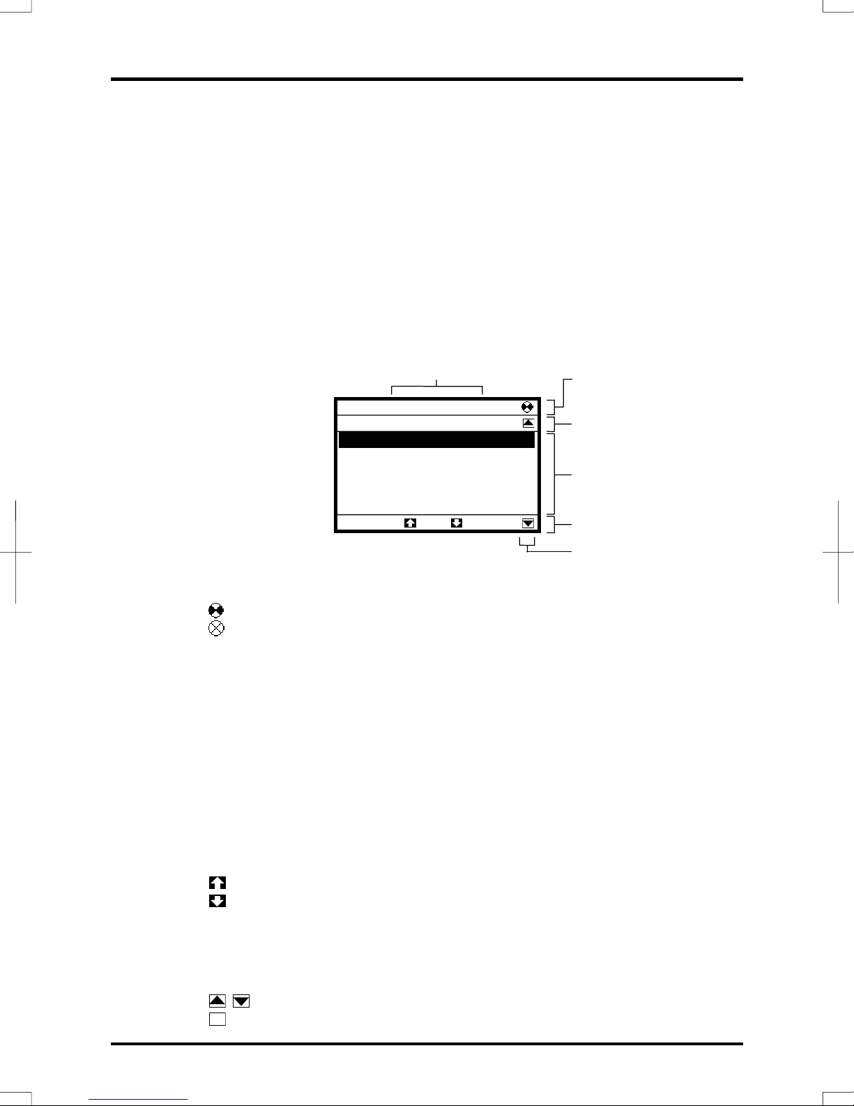
Toshiba RKP004Z-0 User manual

E6581323
LCD Remote Keypad
Instruction Manual
RKP004Z-0
Notice
1. Please see to it that this instruction manual reaches the actual user of the LCD remote
keypad without fail.
2. Be sure to read this instruction manual carefully before installing and using the LCD remote
keypad. After reading the manual, be sure to store it.


Introduction
ⅰ
Thank you for purchasing a LCD remote keypad (RKP004Z-0) designed specifically for
Toshiba VF-AS1 series industrial inverters.
The use of this LCD remote keypad (also referred to as the unit, the product and the
remote keypad) equipped with a high-resolution liquid crystal display with back lighting
makes it easier to set parameters or monitor the operation.
The unit can be mounted easily on an inverter's operation panel, and on a board by
means of an optional attachment. Moreover, using the unit along with a dedicated
interconnect cable makes it possible to operate the inverter by remote control.
The remote keypad supports two languages: Japanese and English.
This instruction manual mainly explains how to use the keys on the LCD remote keypad.
For details of parameters available, refer to the instruction manual included with your
inverter.
Danger
Prohibited
●Never connect the unit to any inverter other than a VF-AS1 series inverter
or any communications device. Do not use any cable other than an
optional interconnect cable designed specifically for the unit.
Failure to observe this might cause the unit to break down and result in an
electric shook or fire.
■Explanation of model code
RKP 004 Z―0
■Check product purchase
Before using the unit, make sure all the following items are packaged with the
product. If any item is missing, please contact our customer support desk.
Product (remote keypad)
(RKP004Z)
Instruction Manual (1)
This manual
Introduction
Revision No.
Cable length (Z: No cable)
Optional LCD keypad
Optional remote keypad

Introduction
ⅱ
■Optional products
The products listed below are optionally available. Purchase these cables and
attachments separately.
Product Model number Product Model number
Interconnect cable
CAB0071
(1m)
Connector
CNT001Z
Interconnect cable
CAB0073
(3m)
IP54 attachment
SBP006Z
Interconnect cable
CAB0075
(5m)
IP65 attachment
SBP007Z
You can install the LCD remote keypad to the inverter or operate the inverter by
remote control combining optional products.
⇒For details, refer to 2. Installing the LCD remote keypad.
«Installation on an inverter (no optional products required)»
RKP-004Z
«Installation on a board»
++
RKP-004Z SBP006Z CAB007□
«Installation on a board (protective structure)»
++ +
RKP-004Z SBP006Z SBP007Z CAB007□
«Remote control»
++
RKP-004Z CNT001Z CAB007□

7. 状態モニタモードでの操作
ⅲ
This section provides important information that the user must always keep in mind
when using the product in order to avoid personal injury and damage to property. Read
these instructions carefully and follow them strictly.
■Limits in purpose
●Be sure to contact your retailer if you wish to use the product with a system, such as a
nuclear facilities control system, aerospace system, transportation system, or safety
system, that could threaten human life or do harm to human body if the inverter breaks
down or malfunction.
●When using the unit with important facilities, provide the facilities with a safety device that
prevents the occurrence of a serious accident, for example, when the inverter fails to put
out a failure signal. (For more information, contact your retailer.)
●Do not use the product for any purposes other than the control of the rotational speed of a
general-purpose industrial three-phase induction motor. (Use under any other conditions
may result in malfunction.)
■General Operation
Danger
Disassem
bly
prohibited
●Never disassemble, modify or repair. This can result in electric shock, fire and
injury. For repairs, call your sales agency.
Prohibited
●Don't place or insert any kind of object into the inverter (electrical wire cuttings,
rods, wires). This can result in electric shock or fire.
●Do not allow water or any other fluid to come in contact with the inverter. This can
result in electric shock or fire.
●Do not use any cable other than a dedicated interconnect cable (optional).
Failure to observe this might result in an electric shock or fire.
Mandatory
●If the inverter begins to emit smoke or an unusual odor, or unusual sounds,
immediately turn power off. If the equipment is continued in operation in such a
state, the result may be fire. Call your local sales agency for repairs.
■Transportation & installation Danger
Prohibited
●Do not place any inflammable objects nearby. If a flame is emitted due to
malfunction, it may result in a fire.
●Do not install in any location where the inverter could come into contact with
water or other fluids. This can result in electric shock or fire.
Mandatory
●Must be used in the environmental conditions prescribed in the instruction
manual. Use under any other conditions may result in malfunction.
Safety precautions

Safety precautions
ⅳ
■Operations Danger
Prohibited
●Do not touch switches when the hands are wet and do not try to clean the
inverter with a damp cloth.
Such practices may result in electric shock.
■Disposal Warning
Mandatory
●If you throw away the inverter, have it done by a specialist in industry waste
disposal*.
If the collection, transport and disposal of industrial waste is done by someone
who is not licensed for that job, it is a punishable violation of the law. (Laws in
regard to cleaning and processing of waste materials)
* Persons who specialize in the processing of waste and known as “industrial
waste product collectors and transporters” or “industrial waste disposal
persons.”
■Notes on use
Notes
●Insert a magnetic contactor or a similar device between the inverter and its
power supply so that the system connected can be stopped without fail using an
external control device in case of an emergency.

ⅴ
1. Names and functions ・・・・・・・・・・・・・・・・・・・・・・・・・・・・・・・・・・・・・・・・・・・・・・ 1-1
2. Installing the LCD remote keypad ・・・・・・・・・・・・・・・・・・・・・・・・・・・・・・・・・・・ 2-1
2. 1 Installing the remote keypad to the inverter ・・・・・・・・・・・・・・・・・・・・・ 2-1
2. 2 Installing the remote keypad to the board (optional)・・・・・・・・・・・・・・ 2-2
2. 3 Remote control (optional)・・・・・・・・・・・・・・・・・・・・・・・・・・・・・・・・・・・・・・ 2-3
3. Setting to be made when turning on the unit for the first time ・・・・・・・・・ 3-1
4. About available modes ・・・・・・・・・・・・・・・・・・・・・・・・・・・・・・・・・・・・・・・・・・・・・ 4-1
5. Operation in Top View Mode ・・・・・・・・・・・・・・・・・・・・・・・・・・・・・・・・・・・・・・・・ 5-1
5. 1 Setting a panel operation frequency ・・・・・・・・・・・・・・・・・・・・・・・・・・・・ 5-1
5. 2 Using an EASY key function ・・・・・・・・・・・・・・・・・・・・・・・・・・・・・・・・・・・ 5-2
5. 3 Selecting a language to be displayed ・・・・・・・・・・・・・・・・・・・・・・・・・・・ 5-3
5. 4 Performing jog run ・・・・・・・・・・・・・・・・・・・・・・・・・・・・・・・・・・・・・・・・・・・・ 5-4
5. 5 Emergency stop/reset operation・・・・・・・・・・・・・・・・・・・・・・・・・・・・・・・・ 5-4
6. Operation in Parameter Setup Mode・・・・・・・・・・・・・・・・・・・・・・・・・・・・・・・・・ 6-1
6. 1 Searching for the change histories of parameters
(History function) ・・・・・・・・・・・・・・・・・・・・・・・・・・・・・・・・・・・・・・・・・・・・・ 6-1
6. 2 Setting a basic parameter・・・・・・・・・・・・・・・・・・・・・・・・・・・・・・・・・・・・・・ 6-2
6. 3 Setting an extended parameter ・・・・・・・・・・・・・・・・・・・・・・・・・・・・・・・・・ 6-3
6. 4 Searching for parameters whose settings were changed
(Search for changed settings) ・・・・・・・・・・・・・・・・・・・・・・・・・・・・・・・・・ 6-4
7. Operation in Status Monitor Mode・・・・・・・・・・・・・・・・・・・・・・・・・・・・・・・・・・・ 7-1
7. 1 Displaying details of an item monitored ・・・・・・・・・・・・・・・・・・・・・・・・・ 7-2
8. Before making a service call・・・・・・・・・・・・・・・・・・・・・・・・・・・・・・・・・・・・・・・・ 8-1
9. Specifications ・・・・・・・・・・・・・・・・・・・・・・・・・・・・・・・・・・・・・・・・・・・・・・・・・・・・・ 9-1
10. Warranty ・・・・・・・・・・・・・・・・・・・・・・・・・・・・・・・・・・・・・・・・・・・・・・・・・・・・・・・・ 10-1
Contents

1. Names and functions
1-1
②
③
④⑤
①
⑨
⑧⑥
⑦
⑩
①LCD panel
For an explanation of windows displayed, see the next page.
②to ⑤[F1] to [F4] function keys
The function of each function key varies depending on the window currently
displayed. For details, see the pages explaining how to operate the unit.
⑥[ESC] key
Each time this key is pressed, modes change from one to another. Also, pressing
this key brings you back to the window one level higher in the window hierarchy.
⑦[FWD/REV] key
Each time this key is pressed, the direction of operation changes between forward
run and reverse run.
(To use this key, parameter settings need to be changed. ⇒Refer to page 1-3.)
⑧[RUN] key
Starts operation.
(To use this key, parameter settings need to be changed. ⇒Refer to page 1-3.)
⑨[STOP/RESET] key
Stops operation.
(To use this key, parameter settings need to be changed. ⇒Refer to page 1-3.)
In case the inverter has tripped, pressing this key twice in a row resets the inverter.
* If multiple commands are entered by pressing the three keys [F2], [F3] and [F4] or
[ESC], [FWD] and [RUN] in rapid succession, a stop command will be issued
instead to stop operation.
⑩Control dial ([ENTER] key) *1
In a menu window, turn the dial clockwise or counterclockwise to select a menu item
(the item selected is highlighted) and press the dial to confirm the menu item
selected.
Turn the dial clockwise (+) to select an item that follows the item currently selected.
Turn the dial counterclockwise (-) to select an item that precedes the item currently
selected.
Selecting a menu item by turning the dial clockwise or counterclockwise and confirm
the item selected by pressing the dial are referred to as “select/confirm an item.”
1. Names and functions

1. Names and functions
1-2
In a value setting window, turn the dial clockwise or counterclockwise to increment
or decrement the value displayed, and press the dial to confirm the value
specified.*2
Turn the dial clockwise (+) to increment the value.
Turn the dial counterclockwise (-) to decrement the value.
Turning the dial clockwise or counterclockwise to increment or decrement the value
displayed and pressing the dial to confirm the value specified are referred to as
“specify/confirm a value.”
*1: When the control dial is pressed, it performs the same function as the [ENTER]
key on the inverter’s main operation panel.
*2: Some settings are executed only by tuning the control dial.
■LCD panel
This section explains the features of windows available, using the top window of
Status Monitor Mode as an example.
①Displays the mode currently selected.
②Displays the operating status of the inverter in a graphical symbol.
(rotating) : In operation
: Operation impossible (While the frequency is set at 0Hz, the
[RUN] key is pressed.)
EOFF (blinking) : Waiting for emergency stop operation
③Displays the title or status of the window.
④Displays settings both in a menu form and numerically, or a list of various kinds of
information.
⑤Displays the function assigned to each function key in an abbreviation or
graphical symbol.
The abbreviations and graphical symbols in the window correspond to the [F1] to
[F4] keys, respectively starting from the left.
Top : In this example, pressing the [F1] key displays the Top View Mode
window.
: In this example, pressing the [F2] key displays the previous window.
: In this example, pressing the [F3] key displays the next window.
Prm : In this example, pressing the [F4] key displays the Parameter Setting
Mode window.
⑥Graphical symbols displayed vary depending on whether there are windows that
precede or follow the current window.
: There are windows that precede and/or follow the current window.
: There is no window that precedes or follows the current window.
②
③
④
⑤
①
Real-time information
To
p
Prm
Rotative direction Fwd
Frequency reference 60.0Hz
Output current 90%
Input voltage 99%
Output voltage 99%
Status Monitor Mode
⑥

1. Names and functions
1-3
■ About the change of parameter settings
By default, the inverter is set with parameters to the mode in which it controls the
operation of the machine via a terminal board. Moreover, the inverter is set so that
the switching between forward run and reverse run cannot be performed using its
operation panel.
To operate the inverter using this unit, parameter settings need to be changed, as
described below.
Parameter CMOd (Command input mode) =1 (Pane/LCD-option)
Parameter FMOd (Frequency input mode 1)=4 (Pane/LCD-option)
Parameter Fr (Panel Fwd/Rvs selection) =2 (Forward (switchable)),
3 (Reverse (switchable))
This change of parameter settings makes it possible to start operation using the
[RUN] key, to stop operation using the [STOP/RESET] key, and to switch between
forward run and reverse run using the [FWD/REV] key.
Furthermore, it allows you to set an operation frequency using the control dial.
⇒Refer to 5. 1 “Setting a panel operation frequency.”

2. Installing the LCD remote keypad
2-1
The LCD remote keypad can be installed on the inverter and on the board (optional).
Using the unit along with a dedicated interconnect cable makes it possible to operate
the inverter by remote control (optional).
2.1 Installing the remote keypad to the inverter
Turn off the inverter, and then follow these steps.
1Remove the serial RS485 port cover
from the inverter’s main operation
panel.
To detach the cover, wrench it open
using a flat-blade screwdriver or any
other flat-tipped tool.
2Mount the remote keypad on the
inverter’s main operation panel.
Insert the connector on the remote
keypad into the RS485 port while
pushing in the lock knobs, and then
release the lock knobs to secure the
remote keypad.
3Make sure the remote keypad is fixed
securely to the inverter.
2. Installing the LCD remote keypad

2. Installing the LCD remote keypad
2-2
2.2 Installing the remote keypad to the board (optional)
The remote keypad can be mounted on a board by means of an IP54 attachment
(optional).
If an IP65 attachment (optional) is used in combination with an IP54 attachment, the
remote keypad can be installed where it may be splashed with water.
Danger
Prohibited
●Never connect the unit to any inverter other than a VF-AS1 series inverter
or any communications device. Do not use any cable other than an
optional interconnect cable designed specifically for the unit.
Failure to observe this might cause the unit to break down and result in an
electric shook or fire.
Turn off the inverter, as shown in the figure below.
115
104 5.55.5 4-Φ3.5
100
114.5
5
Make a hole in the board, as shown in
the figure below.
IP54 attachment
(optional)
Dedicated interconnect cable
(optional) *
* The pin configuration of the dedicated
interconnect cable is different from that of
any other commercially available cable.
Therefore, be sure to use the dedicated
interconnect cable.
Tapping screws (4 pieces)
Used to secure the attachment.
Remote keypad
IP65 attachment (optional)
Used to be attached to the IP54 attachment

2. Installing the LCD remote keypad
2-3
2.2 Remote control (optional)
Connecting the remote keypad to the inverter unit with a dedicated interconnect cable
and a connector (optional) makes it possible to operate the inverter from a distant
point up to 5m from it.
Danger
Prohibited
●Never connect the unit to any inverter other than a VF-AS1 series inverter
or any communications device. Do not use any cable other than an
optional interconnect cable designed specifically for the unit.
Failure to observe this might cause the unit to break down and result in an
electric shook or fire.
Turn off the inverter, as shown in the figure below.
* The pin configuration of the dedicated interconnect
cable is different from that of any other commercially
available cable.
Therefore, be sure to use the dedicated interconnect
cable.
< Remote keypad >
Dedicated interconnect
cable (optional) *
<Inverter unit>
Serial RS485
connector (2-wire)
Connector (optional)

4. 標準モニタモードでの操作
3-1
When the unit is turned on for the first time after purchase, the Language Selection
window shown below appears on the LCD panel. In this window, select the language
you want to display on the screen.
1The Language Selection window appears on
the screen.
This window appears only when the unit is turned
on for the first time after purchase.
2Select/confirm the desired language using
the control dial.
(In this example, English is selected. There is no
need to select/confirm the language.)
3The Startup window is displayed and soon
replaced by the top window of Top View
Mode.
To
p
View Mode
Fwd 0.0Hz STOP
0.0 Hz
Ln
g
Quick ---
Lan
g
ua
g
e selection
English
日本語
インバータ⇒パネル
CONNECTION IN PROGRESS
V1.1 IE01
Lan
g
ua
g
e selection
English
日本語
3. Setting to be made when turning on the unit for the first time

5. 標準モニタモード
4-1
The LCD remote keypad offers the following three modes, just as with the inverter’s
main operation panel.
(1) Top View Mode
When the remote keypad is turned on, it enters this mode first.
The top window displays the operating status.
In this mode, you can set a panel operation frequency, use a function key as the
EASY key, and soon.
⇒Refer to 5. Operation in Top View Mode.
(2) Parameter Setup Mode
This mode allows you to set parameters.
⇒Refer to 6. Parameter Setup Mode.
(3) Status Monitor Mode
This mode allows you to monitor various kinds of statuses and information, such
as the operating status of the inverter and information on the terminal board.
⇒Refer to 7. Operation in Status Monitor Mode.
The figures below show the top windows of these modes.
To change from one mode to another, press the [ESC] key.
*
* When Quick mode is selected
with the EASY key, other
windows are displayed.
Parameter Setup Mode
Parameter Setu
p
Mode
Cate
g
or
y
Selection
To
p
Mon
History function
Basic Parameters
Extended Parameters
Changed Parameters
ESC
ESC
ESC
To
p
View Mode
Fwd 60.0 Hz STOP
0.0 Hz
Ln
g
Quick ---
Top View Mode
Status Monitor Mode
Real-time information
Top P r m
Rotative direction Fwd
Frequency reference 60.0Hz
Output current 0%
Input voltage 99%
Output voltage 0%
Status Monitor Mode
4. About available modes

5. Operation in Top View Mode
5-1
When the remote keypad is turned on, it enters this mode first, which allows you to
monitor the operating status, set an operation frequency, use a function key as the
EASY key, and switch between languages.
When Panel Jog Run is selected, a jog run frequency also can be specified in this
mode.
■Explanation of the top window
• Display of commands executed:
“Fwd” or “Rvs” is displayed to indicate the
direction of rotation.
The operation frequency is displayed in the form
of “□□.□Hz.”
• Display of operating status:
“RUN” is displayed during operation.
“STOP” is displayed during a stop.
“Trip” is displayed in the event of tripping.
• Display of output frequency:
The operation frequency is displayed in the form
of “□□.□Hz.”
• Display of alarm/tripping:
If an error or tripping occurs, an error or trip code is displayed.
• Display of error/tripping message:
If an error or tripping occurs, an error or trip message is displayed.
Functions of function keys
[F1] key: Switches between Quick mode and Standard Setting mode.
[F2] key: Brings you to the Language selection window.
5.1 Setting a panel operation frequency
When Frequency input mode1 (parameter FMOd=4) as a frequency setting mode, an
operation frequency can be set with the remote keypad.
1Press the control dial.
The panel frequency window appears.
The current operation frequency setting is
displayed at the center of the window.
The current output frequency is displayed in the
upper right section of the window.
The minimum allowable frequency (min) and the
maximum allowable frequency (max) are displayed
at the bottom of the window.
Functions of function keys
The functions keys allow you to select the position or decimal place of each figure
(operation frequency) you want to increment or decrement with the control dial.
[F1] key: Selects the position of hundreds.
[F2] key: Selects the position of tens.
[F3] key: Selects the position of ones.
[F4] key: Selects the first decimal place.
Top View Mode
Fwd 60.0 Hz RUN
60.0 Hz
Overheat alarm
Ln
g
Quick ---
Display of commands
executed
Display of
operating status
Display of output frequency
Display of alarm/tripping
Display of error/tripping
message
Basic Parameters
FC
×100×1000 ×10 ×1
Output frequency 0.0Hz
0.0Hz
min=0.0 max=60.0
Panel fre
q
uenc
y
5. Operation in Top View Mode

5. Operation in Top View Mode
5-2
2After selecting the position of a figure you want
to change, specify/confirm another figure with
the control dial.
(In this example, a frequency of 30.0Hz is
specified.)
Functions of function keys
The functions keys allow you to select the position
or decimal place of each figure (operation
frequency) you want to increment or decrement
with the control dial.
[F1] key: Selects the position of hundreds.
[F2] key: Selects the position of tens.
[F3] key: Selects the position of ones.
[F4] key: Selects the first decimal place.
When you confirm the frequency specified, the screen goes back to the top window
of Top View Mode.
■To change the frequency during operation
Press the control dial during operation to display the operation panel operation
frequency menu and turn the control dial to change the setting.
5.2 Using an EASY key function
The [F1] function key can be used as a substitute for the EASY key on the inverter’s
main operation panel. When the name of the function assigned to the [F1] key is
displayed in the lower left corner of the window, the [F1] key can be used as the EASY
key.
Quick : Function of switching between Quick mode and Standard Setting mode
(parameter F750=0)
Panel : Function of switching between Operation Panel and Remote (parameter
F750=2)
Update : Function of updating the Peak/Minimum Hold setting (parameter F750=3)
* The shortcut key function (parameter F750=1) cannot be used. Even if the parameter
is so set, the name of the function is not displayed on the screen.
■Function of switching between Quick mode and Standard Setting mode
<Standard Setting mode selected when power is turned on (parameter PSEL=0)>
(1) When power is turned on, ”Quick” is displayed. (If the [F1] key is not pressed.)
(2) When the unit enters Parameter Setup Mode in this situation, the ordinary top
window of Parameter Setup Mode appears.
(1) If the [F1] key is pressed while “Quick” is displayed, “Quick” is switched from
normal to reverse video “ ”. (If the [F1] key is pressed.)
(2) When the unit enters Parameter Setup Mode in this situation, the Quick mode
window appears instead of the top window of Parameter Setup Mode.
<Quick mode selected when power is turned on (parameter PSEL=1)>
(1) When power is turned on, “ ” is displayed in reverse video. (If the [F1]
key is not pressed.)
(2) When the unit enters Parameter Setup Mode in this situation, the Quick mode
window appears instead of the top window of Parameter Setup Mode.
Quick
Quick
Basic Parameters
FC
×1000 ×10 ×1
Output frequency 0.0Hz
30.0Hz
min=0.0 max=60.0
Panel fre
q
uenc
y
×100

5. Operation in Top View Mode
5-3
(1) If the [F1] key is pressed when “ ” is displayed in reverse video, “Quick”
is switched from reverse to normal video. (If the [F1] key is pressed.)
(2) When the unit enters Parameter Setup Mode in this situation, the ordinary top
window of Parameter Setup Mode appears.
<Always Quick mode (parameter PSEL=2)>
(1) “ ” is displayed in reverse video.
(2) When the unit enters Parameter Setup Mode in this situation, the Quick mode
window appears instead of the top window of Parameter Setup Mode.
* In this situation, the [F1] key is inoperative.
■Operation Panel and Remote
(1) “Panel” is displayed. (If the [F1] key is not pressed.)
(2) In this situation, operation can be performed by remote control by means of the
terminal board.
(1) If the [F1] key is pressed while “Panel” is displayed, “Panel” is switched from
normal to reverse video “ ”. (If the [F1] key is pressed.)
(2) In this situation, operation can be performed using keys on the remote keypad.
There is no need to switch to Panel Operation mode by changing parameter
settings.
* The switching between operation modes cannot be done during operation.
■Peak/Minimum Hold setting
(1) “Update” is displayed. (If the [F1] key is not pressed.)
(2) The instant the [F1] key is pressed in this situation, a measurement for peak
hold/minimum hold starts. When the [F1] key is pressed, “ ” is
displayed in reverse video. (If the [F1] key is pressed.)
5.3 Selecting a language to be displayed
A language to be displayed on the screen can be selected between Japanese and
English.
In this window, the language selected when turning on the remote keypad for the first
time can also be changed to the other language.
1Press the [F2] (Lng) key.
The Language selection window appears on the
screen.
Select/confirm the desired language with the
control dial.
Functions of function keys
[F1] key: Brings you to the Top View Mode
2Select/confirm the desired language with the
control dial.
(In this example, Japanese is selected.)
Functions of function keys
[F1] key: Brings you to the Top View Mode
Quick
Panel
Update
Quick
Lan
g
ua
g
e selection
∨English
日本語
Top
Lan
g
ua
g
e selection
∨English
日本語
To
p

5. Operation in Top View Mode
5-4
5.4 Performing jog run
When Panel Jog Run is selected (parameter F262=1, CMOd=1), “JOG” is displayed in
the lower right corner of the window. When “JOG” is displayed, jog run can be
performed using the [F4] key.
The switching to jog run cannot be performed during operation. When switching to Jog
Run mode, operation has to be stopped temporarily.
1Press the [F4] key to carry out jog run.
The jog run frequency is displayed on the screen.
(In this example, the operation frequency is set at
5.0Hz.)
Operation continues as long as the [F4] key is
pressed, and it stops when the [F4] key is
released.
Functions of function keys
[F1] key: Switches between Quick mode and
Standard Setting mode.
[F2] key: Brings you to the Language selection
window.
[F4] key: Executes a jog run command.
5.5 Emergency stop/reset operation
To make an emergency stop or to reset the inverter, follow these steps. An emergency
stop can be made when operation is performed with the terminal board (parameter
CMOd=0, 2, 3 or 4).
1Press the [STOP/RESET] key, which displays
the blinking code “EOFF” in the upper right
corner of the window.
2Then press the [STOP/RESET] key again.
The Emergency Stop window appears and the
blinking code “E” is displayed.
To
p
View Mode EOFF
Fwd 60.0 Hz RUN
60.0 Hz
Emargency stop?
Ln
g
Quick ---
To
p
View Mode
Fwd 60.0 Hz Tri
p
E
Emargency stop
Ln
g
Quick ---
To
p
View Mode
Fwd 35.0 Hz JOG
5.0 Hz
Ln
g
Quick JOG
“JOG” is
displayed.

5. Operation in Top View Mode
5-5
3Then press the [STOP/RESET] key again.
The Trip window appears and the blinking code
“CLr” is displayed in it.
4Last of all, press the [STOP/RESET] key once
again to reset the inverter.
To
p
View Mode
Fwd 60.0 Hz Tri
p
CLr
Trip reset? (STOP-Key)
Ln
g
Quick ---
Table of contents
Other Toshiba Keypad manuals

Toshiba
Toshiba RKP004Z User manual

Toshiba
Toshiba RKP007Z User manual

Toshiba
Toshiba RKP007Z User manual

Toshiba
Toshiba RKP007Z User manual

Toshiba
Toshiba RKP002Z User manual

Toshiba
Toshiba TOSVERT VF Series User manual

Toshiba
Toshiba RKP004Z User manual

Toshiba
Toshiba Compliant Manager BMS-CM1280TLE User manual

Toshiba
Toshiba RKP007Z User manual