manuals.online logo
Brands
  1. Home
  2. •
  3. Brands
  4. •
  5. Prestige
  6. •
  7. Remote Starter
  8. •
  9. Prestige APS-997LORA User manual

Prestige APS-997LORA User manual

Other Prestige Remote Starter manuals

Prestige APS-55C User manual

Prestige

Prestige APS-55C User manual

Prestige APSRS Installation and operating manual

Prestige

Prestige APSRS Installation and operating manual

Prestige Prestige 128-8210 User manual

Prestige

Prestige Prestige 128-8210 User manual

Prestige Platinum+ APS 685 User manual

Prestige

Prestige Platinum+ APS 685 User manual

Prestige APS622E User manual

Prestige

Prestige APS622E User manual

Prestige APS787Z User manual

Prestige

Prestige APS787Z User manual

Prestige Platinum+ APS 650 RS User manual

Prestige

Prestige Platinum+ APS 650 RS User manual

Prestige APSRS3Z User manual

Prestige

Prestige APSRS3Z User manual

Prestige PE1BZLR User manual

Prestige

Prestige PE1BZLR User manual

Prestige APS57TM Installation and operating manual

Prestige

Prestige APS57TM Installation and operating manual

Prestige Platinum APS-787a User manual

Prestige

Prestige Platinum APS-787a User manual

Prestige Prestige APS-921 User manual

Prestige

Prestige Prestige APS-921 User manual

Prestige Prestige Platinum 128-7405B User manual

Prestige

Prestige Prestige Platinum 128-7405B User manual

Prestige APS57TM User manual

Prestige

Prestige APS57TM User manual

Prestige APS 650 RS User manual

Prestige

Prestige APS 650 RS User manual

Prestige APS997ZLR Installation and operating manual

Prestige

Prestige APS997ZLR Installation and operating manual

Prestige APS-55TWT User manual

Prestige

Prestige APS-55TWT User manual

Prestige Prestige 128-8613 User manual

Prestige

Prestige Prestige 128-8613 User manual

Prestige APS-687E User manual

Prestige

Prestige APS-687E User manual

Prestige APS-620N User manual

Prestige

Prestige APS-620N User manual

Prestige APS-57E User manual

Prestige

Prestige APS-57E User manual

Prestige APS-45C User manual

Prestige

Prestige APS-45C User manual

Prestige APSRS1Z User manual

Prestige

Prestige APSRS1Z User manual

Prestige PE5B User manual

Prestige

Prestige PE5B User manual

Popular Remote Starter manuals by other brands

FamilyTool FMT002JST instruction manual

FamilyTool

FamilyTool FMT002JST instruction manual

PowerJump LMD-021 user manual

PowerJump

PowerJump LMD-021 user manual

AstroStart 803U user manual

AstroStart

AstroStart 803U user manual

Durite 0-649-20 Leaflet

Durite

Durite 0-649-20 Leaflet

Linear ACCESS AK-21 Installation and programming instructions

Linear

Linear ACCESS AK-21 Installation and programming instructions

Soundstream TARANTULA RS.2 installation guide

Soundstream

Soundstream TARANTULA RS.2 installation guide

Jaycar Electronics MB3752 instruction manual

Jaycar Electronics

Jaycar Electronics MB3752 instruction manual

Ultra Start 72 Series owner's manual

Ultra Start

Ultra Start 72 Series owner's manual

ADS FLASHLOGIC FLRSVW1 Product guide

ADS

ADS FLASHLOGIC FLRSVW1 Product guide

Black Widow Security BW RAS 400 installation manual

Black Widow Security

Black Widow Security BW RAS 400 installation manual

Vector Power City DK080706 Owner's manual & warranty

Vector

Vector Power City DK080706 Owner's manual & warranty

Code Alarm CA-535 owner's manual

Code Alarm

Code Alarm CA-535 owner's manual

EINHELL EGS 3600 Directions for use

EINHELL

EINHELL EGS 3600 Directions for use

Schumacher INSTANT POWER IP-75C owner's manual

Schumacher

Schumacher INSTANT POWER IP-75C owner's manual

EINHELL BT-PS 1000 Directions for use

EINHELL

EINHELL BT-PS 1000 Directions for use

Mazda 0000-8F-H28 installation instructions

Mazda

Mazda 0000-8F-H28 installation instructions

DEI 450ESP owner's guide

DEI

DEI 450ESP owner's guide

Directed Electronics AutoCommand 28624TN Owner's installation guide

Directed Electronics

Directed Electronics AutoCommand 28624TN Owner's installation guide

manuals.online logo
manuals.online logoBrands
  • About & Mission
  • Contact us
  • Privacy Policy
  • Terms and Conditions

Copyright 2025 Manuals.Online. All Rights Reserved.

128-9310
1of 30
1
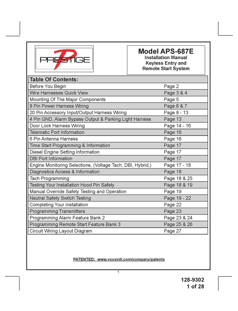
Model APS-997LORA
Installation Manual
2 Way LCD Vehicle Security and
Remote Start System
PATENTED: www.voxxintl.com/company/patents
Table Of Contents:
Before You Begin Page 2
Wire Harnesses Quick View Page 3, 4, & 5
Mounting Of The Major Components Page 6
8 Pin Power Harness Wiring Page 7 - 8
26 Pin Accessory Input/Output Harness Wiring Page 9 - 14
4 Pin GND, Siren & Parking Light Harness Page 15
Door Lock Harness Wiring Page 16 - 18
Telematic Port Information Page 18
6 Pin Antenna Harness Page 18
4 Pin Shock Sensor Harness Page 19
Time Start Programming & Information Page 19
Temperture Start Programming & Information Page 19
DBI Port Information Page 19
Diesel Engine Setting Information Page 19
Diagnostics Access & Information Page 20
Engine Monitoring Selections, (Voltage Tach, DBI, Hybrid,) Page 20
Tach Programming Page 20 & 28
Testing Your Installation Hood Pin Safety Page 21
Manual Override Safety Testing and Operation Page 21
Neutral Safety Switch Testing Page 21 - 23
Dome Delay Learn Circuit Page 24
Shock Sensor Adjusting Page 24
Completing Your Installation Page 25
Programming Transmitters Page 26
Programming Alarm Feature Bank 2 Page 26 & 27
Programming Remote Start Feature Bank 3 Page 28 & 29
Circuit Wiring Layout Page 30
128-9310
2of 30
2
Before You Begin
PROFESSIONAL INSTALLATION IS
STRONGLY RECOMMENDED
Roll down window to avoid locking the keys in the vehicle during
installation
Avoid mounting components or routing wires near hot surfaces
or near moving parts like the steering wheel as it may prevent
proper operation of the vehicle
Tape or loom wires under the hood and dash for protection as
well appearance
Use grommets when routing wires through metal surfaces to prevent
chang and shorting
Use a Digital Multi Meter for testing and verifying circuits. DO
NOT USE A "TEST LIGHT" OR "COMPUTER SAFE PROBE" as
these can set o󰀨 air bags or damage sensitive vehicle computers
and electronics
For technical support go to www.avxtech1.com
or call 1 800 225 6074
FCC COMPLIANCE
This device complies with Part 15 of the FCC rules and with RSS-210 of Industry Canada.
Operation is subject to the following two conditions:
1. This device may not cause harmful interference, and
2. This device must accept any interference received, including any interference that may
cause undesired operation.
Warning!
Changes or modications not expressly approved by the party responsible for
compliance could void the user’s authority to operate the equipment
NOTE:The manufacturer is not responsible for any radio or TV interference caused by unauthorized modications to
this equipment. Such modications could void the user’s authority to operate the equipment
FCC COMPLIANCE
This device complies with part 15 of the FCC Rules. Operation is subject to the following two conditions:
(1) This device may not cause harmful interference, and
(2) this device must accept any interference received, including interference that may cause undesired operation.
This equipment has been tested and found to comply with the limits for a Class B digital device, pursuant to part 15 of the FCC Rules. These limits are designed to provide reasonable protection against harmful interference in
a residential installation. This equipment generates, uses and can radiate radio frequency energy and, if not installed and used in accordance with the instructions, may cause harmful interference to radio communications.
However, there is no guarantee that interference will not occur in a particular installation. If this equipment does cause harmful interference to radio or television reception, which can be determined by turning the equipment off
and on, the user is encouraged to try to correct the interference by one or more of the following measures:
—Reorient or relocate the receiving antenna.
—Increase the separation between the equipment and receiver.
—Connect the equipment into an outlet on a circuit different from that to which the receiver is connected.
—Consult the dealer or an experienced radio/TV technician for help.
Warning!
Changes or modifications not expressly approved by the part responsible for compliance could void the use's authority to operate the equipment
NOTE:The manufacturer is not responsible for any radio or TV interference caused by unauthorized modifications to this
equipment. Such modifications could void the user's authority to operate the equipment.
128-9310
3of 30
3
26 Pin Main Wiring Harness #1124302
1 Green/White Dome Light Output (-)
2 LT. Blue Ground While Running Output (-)
3 Black/White Horn Output (-)
4 Purple (+) Door Trigger input
5 Brown/Black (+) Inhibit/Shutdown To Brake Switch
6 DK. Blue/Black External Remote Start Trigger Input (-)
7 Orange/Black (-) Parking Brake Input
8 Green/Yellow Glow Plug Input
9 Brown (-) Door Trigger Input
10 Green/Orange Tachometer Input
11 DK Green (-) Instant Trigger Input
12 NC No Connection, Empty Cavity
13 LT. Green (-) Trigger Input
14 DK. Blue Channel 3 Trunk Release Output (-)
15 Green/Black Channel 4 Output (-)
16 DK.Blue/Red Channel 7 Output (-)
17 Black/LT.Green Pulse Aer Start Output (-)
18 Black/Blue Pulse Before Start Output (-)
19 Black/Red Pulse Aer Shut Down Output (-)
20 Black/Yellow Pulse During Crank Output (-)
21 LT. Blue/Black Channel 6 Output (-)
22 LT.Blue/Green Channel 5 Output (-)
23 Gray/Black (-) Inhibit/Shutdown To Hood Switch
24 Orange Start Inhibit Relay Control (-)
25 White/Blue (-) Headlight Activation Output
26 Orange/White N.O Start Inhibit Relay Control (-)
128-9310
4of 30
4
8 Pin Power / Start Harness #1124299
3 Pin Door Lock Output Harness #1122906
4 Pin 2nd Main Harness #1124301
4 Pin Shock Sensor Harness #1122591
1
Blue Ignition 1 (+)
2
Red/White Battery 1 - 12V (+)
3
Green Ignition 2 (+)
4
Pink Ignition 3 Common Contact
5
Purple Accessory (+)
6
Red Battery 2 - 12V (+)
7
Yellow Starter Output
8
Red/Black Ignition 3 Normally Open Contact
1 Black Chassis Ground
2 White/Red Parking Light Relay Input
3 White/Black (+) Siren Output
4 White Parking Light Relay Output
1 Red (-) Door Lock Output
2 Green (-) Door Unlock Output
3 Red/Black (-) 2nd Door Unlock Output
1 Blue Predetect
2 Green Full Trigger
3 Black Chassis Ground
4 Red + 12 Volts
128-9310
5of 30
5
6 Pin Antenna Harness #1124293
1 Red + 5 VDC
2 Green RX
3 Black Ground
4 Grey Valet Enable
5 Blue LED Cathode
6 Blue TX
TRX17LORA
1181259
128-9310
6of 30
6
6
This unit is to be used in vehicles with AUTOMATIC TRANSMISSIONS only! Although this combination
Alarm/Remote Start unit is a sophisticated system with many advanced features, IT MUST NOT be in-
stalled into a vehicle with a manually operated transmission. Doing so may result in serious personal
injury and property damage!
INSTALLATION OF THE MAJOR COMPONENTS:
CONTROL MODULE: PART # 1365405
Select a mounting location inside the passenger compartment (up behind the dashboard). The mounting
location selected must be within 24" of the ignition switch wiring harness to allow connection of the 6 pin
main wiring harness. Be certain that the chosen location will not interfere with proper operation of the
vehicle. Avoid mounting the module to or routing the wiring around the steering shaft/column, as the mod-
ule or wiring may wrap around or block the steering wheel preventing proper control of the vehicle. The
module will be secured after all wiring is completed which will allow complete access until the job is done.
Do Not Mount The Module In The Engine Compartment, as it is not waterproof.
SIREN: PART# AS9903E
Select a location in the engine compartment that is not accessible from below the vehicle. The selected
location must be clear of hot or moving parts within the engine compartment The siren must be pointed
downward to prevent water retention and the open or ared end must be pointed away from and out of
the engine compartment for maximum sound distribution. Before securing the siren, check behind your
chosen location to assure that the mounting screws will not penetrate any factory wiring or uid lines.
Secure the siren mounting bracket using #8 self taping screws.
HOOD PIN SWITCH: PART # 1363699
The pin switch included in this package is intended for protecting the hood area of the vehicle. In all cases,
the switch must be mounted to a grounded metal surface. When the pin switch is activated, (hood open),
it will supply a ground to the input wire activating the alarm. In addition, the hood switch is required for
the safety shut down of the remote start unit. If the vehicle is being worked on, this hood switch prevents
the remote start activation even if the RF command to start is issued. This switch must be installed in
all applications. Failure to do so may result in personal injury or property damage.
PUSH-BUTTONPROGRAM SWITCH/LED/RECEIVER/ANTENNA ASSEMBLY: PART # 1181259
The Superheterodyne Receiver Antenna Assembly provided with this unit allows routing from below the
dash board for maximum operating range. Choose a location above the belt line (dashboard) of the vehicle
for best reception. Special considerations must be made for windshield glass as some newer vehicles
utilize a metallic shielded window glass that will inhibit or restrict RF reception. In these vehicles, route
the antenna toward a rear window location for best reception. Secure the antenna with double stick tape
provided.
SHOCK SENSOR: PART # AS9492a
Select a centrally located, solid mounting surface for the shock sensor that will allow consistent operation
from all areas of the vehicle. The selected location must be within 18" of the control module to allow
routing and connecting of the 4 pin harness. Secure the shock sensor to the chosen location using two
#8 self tapping sheet metal screws. The sensor can also be secured to an existing dash brace using
cable tie straps. Whichever mounting method is used be sure to allow access to the sensitivity adjustment
potentiometer for use later in the installation.
STARTER INHIBIT RELAY: PART # 1363731
Select a mounting location within 12" of the ignition switch's low current start solenoid wire. Secure the
relay to an existing harness in the chosen location using a cable tie around the relay's wiring harness.
CAUTION!Do not wire tie the metal bracket to an existing wiring harness as vibration may cause
cha󰀩ng and shorting damaging the factory wiring. If an existing harness is not available then
secure the relay's metal mounting tab to an under dash metal brace with a #8 self tapping
sheet metal screw. Wire the relay as per the diagram found later in this manual.

128-9310
7of 30
7
IMPORTANT!
DO NOT PLUG THE EIGHT PIN MAIN POWER HARNESS OR THE MULTI PIN INPUT / OUTPUT
HARNESS INTO THE CONTROL MODULE UNTILALL CONNECTIONS TO THE VEHICLE HAVE BEEN
MADE. AFTER SELECTING YOUR TARGET WIRES AS DEFINED BELOW, DISCONNECT THE NEG-
ATIVE BATTERY CABLE FROM THE VEHICLE BATTERY PRIOR TO MAKING ANY CONNECTIONS.
Note: Do not remove the fuse holders from this wire harness. Fuses must be used and located
as close as possible to the power source for adequate protection of the vehicle.
WIRING THE 8 PIN MAIN POWER HARNESS: PART # 1124299
Note: Do not remove the fuse holders from this wire harness. Fuses must be
used and located as close as possible to the power source for adequate protec-
tion of the vehicle.
1 BLUE Wire: Ignition 1 Output
Connect this wire to the ignition 1 wire from the ignition switch. This wire will show +12 volts when the
ignition key is turned to the "ON" or "RUN" and the "START" or CRANK" positions, and will have 0 volts
when the key is turned to the "OFF" and "ACCESSORY" positions.
For Diesel Applications, this wire must be connected to the ignition circuit that powers the glow plugs if
the vehicle requires glow plug pre-heating. (See selectable feature Bank 3 #12)
2 RED/WHITE WIRE: + 12 volt Battery 1 Source Fused 30A
Locate the vehicle battery wire(s) at the ignition switch. Verication: These wires will register voltage in all positions
of the ignition switch. Connect the Red w/White wire to the vehicle's battery wire. This wire provides power for the
control circuit as well as the ignition 1 and ignition 2 relays.
3 GREEN Wire: Ignition 2 Output
Connect this wire to the ignition 2 wire from the ignition switch. This wire will show + 12 volts when the
ignition key is turned to the "ON" or "RUN" position and is some cases the "START" or CRANK" position.
This wire will show 0 volts when the key is turned to the "OFF" and "ACCESSORY" positions.
NOTE: See programming information (Bank 3 Selection #7) concerning this wire to allow output during
the "START" mode.
4 PINK Wire: Additional Ignition Output
This wire can be used as an additional + 12 Volt ignition output supplied by the Red/Black wire. This
output can be selected to be on or o󰀨 during the start cycle. (See feature bank 3 selection # 8) Connect
this wire to the third ignition circuit in the vehicle and set the selectable feature # 8 of Bank 3 according
to the way in which the vehicle's ignition switch operates.
5 PURPLE Wire: Accessory Output
Connect this wire to the Accessory wire from the ignition switch. This wire will show + 12 volts when the
ignition switch is turned to the "ACCESSORY" or "ON" and "RUN" positions, and will show 0 volts when
the key is turned to the "OFF" and "START" or "CRANK" positions.
6 RED WIRE: + 12 Volt Battery 2 Source Fused 30A
Locate the vehicle battery wire(s) at the ignition switch. Verication: These wires will register voltage in all positions
of the ignition switch. Connect the Red wire to the vehicle's battery wire. This wire provides power for the start
relay and the accessory relay.
7 YELLOW Wire: Starter Output
Careful consideration for the connection of this wire must be made to prevent the vehicle from
starting while in gear. Understanding the di󰀨erence between a mechanical and an electrical
128-9310
8of 30
8
Start Inhibit Relay
(When Used)
Remote Start Connection
Neutral Safety Switch
Closed In Park & Neutral
Neutral Start Switch will allow you to properly identify the circuit and select the correct installation
method. In addition you will realize why the connection of the safety wire is required for all
mechanical switch congurations.
Failure to make this connection properly can result in personal injury and property damage.
In all installations it is the responsibility of the installing technician to test the remote start unit and ensure
that the vehicle cannot start via RF control in any gear selection other than park or neutral.
In both mechanical and electrical neutral start switch congurations, the connection of the Yellow wire
will be made to the low current start solenoid wire of the ignition switch harness. This wire will have +12
volts when the ignition switch is turned to the start (crank) position only. This wire will have 0 volts in all
other ignition switch positions.
NOTE: This wire must be connected to the vehicle side of the starter cut relay (when used). For the
electrical neutral switch conguration, this connection must be made between the starter inhibit relay,
( when used ) and the neutral safety switch as shown in the following diagram.
Failure to connect this wire to the ignition switch side of the of the neutral safety switch can result in per-
sonal injury and property damage.
SEE NEUTRAL START SAFETY TEST FOR FURTHER DETAILS.
YELLOW START WIRE DETAIL
8 RED/BLACK Wire: + 12 Volts Input
Note: The Red/Black and Pink are dry contacts and may be used for negative switching when necessary.
Connecting the Red/Black to chassis ground will result in Pink being ground when the R/S is activated.
This input is to be connected to a separate, (Other than the wire Red or Red/White is connected to), con-
stant on + 12 volt source which will supply + 12 volt power to the additional ignition output, (Pink), wire.
Connect this wire to a separate + 12 Volt source.
128-9310
9of 30
9
WIRING CONNECTIONS: 26 Pin Accessory Input/Output Harness PART # 1124299
1 Green w/ White trace Wire: Entry Illumination Ground Output
This wire provides a 30 second ground output, (300 mA Max.), whenever the remote is used to disarm
the alarm or to unlock the doors. It also provides a continuous pulsed output whenever the alarm is
triggered. This wire should be connected to an external relay and wired to the vehicles interior entry
lighting circuit whenever the optional Entry Interior Illumination feature is desired.
2 LT. Blue Wire: Ground Output While Running (-) 300mA
This wire provides a 300mA ground output that becomes active 1.5 seconds before the Remote Start
Unit initializes and remains grounded while running plus an additional 2 seconds after the Remote
Start Unit turns o󰀨. In all of the applications described below, a relay will be required.
The Light Blue wire can be used to accommodate the following situations:
A. Sensor By Pass:
If there is a Non Plug in Sensor used with the alarm system and it is not shunted during the Remote
Start activation period, then vibration or noise from the running vehicle can cause the alarm to trigger.
In this case, connect the Light Blue Wire to terminal #86 of a external relay. Connect terminal # 85 of
the relay to a fused + 12 volt battery source. Cut the sensor's trigger wire and connect one end of the
cut wire to terminal #30 and the other end of the cut wire to terminal #87a. Just before the Remote
Start unit is activated, the relay contacts will open, preventing the sensor's operation until the Remote
Start unit shuts o󰀨.
B. Additional Ignition Output:
Some vehicle's may require more than three ignition outputs to start and keep the vehicle's engine
running. If this is the case, connect the Light Blue wire to terminal #86 of an external relay. Connect
terminal # 85 to a fused + 12 volt source. Dependent on the vehicle's requirement, connect terminal
#30, to a fused + 12 volt source, or to ground, and connect terminal 87 to the vehicle to supply the
additional ignition source.
C. GM VATS Key Override:
If the vehicle has the General Motors VATS system installed, you will need to bypass the system while
the vehicle is operating under the control of the Remote Start Unit. To Do This:
1. Measure the resistance of the resistor pellet on the ignition key then select a resistor within 5% of
the key's value
2. Locate the pair of VATS wires in the vehicle, usually a pair of thin gauge wires running from the
ignition switch to the VATS control module.
NOTE: These wires are typically White w/ Black trace and Violet w/ Yellow trace, however in later model
Cadillacs, they are run through an orange sleeve, and are either both Black, both Yellow, or both White
wires. Consult the factory service manual for additional information.
3. Connect the Light Blue Wire from the Remote Start Unit to terminal #86 of an external relay. Con-
nect terminal #85 of the relay to a fused + 12 volt battery source.
4. Cut (#1) wire (as shown), and connect the ignition switch side of the cut wire to terminal #87a of
the relay. Connect the other side of the (#1) wire to terminal #30.
5. Connect the previously selected resistor from terminal #87 to the second (#2) wire (as shown).
NOTE: The above information and following diagram is for the GM VATS system only.
128-9310
10of 30
10
87a 87
30
85
86
To LT Blue, (GWR) Wire
From Multi Pin Harness
To Fused + 12 Volt Battery Source VATS Control Module
VAT Wire #1
VAT Wire #2 Cut Factory Wire
and route through
relay as shown
X
Matching
Resistor
D. Anti-Grind Starter Circuit Connection:
This wire, when connected to a starter inhibit relay, as shown in the diagram below, will prevent the
customer from engaging the starter while the vehicle is running under control of the remote start.
The "E" series Alarm/Start units have the Anti-Grind feature built into the module controlled by the
Orange Start Inhibit Output,,,the keyless start units do not and, if desired, will require this circuit.
30
87a 8586
87
BlackBlack/White
Existing Low Current
Start Solenoid Wire
From Ignition Switch
Start Terminal
To Starter Motor
X
Cut
4002 Diode
4002 Diode
To Orange Wire
Of Alarm/Remote Start
To LT. Blue Gnd While
Running Wire of Remote Start
To + 12 Volt Ignition / Start
3 Black w/ White trace Wire: 300 mA Horn Output
The black w/ white trace wire is provided to beep the vehicle’s horn. This is a transistorized low current
output, and should only be connected to the low current ground output from the vehicle’s horn switch.
If the vehicle uses a + 12 VDC horn switch, then connect the black w/ white trace wire
to terminal 86 of a 30Amp automotive relay, and connect relay terminal 85 to a fused
+ 12 VDC battery source. Connect relay terminal 87 to the vehicle’s horn switch output, and connect relay
terminal 30 to a fused + 12 VDC battery source.
4 Purple Wire: (+) Door Trigger Input
If the vehicle's door courtesy light switches + 12 volts when the door is opened, (Some Fords and some
Imports), you must connect this wire to the positive output from one of the vehicle's door pin switches. In
most cases, the Purple wire will need to be connected to only one door switch no matter how many doors
the vehicle has as most door lighting circuits are wired in parallel. This wire will be shunted when remote
starting the vehicle and will remain shunted, if active, while running under command of the remote start.
If this wire is active when the system is armed, the siren will emit three chirps. When the zone clears, the
siren will emit 1 chirp to conrm full arming.
Note: for vehicles with interior delay lighting see programming under title "Completing The Installation"
5 Brown w/ Black trace Wire: Positive Inhibit Input Plus Trigger When Armed
The Brown w/ Black Trace wire provides an instant shutdown for the Remote Start Control module whenever
it gets + 12 volts also triggers the alarm when armed. If the Brake lights switch in the vehicle switches +