Presto Lifts ECOA PDL60-50 User manual

February 22, 2021
Model:
Serial Number:
Date placed in
service:
PDL Owner’s Manual
PDL60-50, PDL60-60, PDL60-80
Presto Lifts Inc.
50 Commerce Way, Norton, MA 02766
Phone: 800.343.9322
Fax: 888.788.6496
www.PrestoLifts.com
Email: serv[email protected]

2
Presto Lifts PDL Manual
Contents
1 Introduction.................................................................................................................................... 4
1.1 General Specications for Standard Lifts .......................................................................... 4
1.2 Responsibilities of Owner and Users.................................................................................. 4
1.3 Responsibilities of Operators.............................................................................................. 5
2 Safety.............................................................................................................................................. 7
2.1 Safety Alert Symbols ............................................................................................................ 7
2.2 Signal Words ......................................................................................................................... 7
3 Labeling.......................................................................................................................................... 8
3.1 Label Location Diagram ....................................................................................................... 8
4 Installation...................................................................................................................................... 9
4.1 External Power Unit .............................................................................................................. 9
4.2 Pit Installation........................................................................................................................ 9
4.3 Typical Pit Plan.................................................................................................................... 10
4.4 Recommended Pad Plan .....................................................................................................11
4.5 Alternative Pad Plan ........................................................................................................... 12
4.6 General Installation............................................................................................................. 13
4.7 Testing.................................................................................................................................. 16
5 Operation...................................................................................................................................... 17
5.1 Loading ................................................................................................................................ 17
6 Maintenance & Repair................................................................................................................. 18
6.1 Maintenance Devices.......................................................................................................... 19
6.2 Periodic Maintenance ......................................................................................................... 21
6.2.1 Weekly Maintenance................................................................................................... 21
6.2.2 Monthly Maintenance ................................................................................................. 21
6.2.3 Six Months................................................................................................................... 21
6.3 Adjusting Vertical Travel Limit Devices ............................................................................ 22
6.3.1 Mechanical Limit Switches ........................................................................................ 22
6.3.2 Proximity Switches..................................................................................................... 23

3
Presto Lifts PDL Manual
This label (Part No. 10095524) is required by California law.
For more information visit: www.P65Warnings.ca.gov
This lift is design and manufactured in accordance with
ANSI standard MH29.1 – “The Safety Requirements for
Industrial Scissors Lifts”.
7 Troubleshooting .......................................................................................................................... 24
8 Electrical Information.................................................................................................................. 26
8.1 Wiring Schematic................................................................................................................ 26
8.2 Control Panel....................................................................................................................... 27
9 Hydraulic Information ................................................................................................................. 28
9.1 Hydraulic Fluid Specications........................................................................................... 28
9.2 Hydraulic Schematic........................................................................................................... 28
9.3 Hydraulic Power Unit.......................................................................................................... 28
9.4 Hose Specications............................................................................................................ 28
9.5 Hydraulic Arrangements .................................................................................................... 29
9.5.1 Standard Hydraulic Arrangement ............................................................................. 29
9.5.2 Alternative Hydraulic Arrangement .......................................................................... 29
10 Warranty & Contact Information .............................................................................................. 30

4
Presto Lifts PDL Manual
1. Introduction
1.1 General Specications for Standard Lifts
1.2 Responsibilities of Owner and Users
Basic Principles - Owners/users shall apply sound principles of safety, training, inspection,
maintenance, and expected operating environment. It shall be the responsibility of the owner/user
to advise the manufacturer where deection may be critical to the application.
Manuals - Owners/users shall keep and maintain a copy of the operating and maintenance
manual(s) and ensure its availability to operating and maintenance personnel.
Inspection and Maintenance - It shall be the responsibility of the users to inspect and maintain
the industrial scissors lift as required to ensure proper operation. The frequency of inspection
and maintenance shall be based upon the manufacturer’s recommendations and be compatible
with operating conditions and the severity of the operating environment. Machinery that is not in
proper operating condition shall be immediately removed from service until repaired. Maintenance
and repairs shall be made by a qualied person and the repairs shall be in conformance with the
manufacturer’s recommendations.
Maintenance Safety Precautions - Before adjustments and repairs are started on the machine,
the following precautions shall be taken as applicable:
1. Remove the load from the load enclosure.
2. Lower the platform to the full down position.
3. Relieve system pressure from all circuits before loosening or removing any components.
4. All controls in the “o’ position and all operating features secured from inadvertent motion
by brakes, blocks, or other means.
5. Disconnect power and follow established owner/user lockout/tag out policies.
6. Follow precautions and directions as specied by the manufacturer.
Replacement Parts - When parts or components are replaced, they shall be replaced with parts
or components approved by the original manufacturer.
Maintenance Training - The user shall ensure only qualied personnel inspect and maintain the
machine in accordance with the manufacturers recommendations.
Operator Training - An owner/user, who directs or authorizes an individual to operate the
machine shall ensure that the individual has been:
1. Trained in accordance with the manufacturer’s operating manual.
2. Made aware of the responsibilities of operators as outlined in section 1.4 of this manual.
3. Retrained, if necessary, based on the owners/user’s observation and evaluation of the
operator.
Model Lift Capacity Rise Time Approx. Weight
PDL60-50 5,000 Lb. 27 sec.
Up to 4000 Lb.DDL60-60 6,000 Lb. 27 sec.
PDL60-80 8,000 Lb. 42 sec.
Roll-Over Capacity
(fully lowered)
Vertical
Travel
Low
Height
Throw-Over
Plate
Standard
Platform
Maximum
Platform Motor
10,000 Lb. 59” 8” 18” x 60” 6’ x 8’ 8’ x 10’ 3.2 HP

5
Presto Lifts PDL Manual
Modications and additions shall not be performed without the manufacturer’s prior written
approval. Where such authorization is granted, capacity, operation, and maintenance instruction
plates, tags, or decals shall be changed accordingly.
1.3 Responsibilities of Operators
Basic Principles - Operators shall apply sound principles of safety and good judgment in
the application and operation of the machine with consideration given to its intended use
and expected operating environment. Since the operator is in direct control of the machine,
conformance with good safety practices is the responsibility of the operator. The operator shall
make decisions on the use and operation with due consideration for the fact that his or her own
safety as well as the safety of other personnel on or near the machine is dependent on those
decisions.
1. General Training - Only personnel who have received general instructions regarding the
inspection, application and operation of machine, including recognition and avoidance of
hazards associated with their operation, shall operate the machine. Such topics covered
shall include, but not necessarily be limited to, the following issues and requirements:
2. A pre-start inspection
3. Responsibilities associated with problems or malfunctions aecting the operation of the
machine.
4. Factors aecting stability
5. The purpose of placards and decals
6. Workplace inspection
7. Safety rules and regulations
8. Authorization to operate
9. Operator warnings and instructions
10.Actual operation of the machine. Under the direction of a qualied person, the trainee shall
operate the machine for a sucient period of time to demonstrate prociency in actual
operation of the machine.
Pre-start Inspection - Before use each day or at the beginning of each shift, the machine shall
be given a visual inspection and functional test including but not limited to the following:
1. Operating and emergency controls
2. Safety devices
3. Hydraulic system leaks
4. Electrical cables and wiring harness
5. Loose or missing parts
6. Nameplates, precautionary and instructional markings and/or labeling
7. Guarding system (If applicable)
8. Items specied by the manufacturer
Problem or Malfunctions - Any problems or malfunctions that aect the safety of operations shall
be repaired prior to the use of the machine.

6
Presto Lifts PDL Manual
Before Operations - The operator shall:
1. Read and understand the manufacturer’s operating instruction(s) and user’s safety rules or
have them explained
2. Understand all labels, warnings, and instructions displayed on the machine or have them
explained.
Workplace Inspections - Before the machine is used and during use, the operator shall check
the area in which the machine is to be used for possible hazards such as, but not limited to:
1. Bumps, oor obstructions and uneven surfaces
2. Overhead obstructions and electrical hazards
3. Presence of unauthorized persons
4. Other possible unsafe conditions as noted in the operating manual.
Operator Warnings and Instructions - The operator shall ensure the operation of the machine
is in compliance with the following:
Guarding system - Guarding shall be installed and positioned, and access gates or openings
shall be secured per the manufacturer’s instructions.
Distribution of load - The load and its distribution on the platform shall be in accordance with the
manufacturer’s rated capacity for that specic conguration.
Maintaining overhead clearance - The operator shall ensure that adequate clearance is
maintained from overhead obstructions and energized electrical conductors and parts.
Point of Operation - The operator shall not place any part of their body under the platform.
Precaution for moving equipment - When other moving equipment or vehicles are present,
special precautions shall be taken to comply with the safety standards established for the
workplace.
Reporting problems or malfunctions - The operator shall immediately report to a supervisor
any problem(s) or malfunction(s) that become evident during operation. The operator shall ensure
all problems and malfunctions that aect the safety of operations are repaired prior to continued
use.
Capacity limitation - Rated capacity shall not be exceeded when loads are transferred to the
load enclosure.
Work area - The operator shall ensure the area surrounding the machine is clear of personnel
and equipment before lowering the load enclosure.
Securing the machine - The operator shall comply with the means and procedures provided to
protect against use by an unauthorized person(s).
Altering safety devices - Safety devices shall not be altered or disabled.
Modications or alterations of the machine or the fabrication and attaching of frameworks or the
mounting of attachments to the machine or the guarding system shall only be accomplished with
prior written permission of the manufacturer.
Assistance to the operator - If an operator encounters any suspected malfunction or any hazard
or potentially unsafe condition relating to capacity, intended use or safe operation the operator
shall cease operation of the machine and request further instruction from the owner/user.
Problems or malfunctions - Any problem(s) or malfunction(s) that aect the safety of operations
shall be repaired prior to the use of the machine.

7
Presto Lifts PDL Manual
2. Safety
All personnel installing, operating, and maintaining this machine shall read and understand this
manual. For questions or concerns contact the manufacturer.
This machine shall be installed, operated, and maintained by trained and/or qualied personnel
only.
2.1 Safety Alert Symbols
A symbol that indicates a hazard. It is composed of an equilateral triangle surrounding an
exclamation mark. The safety alert symbol is only used on hazard alerting signs. It is not used on
safety notice and safety instructions signs.
A – For use with DANGER signal word; (safety white triangle, safety red exclamation mark, safety
red background)
B – For use with WARNING signal word; (safety black triangle, safety orange exclamation mark)
C – For use with CAUTION signal word; (safety black triangle, safety yellow exclamation mark)
D – For use with DANGER, WARNING, or CAUTION signal words; (safety yellow triangle with a
safety black border and safety black exclamation mark
2.2 Signal Words
Indicates a hazardous situation that, if not avoided, will result in death
or serious injury.
Indicates a hazardous situation that, if not avoided, could result in
death or serious injury.
Indicates a hazardous situation that, if not avoided, could result in
minor or moderate injury.
Indicates information considered important, but not hazard-related
(e.g., messages relating to property damage).
ABCD

8
Presto Lifts PDL Manual
3. Labeling
This machine has labeling to indicate potential hazards this machine may pose when operating
and/or maintaining the machine. All labels must be legible. If any label is missing, damaged, or
otherwise illegible contact the manufacturer for replacement labels.
3.1 Label Location Diagram
LD 1.67x7.00 PRESTO ALPHA C180N

9
Presto Lifts PDL Manual
4. Installation
Installation of this machine shall be performed by trained and/ or qualied personnel
only. The owner/ installer is responsible obtaining any necessary permissions and/ or
permits. Follow all applicable codes and ordinances. Read and understand all safety and
installation information in this manual.
Before installation, remove all shipping materials and verify all components on the packing
list were received. Inspect the machine, all components, wiring and electrical connections,
hydraulic hoses and ttings for damage. If components are missing or damage is found contact
the manufacturer before continuing installation. If not being installed in a pit see Typical and
Alternative Pad Plan sections
To avoid death or serious injury:
• Pinch points and Crush Hazards exist when moving and transporting the machine. Do
not enter under any equipment while moving or transport. Keep hands, feet, and loose
clothing away from moving equipment.
• This machine must be installed on a solid, stable, level surface or machine will be
unstable and can lead to injury. Do not install on asphalt or other unstable surface.
• Never enter beneath the platform unless the machine is unloaded and secured against
lowering using the maintenance device. See section 6.1 Maintenance Devices.
Use appropriate lifting device to lift the machine. Use a load spreader
to lift the machine. Lift the machine using the provided lifting eye-bolts
only. Do not lift the machine by the platform.
This machine must be properly secured to the oor/ ground before
operation or the machine may be damaged.
High Voltage: Electrical service and installation must be performed by
trained and/ or qualied personnel. Lock-out/ tag-out the power source
before installation.
Electric motors create sparks. Do not install the power unit in an area
where ammable gases may be present.
All electrical components and the hydraulic power unit must be
protected from wet and/or dirty environments unless specically
congured for such environments.
4.1 External Power Unit
External power units should be placed within thirty feet (hose length) of the machine to avoid
excess pressure drops. External power units must be protected from moisture and weather.
4.2 Pit Installation
Do not install this machine in a pit unless the machine has been
designed for such installation. Shear points exist and can cause severe
injury. Platforms traveling below oor level may require guarding in
accordance with ANSI MH 29.1. Guarding must be installed before
operation.
1. Verify that the pit dimensions match the pit plan.
2. Verify that pit is clear of tools and other debris before lowering the machine into the pit.
3. Follow General Installation instructions to complete the installation.
10
Presto Lifts PDL Manual
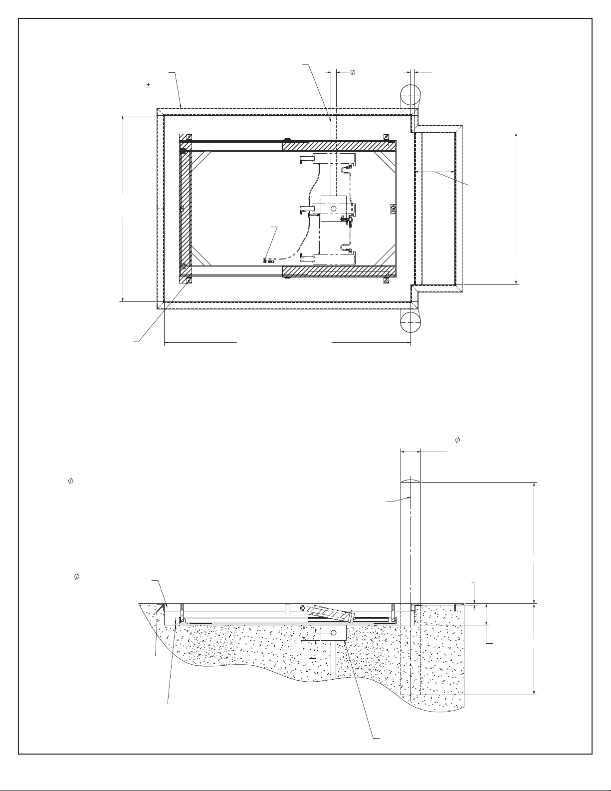
4.3 Typical Pit Plan
FROM ANY DIRECTION
INCLUDING ENTRY FROM
BOTTOM OF PIT SUMP.STEP REQUIRED FOR BRIDGE
PLATE HINGE CLEARANCE
MUST BE SQUARE ( 1/2")
ACROSS CORNERS.
3" X 3" X 1/4" ANGLE BY
PIT CONTRACTOR. ALL
CORNERS TO BE
SECURELY WELDED. PIT
CONDUIT ENTRY CAN BE
COUPLINGS FOR
HYDRAULIC
CONNECTIONS
1 1/2"
BRIDGE
+1-1/2"
PLATFORM LENGTH + 1-1/2"
WIDTH
LENGTH + 1/2"
BRIDGE PLATE
PLATFORM
PLATE
WIDTH
+1/2"
2" CONDUIT
VODIS
COMPACTED WITH NO
ANGLES MUST BE WELL
CONCRETE BEHIND CURB
FRONT OF PIT
ALIGNED WITH
CONCRETE ANCHORS TO
BOLLARDS TO BE
CENTER LINE OF
FROM EACH END.
12" O.C. WITH ONE 3"
1/2" X 6" LOCATED
PREVENT STANDING WATER
PIT DRAIN AS REQUIRED TO
BE
IN PIT. (BY CONTRACTOR)
CROSS HATCHING INDICATES AREAS OF
•
BASE FROM THE MUST BE SHIMMED AND
OR GROUTED AFTER LEVELING OF THE
BASE FRAME TO ENSURE PROPER BASE
FRAME SUPPORT.
CONDUIT RUN IS REQUIRED FOR ROUTING
•
OF HYDRAULIC HOSES AND ELECTRICAL
WIRING UNLESS ALTERNATIVE
ARRANGEMENTS ARE REQUESTED.
2" ELECTRICAL CONDUIT USED WHEN 1/2"
•
HYDRAULIC HOSE, VENT LINE, AND
ELECTRICAL LEADS ARE TO BE INSTALLED
FROM POWER UNIT TO LIFT (BY PIT
CONTRACTOR).
8" BOLLARDS
36"
STEEL PIPE FILLED
48"
1/2"
3"
6" +1/2"
HEIGHT
LOW
(BY CONTRACTOR)
WITH CONCRETE
1/2" SHIM
UNDER EACH
LAG PLATE FOR
PROPER DRAINAGE
Ø3/4” LAG HOLES FOR
Ø5/8” ANCHORS WITH
MIN. 2000 LB PULL
OUT. (BY INSTALLER)
11
Presto Lifts PDL Manual
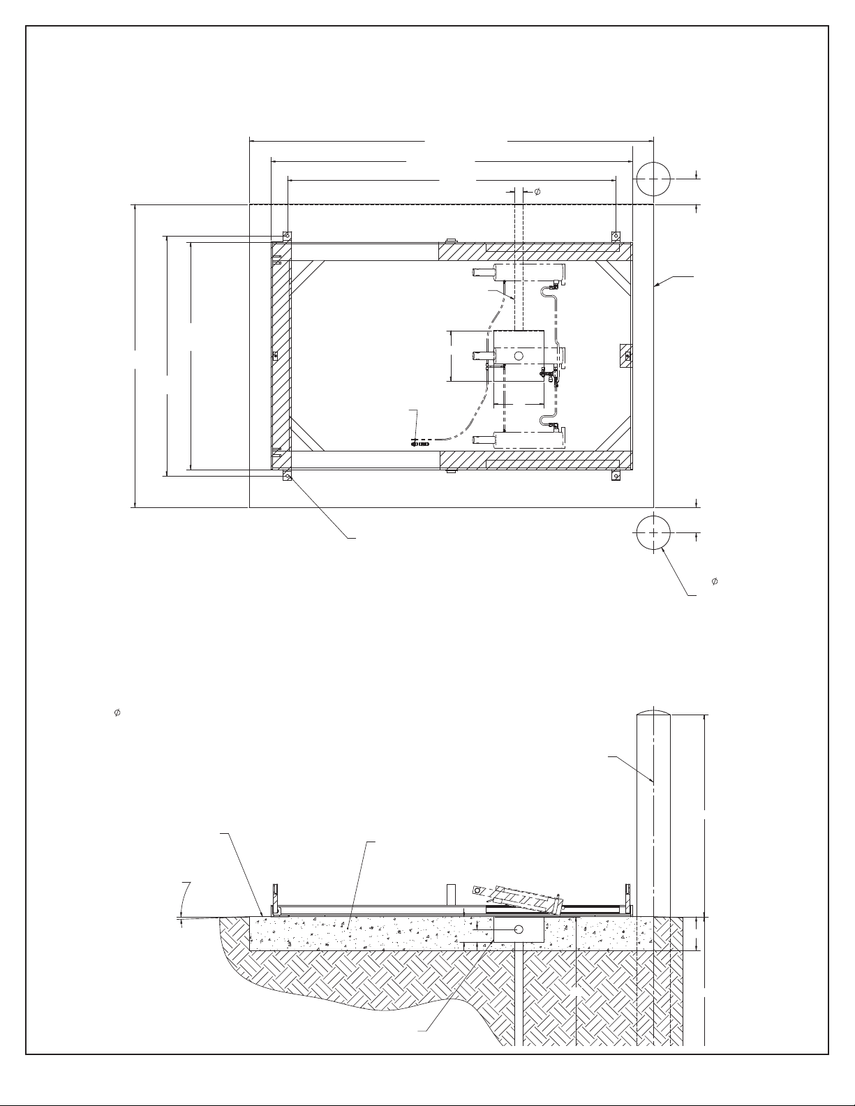
4.4 Recommended Pad Plan
Use of a sump/drain for proper drainage and a conduit run for hydraulic/ electrical routing
in pad is recommended. If no sump/drain and conduit run is provided see Alternative Pad
Plan .
BASE FRAME
2° SLOPE GRADE
AWAY FROM PAD
THROW OVER
PLATE AREA
CONDUIT ROUTE CAN BE
FROM ANY DIRECTION
INCLUDING FROM BOTTOM
OF PIT SUMP
2" CONDUIT
FRAME
BASE
12"
8" STEEL
PIPE
FILLED WITH
CONCRETE TYP.
(BY CONTRACTOR)
PLATFORM
WIDTH
LAGS
LAGS
6"
12"
6"
2X
PLATFORM LENGTH
NOTES:
CROSS HATCHING INDICATES AREAS OF•
BASE FRAME THAT MUST BE SHIMMED
AND/OR GROUTED AFTER LEVELING OF THE
BASE FRAME TO ENSURE PROPER BASE
FRAME SUPPORT.
CONDUIT RUN IS RECOMMENDED FOR•
ROUTING OF HYDRAULIC HOSES AND
ELECTRICAL WIRING.
2" ELECTRICAL CONDUIT USED WHEN 1/2"•
HYDRAULIC HOSE, VENT LINE, AND
ELECTRICAL LEADS ARE TO BE INSTALLED
FROM POWER UNIT TO LIFT (BY
CONTRACTOR).
COUPLINGS FOR
HYDRAULIC
CONNECTIONS
HINGE END OF BASE
NO VOIDS
WELL COMPACTED WITH
SMOOTH AND LEVEL
SURFACE MUST BE
POSTS TO BE ALIGNED WITH
EDGE OF PAD
CENTER LINE OF BUMPER
CONCRETE PAD MUST BE
PAD DRAIN AS REQUIRED TO
PREVENT STANDING WATER
ON PAD (BY CONTRACTOR)
8"
36"
48"
36"
3"
6"
ROLLER END
CONCRETE PAD
Ø3/4” LAG HOLES FOR
Ø5/8” ANCHORS WITH MIN.
2000 LB PULL OUT.
(BY INSTALLER)

12
Presto Lifts PDL Manual
4.5 Alternative Pad Plan
If sump/drain is not used lift will require 1/2” shims under the lag plates to allow proper
water drainage. The base frame must be shimmed and/or grouted according to the pad
plan to ensure the base frame is properly supported. Hydraulic connections are to be
made at the couplings on the roller end of the base frame.
BASE FRAME
2° SLOPE GRADE
AWAY FROM PAD
PLATE AREA
THROW OVER
COUPLINGS FOR
HYDRAULIC
CONNECTIONS. FOR
MACHINES MOUNTED
ON
PADS WITH NO CONDUIT
ROUTING PROVIDED.
6"
LAGS
FILLED WITH
CONCRETE TYP.
(BY CONTRACTOR)
8" STEEL PIPE
PLATFORM LENGTH
PLATFORM
WIDTH
FRAME
LAGS
2X
BASE
6"
NOTES:
IF SUMP IS NOT USED, THE BASE FRAME•
MUST BE RAISED 1/2" TO ALLOW FOR
PROPER WATER DRAINAGE.
CROSS HATCHING INDICATES AREAS OF•
BASE FRAME THAT MUST BE SHIMMED
AND/OR GROUTED AFTER LEVELING OF THE
BASE FRAME TO ENSURE PROPER BASE
FRAME SUPPORT.
IF CONDUIT RUN IN PAD IS NOT USED FOR•
HYDRAULIC ROUTING CONNECTIONS ARE
TO BE MADE AT COUPLINGS ON ROLLER
END OF BASE FRAME.
HINGE END OF BASE
SURFACE MUST BE
SMOOTH AND LEVEL WELL COMPACTED WITH
NO VOIDS
CONCRETE PAD MUST BE
CENTER LINE OF BUMPER
POSTS TO BE ALIGNED WITH
EDGE OF PAD
36"
48"
8"
ROLLER END
Ø3/4” LAG HOLES FOR Ø5/8”
ANCHORS WITH MIN. 2000 LB
PULL OUT. (BY INSTALLER)

13
Presto Lifts PDL Manual
4.6 General Installation
1. Attach a chain or lifting strap, with an appropriate load spreader, to the main lifting eyes.
The chain or strap must pull on the lifting eyes vertically.
2. Using an appropriate lifting device, carefully move the machine into position. Lifting device
must be capable of supporting up to 4000 Lb.
If the hydraulic connectors are accessible, connections can be can be
made and the lift can be powered open using the hydraulic power unit
(HPU). See section 9. Hydraulic Information. Skip instructions three and
four.
Ensure eye bolts have been removed completely before attempting to
raise the platform when using the HPU.
3. Remove the lifting eyes and install them into the second set of holes. The second set of
holes have a nut welded to the bottom of the platform and are used to manually raise the
platform for access during installation. Reattach the chain or strap.
Lifting eyes must be hand tightened only. Over torquing the lifting eyes
may cause the them to fail.
Eye bolts must be removed from holes securing the platform to the base
frame (holes along platform center line) before attempting to raise the
platform.
4. Using the eyes bolts, raise the platform and engage the maintenance device. See the
Maintenance Devices section. Ensure the roller end of the platform is not is not lifted o
of the upper rollers.
5. Remove the eye bolts and save them for future use, if needed.
INSTALL EYE BOLTS INTO SECOND SET OF
HOLES TO MANUALLY RAISE THE PLATFORM
(OFF PLATFORM CENTERLINE)
LIFTING EYE POSITION FOR
MOVING ENTIRE MACHINE
(ALONG PLATFORM CENTERLINE)
USE LOAD SPREADER SO THAT CHAIN/
STRAPS PULLS VERTICALLY ON LIFTING
EYES

14
Presto Lifts PDL Manual
6. Once the platform has been raised and the maintenance chocks have been engaged,
verify the pins at the base of the hydraulic cylinders are properly seated.
7. Ensure the machine is level. If necessary use shims beneath the lag plates. All load
bearing points of the base frame must be fully supported by using grout beneath the base
frame.
An improperly supported base frame can cause excess wear and/or
permanent damage to the machine.
8. Anchor the machine using appropriate anchors.
CROSS HATCHING INDICATES AREAS THAT
HINGE END
ROLLER TRACKS (BOTH SIDES)
NEED TO BE SHIMMED AND/OR GROUTED,
ONCE LEVELED.
FRONT ROLL-OVER SUPPORT
SIDE ROLL-OVER
SUPPORT (BOTH SIDES)
LAG PLATES (ALL
FOUR CORNERS)
VERIFY CYLINDERS ARE
PROPERLY SEATED AFTER
MANUALLY RAISING THE
PLATFORM
15
Presto Lifts PDL Manual
9. Clear the hydraulic lines by ushing with compressed air.
Hydraulic lines must be clear of debris before connecting or damage
may occur when the unit is powered.
If hoses & electrical wiring are not routed through conduit, hoses and
wiring must be protected from damage by other means.
10.Make all hydraulic connections according the hydraulic schematic.– See section 9.
Hydraulic Information for specications and schematics.
11. Make all electrical connections according the wiring schematic.– See section 8. Electrical
Information for specications and schematics.
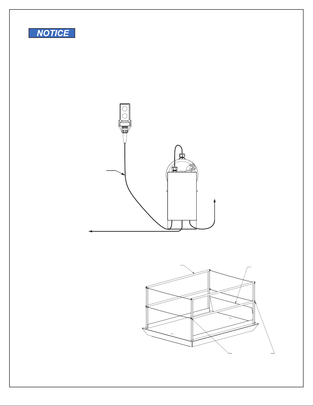
Typical required connections during installation shown here.
12.If applicable, install and anchor ramp.
13.Install handrails and snap
cables/ chains.
14.Check all hydraulic hoses
and connections, wiring and
electrical connections, and
other components for proper
installation and damage.
24/1/60 CONTROL SIGNAL &
G
ROUND FROM CONTROL PANEL
T
ERMINALS TO JUNCTION BOX IN
BASE FRAME. FOR LIMIT SWITCHES
AND
/OR OTHER DEVICES MOUNTED
O
N LIFT (IF APPLICABLE).
208/230/460 & GROUND
FROM SUPPLY TO
CONTROL PANEL
24/1/60 CONTROL
SIGNAL
& GROUND
FROM CONTROL
PA
NEL TERMINALS TO
CONTROLS
BEFORE PERSONNEL MAY
RIDE ON LIFT
MUST BE SECURED
ALL SNAP CHAINS/CABLES
THROW OVER PLATE
MUST BE IN RAISED
POSITION BEFORE
RAISING OR LOWERING
THE PLATFORM
ALL HANDRAILS MUST BE
INSTALLED AND SECURED
BEFORE PERSONNEL MAY
RIDE ON LIFT

16
Presto Lifts PDL Manual
4.7 Testing
Fall Risk. No personnel are to be on the platform unless the handrails
and snap cables are installed and secured.
The throw-over plates must be raised before raising or lowering the lift.
1. Verify all hydraulic and electrical connections are completed according to the schematics.
2. Verify all tools, debris, and personnel are clear of the lift.
3. Turn on the main electrical disconnect switch to power the hydraulic power unit (HPU).
4. Press and hold the up button on the operator controls. The HPU motor should start and the
lift should begin to raise.
5. Raise the lift until maintenance device(s) are not longer supporting the lift, then release the
button. The motor should turn o and the lift should come to a stop and hold its position.
6. Disengage and stow the maintenance device(s).
7. Press and hold the up button. Raise the lift to the fully raised position. Release the button
as the lift reaches the end-of-travel.
Do not continue to power the lift once the lift has reached the end-of-
travel or the lift may be damaged.
If the lift is equipped with a vertical travel limit switch, the motor should
automatically turn o as the lift reaches the fully raised position. If the
lift reaches the end-of-travel before the limit device turns o the motor,
or the motor turns o before reaching the fully raised position, see
section 6.3 Adjusting Vertical Travel Limit Devices.
8. Press and hold the down button on the operator controls. The down valve should energize
and the lift should begin to lower. The motor should not start.
9. Lower the lift approximately one foot then release the button. The lift should come to a stop
and hold its position.
10.Lower the lift to the fully lowered position.
11. Cycle 2-3 times. The lift should raise and lower smoothly.
Some bouncing may occur during the initial cycles due to air in the
hydraulic system. Continue to cycle the lift until the problem stops. If
the issue does not stop, see section 7. Troubleshooting and/or contact
Customer Service for assistance.
12.Ensure the throw-over plate(s) move freely.

17
Presto Lifts PDL Manual
5. Operation
Before operating this machine, read and understand this manual. Inspect the machine, electrical
and hydraulic components, controls and cords for excessive wear and/ or damage. If excessive
wear or damage is found, remove the machine from service and contact maintenance
personnel. Inspect all precautionary labeling. If any label is missing or illegible contact the
manufacturer for replacement labels. Ensure area is free of debris.
Before raising or lowering, raise throw over plate(s) and bridge plate(s)
to avoid damaging the plate(s).
For use with two wheel dollies, hand carts,and hand pallet trucks only.
To avoid death or serious injury:
• Only trained and/or qualied personnel shall operate this machine.
• Fall Risk. No personnel are to be on the platform unless the handrails and snap cables
are installed and secured.
• Loads that may shift during operating must be secured before operating.
• Keep hands, feet, and loose clothing away from moving parts.
• Do not enter beneath the platform until the load has been removed and the machine has
been secured against lowering with the maintenance device(s).
• Do not load or unload the machine while moving.
• The load’s center of mass must be centered on the platform. Uneven or o center
loading may cause excessive wear or permanent damage.
• During operation, operator must be in view of the machine at all times.
When not in use the platform is to be in the fully lowered position.
To raise the machine, press and
hold the UP button on the controls.
Release the button when the
platform is at the desired height.
To lower the machine, press
and hold the DOWN button on the
controls. Release the button when
the platform is at the desired height.
5.1 Loading
The Center of Gravity (CG) of all loads must be centered on the platform when lift is in motion.
Uneven loading can lead to excessive wear and premature failure. Any regular, uneven loading
must be oset by a counterweight installed on the opposite side of the platform. The combined
load must not exceed the rated capacity.
Do not load or unload the lift while moving.
Always secure loads that may roll or shift during operation.
BEFORE PERSONNEL MAY
RIDE ON LIFT
MUST BE SECURED
ALL SNAP CHAINS/CABLES
THROW OVER PLATE
MUST BE IN RAISED
POSITION BEFORE
RAISING OR LOWERING
THE PLATFORM
ALL HANDRAILS MUST BE
INSTALLED AND SECURED
BEFORE PERSONNEL MAY
RIDE ON LIFT

18
Presto Lifts PDL Manual
6. Maintenance & Repair
Only trained and/ or qualied personnel shall perform maintenance or
repair of this machine.
High Voltage: Electrical service and installation must be performed by
trained and/ or qualied personnel. Disconnect and lock out electrical
supply before performing any maintenance or repair.
Pressurized uids can penetrate skin and cause severe injury or
death. Always use proper personal protective equipment when
working with pressurized systems. Relieve hydraulic system pressure
before performing any maintenance on the hydraulic system. Contact
Customer Service for assistance.
Pinch points and Crush Hazards exist when moving and transporting
the machine. Do not enter under any equipment while moving or
transport. Keep hands, feet, and loose clothing away from moving
equipment.
Always use appropriate Personal Protective Equipment when
performing and maintenance or repair.
Do not adjust the hydraulic pressure relief valve. This valve is pre-set
and adjustment may cause the machine to fail.

19
Presto Lifts PDL Manual
6.1 Maintenance Devices
Do not enter under the platform unless secure using the supplied
maintenance devices.
The supplied maintenance devices are designed to support only the
unloaded lift. Failure to remove loads before engaging the maintenance
devices may result in failure of the maintenance devices or lift and
cause severe injury or death, and damage to the lift.
If the lift is equipped with a mechanical or proximity up limit switch that
prevents the lift from raising high enough to engage the maintenance
devices, the switch will need to be bypassed to engage the maintenance
device.
1. Ensure all debris, tools, and personnel are clear of the lift. Ensure load has been removed.
2. Raise the lift to the fully raised position.
3. Engage the maintenance device(s).
• Standing Style Maintenance Devices:
Remove the device from the
stowed position.
Install the maintenance device
over the post located on the
hinged end of the base frame.
The end of the device must be
resting on the base frame.
Standing style maintenance
devices must only be used
on the hinged end of the base
frame.
When engaged, the
maintenance device must be
resting on the underside of the
platform. Damage may occur
if the maintenance device
is resting on the structural
reinforcements.
If the lift is equipped with a
limit switch, the maintenance
device may be stowed on the
roller end of the base frame.
MAINT. DEVICE
STOWED
MAINT. DEVICE MAY BE
STOWED ON ROLLER END ON
LIFTS WITH LIMIT SWITCHES
MAINT. DEVICE
PLACED OVER
POST ON HINGED
END
MAINT. DEVICE
MUST BE USED ONLY
ON HINGED END
MUST REST ON MAINT. DEVICE
ON BASE FRAME
MAINT. DEVICE MUST REST
UNDERSIDE OF PLATFORM
MUST REST ON MAINT. DEVICE
ON BASE FRAME
MAINT. DEVICE MUST REST
UNDERSIDE OF PLATFORM

20
Presto Lifts PDL Manual
MAINT. DEVICES
STOWED (BOTH SIDES)
MAINT. DEVICES
ENGAGED
(BOTH SIDES)
MAINT. DEVICES
STOWED (BOTH SIDES)
MAINT. DEVICES
ENGAGED (BOTH SIDES)
MAINT. DEVICE AGAINST SIDE
AND FRONT OF BASE FRAME
• Flip-In Style Maintenance Devices:
Flip both maintenance devices into the roller tracks. Both maintenance devices must
be used.
• Drop-In Style Maintenance Devices:
Place both maintenance devices into the roller tracks. Place the devices such that the
long side is in contact with the side of the base frame and the end of the device is in
contact with the end of the base frame.
4. Lower the lift until the weight of the lift is supported by the maintenance devices. Continue
to hold the down button for ve seconds to relieve hydraulic system pressure.
This manual suits for next models
2
Table of contents
Other Presto Lifts Scissor Lift manuals


